
Abstract
Suitable electrothermal materials with high heating rates at low electric power are highly desirable for de-icing and thermal management applications. Herein, 3D epoxy resin/Ti3C2Tx MXene composites are synthesised and shown to be promising candidates for electrothermal heaters where the MXene serves as a nanoheater and the epoxy resin spreads the heat. A unidirectional freeze-casting technique was used to prepare an anisotropic Ti3C2Tx aerogel into which epoxy resin was then vacuum infiltrated and cured. The resulting composite showed an excellent Joule heating performance over repeated heating–cooling cycles. A steady-state temperature of 123 °C was obtained by applying a low voltage of 2 V with 5.1 A current, giving a total power output of 6.1 W cm−2. Such epoxy/MXene aerogel composites, prepared by a simple and cost-effective manner, offer a potential alternative to the traditional metal-based and nanocarbon-based electrothermal materials.
Export citation and abstract BibTeX RIS

Original content from this work may be used under the terms of the Creative Commons Attribution 4.0 license. Any further distribution of this work must maintain attribution to the author(s) and the title of the work, journal citation and DOI.
1. Introduction
Electric heating systems have been used over a century across a wide range of applications including local heating, automotive de-icing, drug release and micropatterning [1]. Electrothermal materials are used in this context to convert electrical energy into heat energy via Joule heating. Such materials must possess resistive behaviour, good thermal conductivity, high-temperature sensitivity, low energy consumption and good cycle stability [2, 3].
Traditionally, heavy metal alloys are used for Joule heating applications. These are very dense, costly, prone to oxidation and incompatible with polymer composites. Noble metals are also used for this purpose[4], but they fail to meet the growing demands in heating performance due to their high cost. Thus, carbon-based materials have received significant attention due to their attractive features such as energy-efficiency and excellent thermal/electrical/mechanical properties [5–9]. Unfortunately, these materials have a few shortcomings which lead to unsatisfactory performance when used for electrothermal applications. For instance, randomly oriented nanostructures fail to exhibit good mechanical properties, electrical stability and consume higher energy when used as a heating element [10]. Laser-induced reduced graphene oxide (rGO) can attain a temperature of 135 °C at a relatively high applied voltage of 9 V with 30 A current [11]. It has been seen that the steady-state temperature can be increased with applied voltage [12] which is not desirable and unsafe. In the case of rGO, oxygen-containing functional groups can be evaporated during the rapid local heating [12] which is detrimental in terms of structural stability and Joule heating performance over longer cycles.
With metal-like high conducting features (electrical conductivity ∼106 S m−1) and excellent thermal properties, MXenes, a family of 2D transition materials of metal carbide/nitride/carbonitride [13–16], may offer promising electrothermal properties [17, 18]. 3D porous macrostructures of MXenes offer outstanding performance, mostly in energy applications [19, 20]. It is also reported that simultaneous in-plane heat dissipation and cross-plane heat insulation can be obtained from MXene films [21]. Therefore, 3D MXene may be good candidate for elements in an electrothermal heater, however unwanted terminal groups, produced during the synthesis, are well-known to degrade the stability of MXenes and can have a negative impact on their Joule heating performance.
Epoxy resin exhibits low density and good compatibility with various substrates, finding application across wide ranging of applications, including aircraft, marine, automotive, and electronics due to its high mechanical strength [22]. However, its electrical insulating properties and deterioration at high temperatures are major shortcomings. Therefore, a recent trend is the drive towards the fabrication of epoxy-based composites to enhance the thermal and electrical properties, useful for Joule heating applications [23–26]. It has been reported that integrating aligned carbon nanotubes (CNTs) can result in an efficient heat transfer in polymer matrix composites [12]. Thus, designing a suitable composite to obtain a high electrothermal response, where aligned nanostructures may provide thermal transportation pathways and polymer matrix can dissipate the heat effectively at low driven voltage, is the focus of our present work.
In this regard, we have investigated the Joule heating characteristics of freeze-cast Ti3C2Tx MXene aerogels and their composites in combination with epoxy resin. The morphological, electrical and thermal properties of those materials are investigated. The Joule heating properties of the aerogels and their composites are measured in a custom-made set-up. Steady-state measurement of the surface temperature is performed to study reversibility and power–temperature characteristics. Finally, rapid and repeatable temperature cycling of the composites is demonstrated.
2. Experimental section
2.1. Materials
Ti3AlC2 powders (purchased from Laizhou Kai Kai Ceramic Materials Co., Ltd), lithium fluoride (LiF, purchased from Alfa Aesar), hydrochloric acid (HCl, purchased from Sigma-Alrdrich), epoxy resin (Araldite, LY5052) and the hardener (Aradur, HY5052 purchased from Huntsman) were used.
2.2. Preparation of Ti3C2Tx
Ti3C2Tx MXenes were prepared by in-situ HF etching of Ti3AlC2 powders and the experimental details can be found in our previous report [27]. Briefly, 3 M LiF were dissolved in 9 M HCl in a high-density polyethylene container at room temperature. Two grams of Ti3AlC2 powders were slowly added into the etching solution under vigorous stirring. The reaction was kept at 45 °C for 24 h to etch the Ti3AlC2. The etched MXenes were first washed with deionised water using centrifuge (at 10000 rpm for 5 min per cycle) for multiple cycles to remove the excess of acid. In between centrifuge cycles, vigorous shaking by hand was applied to delaminate the etched MXenes. The delaminated MXenes were collected by collecting the supernatants from multiple centrifuge cycles (at 3500 rpm for 5 min per cycle). The delaminated MXene suspension was concentrated via centrifuge (at 10000 for 1 h) to obtain a stock suspension which could later be used to prepare MXene suspensions for freeze-casting.
2.3. Preparation of 3D epoxy resin/Ti3C2TxMXene aerogel composites
The MXene solution prepared above (120 mg cm−3) was poured into a square PTFE mould (with dimension of 2 cm × 2 cm × 2 cm) and frozen by unidirectional freeze-casting over a copper substrate. Freeze-casting was conducted from 20 °C to −100 °C at a cooling rate of 10 °C min−1 and the solid structure then subsequently freeze-dried to obtain a Ti3C2Tx aerogel. To prepare the composite, hardener was added to epoxy resin (38 wt% with respect to the resin) and mixed by high shear mixing for 5 min. The mixture thereafter was kept in a vacuum oven for 10 min to remove any air bubbles. The Ti3C2Tx aerogel was immersed into the epoxy which was degassed and infiltrated by vacuum-assisted infiltration for 1 h (figure 1(a)). After an initial 24 h curing step at room temperature, the samples were then post-cured at 100 °C for 4 h in a conventional oven. The cured sample was polished to remove the excess epoxy resin that was not infiltrated into the aerogel to obtain the final epoxy resin/Ti3C2Tx MXene Aerogel composite. The mass loading of Ti3C2Tx in the epoxy resin/Ti3C2Tx MXene Aerogel composite was calculated by dividing the mass of the initial Ti3C2Tx aerogel by the mass of the final epoxy resin/Ti3C2Tx MXene Aerogel composite after polishing. The final epoxy resin/Ti3C2Tx MXene Aerogel composite was found to have 10 wt% loading of Ti3C2Tx . For comparison, Ti3C2Tx /epoxy composite with 10 wt% loading of Ti3C2Tx was prepared by dispersing delaminated Ti3C2Tx flakes in epoxy resin using a shear mixing method followed by the same degassing and curing process.
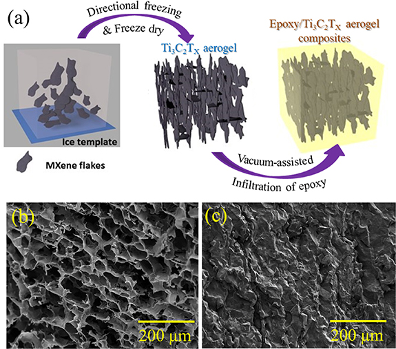
Figure 1. (a) Schematic of 3D epoxy resin/Ti3C2Tx MXene aerogel composite formation. Scanning electron micrographs of fracture surface of (b) bare Ti3C2Tx aerogel and (c) epoxy resin/Ti3C2Tx MXene aerogel composite.
Download figure:
Standard image High-resolution image2.4. Characterisation
The surface morphological images of the as-prepared samples were acquired by scanning electron microscope (Zeiss Ultra-55, Germany). X-ray micro computed tomography (µCT) imaging was performed using a Zeiss Versa 520, Oberkochen, Germany using a tube voltage of 60 kV and 5 W power in phase contrast mode. 3001 projections were taken at an exposure time of 12 s per projection. Source to sample and sample to detector distances were 26.0 and 43.5 mm respectively. A 4× magnification was used and voxel size was 1.264 µm. Data was reconstructed using x-ray microscopy (XRM) scout-and-scan control system (Zeiss, Oberkochen, Germany) and visualised using Avizo (version 2019.3; Thermo Fisher Scientific, Waltham, MA, US).
Powder x-ray diffraction (XRD) was undertaken using a Proto AXRD θ–2θ diffractometer (284 mm diameter circle) with a sample spinner and Dectris Mythen 1K (5.01° active length) 1D-detector in Bragg–Brentano geometry employing a Copper Line Focus x-ray tube with Ni Kβ absorber (0.02 mm; Kβ = 1.392250 Å) Kα radiation (Kα 1 = 1.540598 Å, Kα 2 = 1.544426 Å, Kα ratio 0.5, Kα av = 1.541874 Å) at 600 W (30 kV 20 mA). X-ray photoelectron spectra (XPS) measurements were performed by a PHI Quantera SXM/AES 650 Auger Electron Spectrometer (ULVAC-PHI, Inc.) equipped with a hemispherical electron analyzer and a scanning monochromated Al Kα (hυ = 1486.6 eV) X-ray source. To measure the impedance, the electrical contact on the samples was made with silver paint to reduce the contact resistance. All impedances were tested using a PSM 1735 Frequency Response Analyzer from Newtons4th Ltd connected with Impedance Analysis Interface with two terminals at the range of frequencies from 1 to 106 Hz. The specific conductivities (σ) of the materials were calculated from the measured impedances using the following formula:
where  is the complex admittance,
  is the complex impedance, t and A are the thickness and cross-sectional area of the sample, respectively.
2.5. Joule heating experiment
The Joule heating properties of all of the samples was conducted by applying the different voltages across the devices and measuring the current-induced temperature response. Samples were inserted with a custom-made clip and tightened enough to ensure a reliable and uniform electrical contact area. The electrical current and power applied to samples from two ends were controlled and monitored by the DC power supply. The maximum applied voltage was restricted up to 20 V and the maximum delivered current was restricted within 10 A for safety purposes. The surface temperature of each segment of the samples at steady-state condition was measured using an IR thermal camera with a recording function.
3. Result and discussion
3.1. Morphological analysis
The surface morphologies of Ti3C2Tx and its epoxy composite aerogels are shown in figures 1(b) and (c). An anisotropic porous nature of the Ti3C2Tx aerogel with interconnected MXene flakes is evidenced from figure 1(b). During the freeze-casting process, MXene flakes are pushed to the entrapped regions between the anisotropically grown ice crystals. As a result, highly ordered, layered assemblies of 3D porous MXene aerogel are formed having uniform pores with an average size of around 45 µm. Such a microstructure, where each flake can serve as an nanoheater [28], may facilitate better electrical and thermal transportation during the Joule heating process compared to their randomly oriented counterparts [29]. A jagged crack pattern and the rough surface of the epoxy/aerogel composite can be seen in figure 1(c), confirming the effective infiltration of epoxy into the MXene aerogel.
The µCT image of epoxy resin/Ti3C2Tx MXene aerogel composite is shown in figure 2. The virtual cross-sectional image (left) shows a homogenous MXene sheet domain structure across the scanned area. The 3D microstructure within a domain is shown for a region of interest on the right hand side of figure 2. A 3D lamellae structure of MXene is confirmed, which serves as a scaffold for the epoxy resin/Ti3C2Tx MXene aerogel composite. Within the µCT scanned volume, no air filled pores were visible which confirms the excellent infiltration of epoxy throughout the aerogel structure.
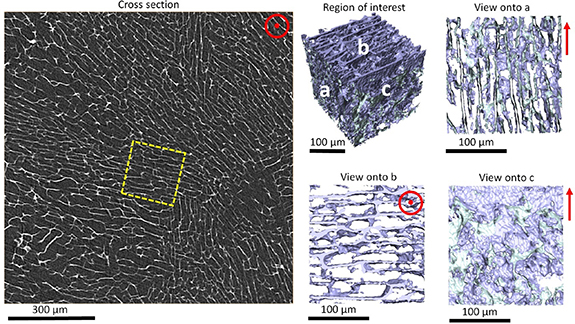
Figure 2. X-ray micro-CT of the epoxy resin/Ti3C2Tx MXene aerogel composite showing a virtual cross-sectional view (left) and a 3D segmented rendering with the epoxy rendered transparent for the region of interest (middle and right) showing sheets oriented within a single domain. Red vectors indicate the freezing direction. The yellow dashed box indicates the region of interest.
Download figure:
Standard image High-resolution image3.2. X-ray diffraction studies
To validate the successful synthesis of Ti3C2Tx , XRD of all the samples are shown in figure 3(a). The (002) peak of Ti3C2Tx is found to have shifted towards a smaller angle around 7° and broadened compared to its MAX phase counterpart (∼10°), which indicates a successful extraction of Al-atoms from Ti3AlC2. Moreover, the characteristic peaks between 33° and 43° of Ti3AlC2 have vanished for both of the Ti3C2Tx samples. These facts show that Ti3C2Tx was successfully synthesised by the in-situ etching process. It should be noted that the XRD spectra for delaminated Ti3C2Tx and as-prepared Ti3C2Tx aerogel are similar, indicating the excellent stability of Ti3C2Tx flakes even after freeze-casting.
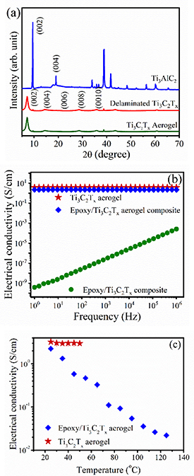
Figure 3. (a) XRD patterns of delaminated Ti3C2Tx and Ti3C2Tx aerogel with its MAX phase. Plot of electrical conductivity of epoxy resin/Ti3C2Tx aerogel composite and Ti3C2Tx aerogel with respect to the (b) frequency and (c) temperature.
Download figure:
Standard image High-resolution image3.3. Electrical conductivity
Increasing the resistive features of Ti3C2Tx by incorporating epoxy is evidenced in figure 3(b). The room temperature electrical conductivity for Ti3C2Tx aerogel/epoxy is found to be 2.1 S cm−1 at 1 Hz, which is lower than the bare Ti3C2Tx aerogel (3.1 S cm−1) and much higher than the epoxy resin (∼10−11 S cm−1). The relative reduction in electrical conductivity in the composite aerogel is due to the epoxy resin incorporated into the aerogel thereby separating the flakes slightly. It is noteworthy that response of both the Ti3C2Tx aerogel and epoxy resin/Ti3C2Tx MXene aerogel composite are quite independent of the applied frequency and hence the resistive component dominates in this case. The impedance of the comparison sample where Ti3C2Tx flakes were directly mixed into epoxy is also shown (figure 3(b)). This sample was highly resistive [28], showing the importance of the percolated, connected nature of the aerogel for imparting good electrical conductivity.
The electrical conductivity of the Ti3C2Tx aerogel was almost completely independent of temperature, whereas a drastic drop in conductivity occurred for the epoxy resin/Ti3C2Tx MXene aerogel composite (figure 3(c)). Note that the measurement of electrical conductivity of the Ti3C2Tx aerogel was restricted to 50 °C since MXenes are very sensitive to temperature under ambient conditions due to the attached functional groups. In contrast to the Ti3C2Tx aerogel, the electrical conductivity of epoxy resin/Ti3C2Tx MXene aerogel is measured at a relatively high temperature to ensure the stability and integrity of epoxy in the Ti3C2Tx aerogel.
3.4. Joule heating characteristics
The excellent Joule heating capability of the composite was validated by IR image inspection at different applied voltages (figures 4(a)–(c)). The steady-state temperature of epoxy resin/Ti3C2Tx aerogel composite was found to increase from 43 °C to 127 °C as the applied voltage was increased from 1 to 2 V. At 3 V applied voltage with 7.8 A current, the steady-state temperature of the composite was raised to 166 °C. The thermal IR images of the samples at 1.25, 1.75 and 3 V are shown in figure S1 (see supplementary materials (available online at stacks.iop.org/tdm/8/025022/mmedia)). The photographic images of bare MXene aerogel and epoxy resin/Ti3C2Tx aerogel composite before and after Joule heating are shown in figure S2 (see supplementary materials). The obtained result is impressive compared to the electrothermal materials reported in the literature (table 1). Our intention in table 1 is to show the importance of infiltrating the polymer into the 3D interconnected skeleton over the composite film such that best performance from the composite can be obtained. Essentially, 3D structures are well known to offer excellent electrical and thermal conducting pathways [26]. The steady-state temperature of Ti3C2Tx aerogel/epoxy is higher than the bare Ti3C2Tx aerogel at the same input voltage which can be visualised from figure 4. For instance, at the same input voltage of 2 V, the Ti3C2Tx aerogel surface can only heat up to 48.3 °C with 6.7 A current whereas the epoxy resin/Ti3C2Tx aerogel composite can provide a much higher steady-state temperature of 123 °C at 5.1 A current. Thermal IR images of the Ti3C2Tx aerogel at different voltages are shown in figures 4(d)–(f). The Ti3C2Tx MXene aerogel heater also outperforms the Ti3C2Tx MXene thin film and thread heater [17].
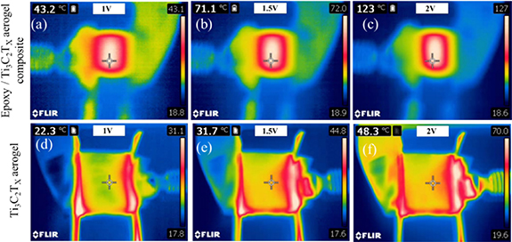
Figure 4. Steady-state thermal IR images of epoxy resin/Ti3C2Tx aerogel composite held at different input voltages of (a) 1 V, (b) 1.5 V and (c) 2 V; and Ti3C2Tx aerogel at different voltage of (d) 1 V, (e) 1.5 V and (f) 2 V.
Download figure:
Standard image High-resolution imageTable 1. Joule heating features of Ti3C2Tx aerogel and epoxy resin/Ti3C2Tx MXene aerogel with reported electrothermal materials (l: length, b: breadth and h: height; bold values represents this work).
| Materials (l cm × b cm × h cm) | Voltage applied (Volts) | Steady-state temperature (°C) | Response time (sec) | Heating rate (°C min−1) | Power density (W cm−2 and W cm−3) | Energy density (cm3 h−1) | Cycles |
|---|---|---|---|---|---|---|---|
| Ti3C2Tx aerogel (1.3 × 1.3 × 0.3) | 2 | 48.3 | 35 | 82.8 | 7.9 and 26.3 | 0.26 | 100 |
| Epoxy resin/Ti3C2Tx aerogel (1.3 × 1.3 × 0.3) | 2 | 123 | 140 | 52.7 | 6.1 and 20.3 | 0.79 | 100 |
| 3 | 166 | 160 | 62.3 | 13.9 and 46.3 | 2.06 | — | |
| MMT/Ti3C2Tx film (2 × 0.5) [21] | 3 | 60 | 120 | 30 | 0.6a | — | 10 |
| PPy/Ti3C2Tx textile (4 × 1) [30] | 3 | 57 | ∼90 | ∼38 | 0.07a | — | 50 |
| Laser-induced rGO (2 × 2 × 0.005) [11] | 9 | 135 | 10 | 810 | 0.389 | 0.22 | — |
| Au wire networks (0.13 × 0.13) [4] | 3 | ∼40 | ∼300 | ∼8 | 75a | — | — |
| rGO/epoxy film (0.5 × 2) [31] | 30 | 126 | ∼20 | ∼378 | 18a | — | 10 |
| Epoxy/GnP film (0.5 × 2) [25] | 20 | 40 | ∼20 | ∼120 | 0.08a | — | 10 |
| Epoxy/GNP/MWCNT film (0.5 × 2) [25] | 20 | 120 | ∼20 | ∼360 | 8 a | — | 10 |
| Epoxy/GNR composite (2.5 × 0.6 × 0.5) [24] | 40 | ∼170 | ∼500 | ∼20 | 53 | 14.7 | — |
| Graphene-coated glass rovings (10 × 10) [8] | 10 | 100.8 | 180 | ∼25.3 | — | — | — |
| GNP-coated carbon fibre veil/PDMS mats (20 × 20) [32] | 65 | 297.4 | 50 | 125 | 11.1 | — | — |
(MMT: montmorillonite, PPy: polypyrrole, GNP: graphene nanoplatelets, rGO: reduced graphene oxide, MWCNT: multi-walled carbon nanotube, GNR: graphene nanoribbon, PDMS: polydimethylsiloxane). a Values are calculated based on the data available in the respected references.
It should be noted that we did not observe any rise in temperature from the epoxy resin/Ti3C2Tx MXene composite made from simple shear mixing with any application of external voltage up to 20 V. This fact is due to the discontinuous MXene sheets in the composite which result in incomplete electrically and thermally conducting pathways. Although Ti3C2Tx has been found to be exhibit promising and impressive Joule heating features [17, 18], we demonstrate that the combination of epoxy and Ti3C2Tx aerogel can be a potential candidate due to better electrothermal behaviour.
Another prominent feature of the thermal images of all the samples is the spatial variation in temperature (over an approximate area of 1.3 × 1.3 cm2). It is noteworthy, that the central uniform part of the epoxy resin/Ti3C2Tx MXene aerogel composite is observed to be around 40% hotter than its peripheral region (figures 4(a)–(c)). On the contrary, a non-uniform temperature distribution over the surface has been observed from the Ti3C2Tx aerogel (figures 5(a)–(b)). In addition, the central part shows lower surface temperature than the two sides of the bare Ti3C2Tx aerogel. This is due to the porosity of the Ti3C2Tx aerogel which allows heat convection and radiation to the surrounding air and the thermally isolating nature of the air in the aerogel structure that restricts the heat transfer [33]. However at the sides of the sample, lower air density and direct contact with the clamp at the sides of the sample give rise to a locally higher temperature field (figures 4(d)–(f)). On the other hand, epoxy resin is uniformly incorporated throughout the Ti3C2Tx aerogel and hence able to maintain an uniform surface temperature upon application of the external voltage.
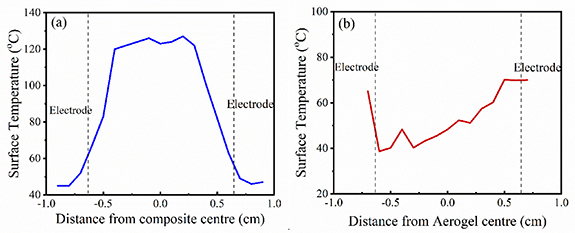
Figure 5. Temperature line profile on spatial variation of thermal image (a) epoxy resin/Ti3C2Tx MXene aerogel composite and (b) Ti3C2Tx MXene aerogel at an applied voltage of 2 V.
Download figure:
Standard image High-resolution imageAs seen from the figure 6(a), the Joule heating profile of the sample follows three stages: the initial increase in surface temperature with time (0–160 s), a steady-state zone (160–800 s) and a regime where it recovers to its original condition (800–1000 s). The rise in temperature is directly proportional to the square of the applied voltage and inversely proportional to the resistance of the materials. It has also been seen that the electrical conductivity reduces linearly with the temperature (figure 3(c)). Hence, at a higher applied voltage, a better and quicker response in the temperature distribution is observed for the epoxy resin/Ti3C2Tx aerogel composite (figures 6(b)–(c)). The response time, which is defined as the time required to attain 90% of the steady-state temperature from room temperature, is another deciding factor for evaluating the Joule heating performances (see table 1). The aerogel composite shows a heating rate of 3.5 °C s−1cm−3 in the initial stage under the applied voltage of 3 V (figure 6(c)). It is also important to see from figure 6(c) that the cooling profile of the aerogel composite follows similar trends with respect to the applied voltage as did the heating rate. A greater dissipation takes place at a higher temperature and it can maintain the steady-state temperature for the desired time, indicating its 'self-regulating' behaviour. As a higher voltage is applied, the power delivery is increased and hence the surface temperature of epoxy resin/Ti3C2Tx aerogel composite is increased up to 166 °C at 3 V. The drastic enhancement of specific power (power density) from 1.7 to 13.9 W cm−2 (5.7–46.3 W cm−3, considering a height of 3 mm) is observed as the input voltage increased from 1 to 3 V, as shown in figure 6(d). The energy densities of the studied materials are estimated using the relation: specific energy = specific power × heating time (see table 1). This result confirms the significant benefits of using our composite as an effective heater.
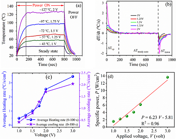
Figure 6. Plot of (a) temperature versus time and (b) rate of change of temperature versus time of the epoxy resin/Ti3C2Tx MXene aerogel composite at different applied voltages; (c) heating and cooling rate (solid line is guide to the eye only) and (d) specific power of composite with respect to the applied voltage.
Download figure:
Standard image High-resolution imageTo gain insight into the electric heating behaviour of the epoxy resin/Ti3C2Tx aerogel composite, the temperature–time profile (figure 6(a)) was further analysed. In the heating zone, the temperature–time profile can be expressed by the following equation [25, 34]
where T0, Tm, and Tt, are the initial temperature, maximum temperature and temperature at any arbitary time (t), respectively. The characteristic rate constant ( g) values for the composite could be evaluated by fitting data in the heating zone of the temperature–time plots, as summarised in table 2. A low
  g value represents a faster thermal response to the applied voltage. It is clearly seen from figure 6(a) that the surface temperature of the composite is higher and found to be stable over 10 min without any deterioration at higher input voltage (V0) and steady-state current (Ic). In this zone, the net heat gain is transferred to the surroundings by radiation and convection (hr+c) via the following equation
Table 2. Extracted characteristic parameters ( g,
g,  d, and hr+c) for the Joule heating performance of epoxy resin/Ti3C2Tx
aerogel composite at different applied voltages.
d, and hr+c) for the Joule heating performance of epoxy resin/Ti3C2Tx
aerogel composite at different applied voltages.
| Sample | Voltage (V) |
 g (s)
g (s) | hr+c (W °C−1) |
 d (s)
d (s) |
|---|---|---|---|---|
| 1 | 38.7  0.5 0.5 | 0.050 | 28.0  1.3 1.3 | |
| Epoxy resin/Ti3C2Tx | 1.25 | 64.5  1.0 1.0 | 0.035 | 86.8  6.5 6.5 |
| aerogel composite | 1.5 | 66.9  1.8 1.8 | 0.031 | 72.4  1.1 1.1 |
| 1.75 | 72.3  0.8 0.8 | 0.027 | 67.0  3.2 3.2 | |
| 2 | 44.0  2.6 2.6 | 0.027 | 55.0  4.0 4.0 | |
| Ti3C2Tx aerogel | 2 | 10.22  2.1 2.1 | 0.348 | 24.4  7.8 7.8 |
As given in table 2, this value of hr+c highlights the good electric heating efficiency of the epoxy resin/Ti3C2Tx
MXene aerogel composite [25]. In the cooling zone, the surface temperature of epoxy resin/Ti3C2Tx
MXene aerogel composite drops very rapidly as the input voltage is turned off. To find out the characteristic decay time constant ( ) the cooling profile was fitted with equation (4) and the extracted value is tabulated (see table 2).
A low  value at a higher applied voltage indicates faster recovery of the composite. Overall the aerogel composite shows a faster response with excellent heat dissipation along the plane of MXene alignment. Significantly, the cooling profile of the composite is found to be a mirror image of the heating characteristics being in good agreement with equations (2) and (4).
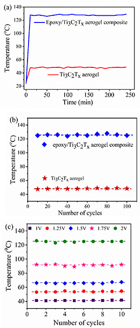
To examine the stability of the materials, the Joule heating test was repeated for a prolonged steady-state phase at 2 V applied voltage. Figure 7(a) shows the prolonged steady-state phase of bare MXene aerogel and epoxy resin/Ti3C2Tx MXene aerogel composite for 4 h. Moreover, figure 7(b) shows the Joule heating cycles of the epoxy resin/Ti3C2Tx MXene aerogel composite and bare MXene aerogel for several cycles at an applied voltage of 2 V. The temperature profile of bare MXene aerogel and epoxy resin/Ti3C2Tx MXene aerogel composite for repeated cycles is shown in figure S3 (see supplementary materials). The cycle stability of epoxy resin/Ti3C2Tx aerogel composite at different applied voltages is shown in figure 7(c) for each input voltage. The trapped water molecules between MXene layers could be evaporated during the rapid local heating, leading to crack formation and hence it may lead to a deterioration in performance. Since we cured the composite at the temperature of 100 °C over a long time of 4 h, such a possibility can be neglected here. Most importantly, the results shown in figure 7 offer direct proof of the structural stability of the aerogel composite as an electrothermal heater.
Figure 7. (a) Prolonged steady-state phase and (b) cycle test at applied voltage of 2 V of bare MXene aerogel and epoxy resin/Ti3C2Tx MXene aerogel composite; (c) cycle profile of temperature for the epoxy resin/Ti3C2Tx MXene aerogel composite at different applied voltages.
Download figure:
Standard image High-resolution image
To strengthen the statement, we carried out an XPS study of the studied materials before and after Joule heating (figures S4–S6 in supplementary materials). The extracted elemental composition is listed in table 3. As seen from table 3, epoxy resin/Ti3C2Tx MXene aerogel composite do not show any significant structural changes. However, slight changes in the Ti/C ratio from 1.29 to 1.53 have been observed for the bare Ti3C2Tx MXene after the Joule heating (table 3). This change can be attributed to the formation of TiO2 on the surface. It is important to note that, Ti/C ratio of epoxy resin/Ti3C2Tx MXene is relatively lower than the bare Ti3C2Tx MXene due to the carbon content of the epoxy. Although the epoxy resin/Ti3C2Tx MXene aerogel composite reaches a much higher surface temperature compared to the bare MXene aerogel, the existing epoxy resin can protect the MXene nanofillers in the composites from oxidation and hence the Ti/C ratio remains unchanged even after Joule heating. Thus, our result confirms that the both MXene aerogel and epoxy resin/Ti3C2Tx MXene aerogel composite have excellent structural stability even after several Joule heating cycles and after prolonged steady-state thermal exposure.
Table 3. The extracted parameters from XPS analysis of bare Ti3C2Tx MXene aerogel and epoxy resin/Ti3C2Tx MXene aerogel composite.
| Sample | Ti (at%) | C (at%) | Ti/C | O (at%) | F (at%) | Cl (at%) |
|---|---|---|---|---|---|---|
| Ti3C2Tx aerogel (before) | 47.80 | 37.00 | 1.29 | 8.80 | 2.80 | 3.60 |
| Ti3C2Tx aerogel (after) | 50.90 | 33.10 | 1.53 | 8.60 | 2.90 | 4.40 |
| Epoxy resin/Ti3C2Tx aerogel composite (before) | 25.60 | 55.60 | 0.46 | 14.70 | 2.17 | 1.97 |
| Epoxy resin/Ti3C2Tx aerogel composite (after) | 24.30 | 54.00 | 0.45 | 16.40 | 3.60 | 1.74 |
4. Conclusions
We demonstrate an efficient strategy for preparing an epoxy resin/Ti3C2Tx MXene aerogel composite via the infiltration of epoxy into the MXene aerogel. A high-efficiency energy conversion, rapid heating/cooling rate, and excellent stability for longer cycles are confirmed from the Joule heating tests for the epoxy resin/Ti3C2Tx MXene aerogel composite. Importantly, the fabricated aerogel composite has shown a more effective Joule heating response with three times higher steady-state temperature than bare MXene aerogel at the same applied voltage. The excellent Joule heating performance of the composite is attributed to the synergistic effect of MXene and epoxy resin along with their three-dimensional structure. The reinforced epoxy resin, on replacing the air from MXene aerogel, acts as an excellent mediator dissipating the heat along the direction of MXene sheet alignment and protects the MXene from oxidation. This novel approach to prepare 3D composites paves the way towards the fabrication of electrothermal heaters for use in energy-efficient de-icing and other thermal management applications.
Acknowledgments
T X acknowledges financial support from 2-DTech ltd, United Kingdom. S G, J W and S B acknowledge financial support from Heilongjiang Huasheng Graphite Co., People's Republic of China. I A K acknowledges Morgan Advanced Materials and RAEng for funding his Chair. S D R and P J W are grateful to the European Research Council for the funding given for Micro-CT imaging, under the European Commission's Horizon 2020 (FP8/2014-2020) ERC Grant Agreement Number 695638 (CORREL-CT). We thank the Henry Moseley x-ray Imaging Facility (HMXIF), which is supported through EPSRC Grant Nos. EP/M010619, EP/K004530, EP/F007906, EP/F001452, EP/I02249X, and EP/F028431. The HMXIF is part of the National Research Facility for Lab x-ray CT, which is supported through EPSRC grant EP/T02593X/1. The authors also thank Julia Behnsen for providing imaging expertise and support, Wenji Yang for help in experiments, Ben Spencer for XPS characterisation and Katie Lewthwaite for careful reading of the manuscript. We also highly appreciate and grateful to anonymous reviewers for their valuable and constructive suggestions.
Author contributions
P Y synthesised the MXene aerogel and epoxy resin/Ti3C2Tx MXene aerogel composite. P Y and T X conducted the general characterisation, electrical conductivity test and Joule heating characterisations. S G and J W synthesised the MXene. P Y, T X and S G drafted the manuscript and all authors interpreted the results. S D R and P J W conducted the µCT characterisation. I A K and S B supervised the research. All authors have given approval to the final version of the manuscript.
Conflict of interest
The authors do not have any competing financial interests.