
Abstract
We model and design a graphene-based infrared beamformer based on the concept of leaky-wave (fast traveling wave) antennas. The excitation of infrared surface plasmon polaritons (SPPs) over a 'one-atom-thick' graphene monolayer is typically associated with intrinsically 'slow light'. By modulating the graphene with elastic vibrations based on flexural waves, a dynamic diffraction grating can be formed on the graphene surface, converting propagating SPPs into fast surface waves, able to radiate directive infrared beams into the background medium. This scheme allows fast on–off switching of infrared emission and dynamic tuning of its radiation pattern, beam angle and frequency of operation, by simply varying the acoustic frequency that controls the effective grating period. We envision that this graphene beamformer may be integrated into reconfigurable transmitter/receiver modules, switches and detectors for THz and infrared wireless communication, sensing, imaging and actuation systems.
Export citation and abstract BibTeX RIS
Introduction
Graphene is an atomically-thin, two-dimensional (2D) carbon-based nanomaterial, which was first experimentally isolated in 2004 [1]. Since then, numerous efforts have been made to explore its exciting physical properties and applications in various fields of electronics, optics, mechanics, biology and chemistry [1–6]. Graphene's ultrahigh carrier mobility, stable thermal properties and carrier-density-dependent sheet conductivity [3], with a plasma frequency in the terahertz (THz) and infrared (IR) frequencies, make it an exciting platform for a variety of THz and infrared nano-photonic and nano-optoelectronic devices [4]. Graphene has been shown to support propagation of surface electromagnetic waves at its interface with a dielectric, so called 'graphene surface plasmon polaritons' (GSPPs). Over a high-quality graphene monolayer, GSPPs may have longer propagation lengths than surface plasmon polaritons (SPPs) on a metal surface [7] in the THz and infrared region. Additionally, their electromagnetic properties can be readily tuned through electronic and/or chemical doping, being able to dynamically control the plasma frequency of graphene. This intriguing optical response, combined with the need for tunable photonic/plasmonic devices that work over a broad frequency band, have fueled significant research efforts on graphene plasmonics. Recently, graphene has been proposed for compact and tunable metamaterials [7, 8], THz/infrared antennas [9–15], phase shifters [16, 17], plasmonic waveguides and interconnects [18], transformation-optics devices [19], cloaking devices [20–22], perfect absorbers [23–25], sensors [26, 27], modulators [16], couplers [28–30], filters [31] and photomixing frequency synthesizers [32]. The realization of these functionalities at the nanoscale may pave a practical way to wireless nano-communication and biomedical networks with carrier frequencies up to THz and even infrared frequencies [10, 33]. In these systems, deep-subwavelength graphene patches may serve as frequency-reconfigurable, electrically-small THz/infrared antennas connecting all the other mentioned nanodevices. By electrically gating the graphene micro/nano-patches, we may dynamically tune their operating frequencies. Moreover, by combining the THz antenna with novel graphene THz phase shifters [16], we may build reconfigurable transmitters/receivers that realize beamforming and beam steering functionalities illustrated in figure 1(a).
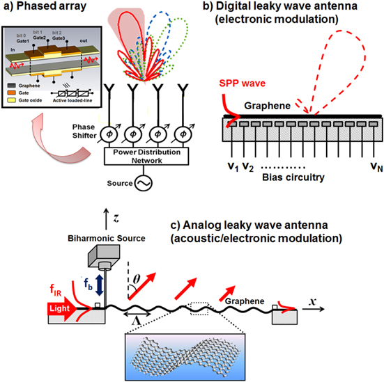
Figure 1. Schematics of a THz/infrared (a) phased array antenna based on graphene phase shifters, (b) graphene-based digital leaky-wave antenna for electronic beam scanning and (c) graphene-based analogue leak-wave antenna for acoustic-based beam scanning.
Download figure:
Standard image High-resolution imageIn this direction, recently a graphene-based THz leaky-wave antenna for electronic beamscanning was proposed [14], as schematically shown in figure 1(b). This THz antenna consists of a graphene monolayer with a high-density bias circuitry. Thanks to the gate-tuned conductivity of graphene, the use of multiple cascaded gates may electronically modulate the surface reactance by biasing each gate with a specific voltage. In the zero bias condition, the graphene monolayer provides a slow GSPP propagating wave. When the gate electrodes are properly biased, a 'digitized' sinusoidal modulation may be applied to the surface reactance of graphene, introducing high-order spatial harmonics that can support a 'fast-wave' leaky mode. By varying the modulation periods through different bias setups, the THz beam can be steered over a wide range of scan angles. However, in order to digitize the required sinusoidal surface reactance and reduce the radiation side-lobes, it is necessary to use a large number of gate electrodes underneath the graphene, which drastically increases the fabrication complexity and causes undesired phase errors due to electrostatic interference of the fringing fields. Besides, a high dc voltage is required to modulate the Fermi energy, and therefore the surface reactance of graphene. Since the variation of surface reactance is achieved in a digitized manner, we call the antenna in figure 1(b) a 'digital' graphene-based leaky-wave antenna.
It is well known that periodic corrugations on metallic surfaces can generate SPP resonances for various frequencies and angles of arrival (AOA) of the exciting electromagnetic field. Similar ideas apply to excitation of propagating GSPPs [28–30, 34, 35]. Based on the same concept, we propose in figure 1(c) an 'analogue' graphene-based leaky-wave antenna, which allows steering the infrared beam by exploiting flexural waves traveling on the graphene layer, which may produce the necessary continuous, sinusoidal diffraction grating on graphene, in order to turn slow-wave GSPPs into fast leaky-waves with desired angles of departure (AOD). A similar concept of 'light–sound interaction' was originally introduced in [28] to realize reconfigurable infrared couplers and absorbers.
Results and discussions
Figure 1(c) shows the conceptual and schematic design of a graphene-based analogue leaky-wave antenna. From [28], we know that a flexural wave traveling on a graphene sheet can be accurately modeled as a static grating with period  , which is an ideal condition to couple propagating and confined GSPPs into free-space radiation. Here we consider a suspended graphene monolayer with thickness δ = 0.3 nm, excited from one end by a mechanical actuator. Graphene's Young modulus E by far exceeds those of all natural materials, including steel [36, 37]. Combined with its extreme thinness, it is possible to model elastic vibrations of graphene in the transverse direction with the scalar biharmonic equation
  where W, q, βb
and D represent the vertical displacement field, source of vibrations (a concentrated point or line force), the flexural wave number and the flexural rigidity, respectively [38, 39]. The coefficient κ accounts for the stiffness of the substrate, and can be approximated as a Winkler foundation exerting an additional reaction force −κW on the thin plate [40]. The above biharmonic equation can be further simplified by defining a modified flexural wave number
where W, q, βb
and D represent the vertical displacement field, source of vibrations (a concentrated point or line force), the flexural wave number and the flexural rigidity, respectively [38, 39]. The coefficient κ accounts for the stiffness of the substrate, and can be approximated as a Winkler foundation exerting an additional reaction force −κW on the thin plate [40]. The above biharmonic equation can be further simplified by defining a modified flexural wave number  :
:  . Flexural waves that satisfy this biharmonic equation without source (i.e., q = 0) and the reaction force from the substrate (i.e., κ = 0) are the acoustic phonon modes supported by the graphene sheet, and their propagation constant satisfies the dispersion relation
  . Here
  is the angular vibration frequency, ρ is the density, and the flexural rigidity is given by D = Eδ3/[12(1 − ν2)], where ν is the Poisson coefficient [40, 41]. The flexural wave supported by the graphene sheet has a wavelength
  (figure 1(c)).
Figure 2(a) plots the normalized dispersion relation of flexural modes (Λb
versus the natural frequency ωb
/(2π) of the biharmonic wave) for a suspended graphene sheet (hollow circles) and a graphene sheet placed on a SiO2 substrate (solid circles); here we used realistic parameters δ = 0.3 nm, ρ = 2300 kg m−3, E = 1012 Pa, ν = 0.2 and D = 2.34 × 10⁻¹⁸ Pa m3 [36, 37]. From the dispersion relation in figure 2(a), it can be seen that  = 200 nm when the flexural wave frequency ωb
/(2π) is around
= 200 nm when the flexural wave frequency ωb
/(2π) is around  The periodicity is squeezed by reducing the frequency of excitation, and the smallest periodicity may be around 200 nm. Higher values of
  will result in the convergence of ωb
to
will result in the convergence of ωb
to  because of the presence of the Winkler foundation term κ/D, where
  [42].
[42].
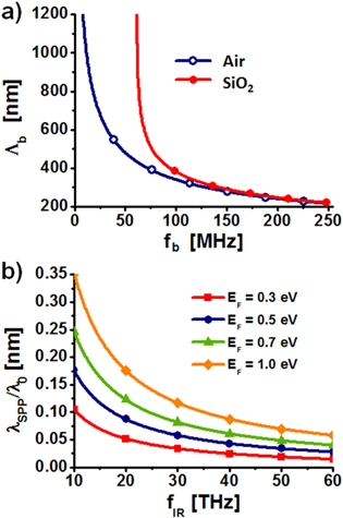
Figure 2. (a) Dispersion relation of the flexural mode for a suspended graphene monolayer and a graphene monolayer on a SiO2 substrate. The horizontal axis refers to the flexural wave frequency, while the vertical axis shows the square of the flexural wave number  with
with  ,
,  and
and  . (b) Dispersion relation of the GSPP for suspended graphene with different values of
  .
.
Download figure:
Standard image High-resolution imageNext, we investigate the propagation and leaky-wave properties of GSPPs on such flat or corrugated graphene sheets by modeling the flexural wave of graphene as a static grating with period  . Here we assume a sufficiently large graphene monolayer in the x–y plane, allowing us to ignore quantum effects and bandgap opening caused by limited lateral dimensions. It was shown [29] in this context that plasmons generated on structures with lateral dimensions larger than 100 nm may be treated using a classical approach (without opening the electrical bandgap), validating the following analysis. Below the interband transition threshold
  , generally valid for doped graphene at far-/mid-infrared, the complex intraband conductivity of graphene can be modeled as
![$[{{\Omega }^{-1}}]$](https://content.cld.iop.org/journals/2040-8986/16/9/094008/revision1/jopt496769ieqn21.gif) , [11, 43, 44] where the Drude weight of graphene
, [11, 43, 44] where the Drude weight of graphene 
 is the angular frequency of light,
  is the Fermi energy,
  is the intrinsic relaxation time and is assumed to follow the relation
  (which accounts for plasmon loss due to the acoustic phonon scattering),
  is the electronic charge,
  is the reduced Planck constant,
  is the Fermi velocity (
 is the speed of light) and
  is the dc mobility [45, 46]. To date, a dc mobility as high as
  has been measured in suspended graphene [45] and
  in chemical-vapor-deposited (CVD) graphene on evaporated copper films [46] and
  in CVD graphene on the silicon oxide substrate [47]. In THz and most infrared bands,
 ![${\rm Im}\left[ {{\sigma }_{{\rm intra}}} \right]\gt 0$](https://content.cld.iop.org/journals/2040-8986/16/9/094008/revision1/jopt496769ieqn35.gif) and graphene sustains the propagation of transverse magnetic plasmon modes that possess an extreme confinement. By matching the boundary condition at the interfaces between graphene and two (top and bottom) dielectrics, the GSPP dispersion relation can be derived:
and graphene sustains the propagation of transverse magnetic plasmon modes that possess an extreme confinement. By matching the boundary condition at the interfaces between graphene and two (top and bottom) dielectrics, the GSPP dispersion relation can be derived:
where  is the GSPP wave number,
  and
and  are the wave number and permittivity of the ith dielectric medium at the graphene interface, respectively. For suspended graphene with
  and
and  the propagation constant can be simplified as

where  and
and  are the wave number and permittivity of free space, respectively. From (2), it follows that
  , i.e.,
  , which is quite different from the dispersion of SPPs in bulk metals
  at low frequencies. Figure 2(b) compares the effective SPP wavelength
  normalized to free-space wavelength
  for a flat graphene monolayer with different Fermi energies. It is seen that
  is significantly shorter than
  at low Fermi energies, leading to tightly confined GSPPs propagating along the graphene surface. It follows that it is hard to couple GSPPs into free-space radiation, even for a relatively high Fermi energy of 1 eV. In the following, we will demonstrate that this limitation may be overcome by bending the graphene sheet periodically using flexural waves.
In order to convert a guided mode with wave number  into a leaky mode, the grating period
  generated by the bending flexural wave must satisfy the relation

Here,  is the beam angle, which is the direction of maximum radiation of the leaky mode (see figure 1(c)), and
  is the spatial harmonic index denoting the grating mode order. Since GSPP is a slow wave with
  spatial harmonics
  can exist only for negative values of N. It is common for leaky-wave antennas to excite the
  harmonic, which avoids undesired grating lobes in the backfire direction, yielding:
where  is the free-space impedance. Equation (4) shows that
  depends on several design parameters, including the modulation period
  tuned by the vibration frequency
  , the graphene Fermi energy
  and the frequency of the electromagnetic wave
  .
.
The conductivity of a corrugated graphene sheet can be well modeled as a spatially modulated conductivity with the same period. By comparing the GSPP excitation on flat graphene with modulated conductivity with that on corrugated graphene, an effective modulation depth for the conductivity of a flat graphene sheet can be obtained [53]. For a modulation height of 100 nm, the equivalent variation in conductivity is around 5%. A Floquet mode analysis of such a periodic problem yields both real and imaginary parts of the propagation constant of the leaky modes supported by the structure. Since the structure has periodicity equal to Λb, the effective conductivity of the graphene sheet may be written as

where we assumed that the flexural wave travels along the  direction, and therefore the effective conductivity has no variations in the y direction. σm
is the expansion coefficient depending on the nature of the flexural wave and the boundary conditions at the end of the graphene layer. The dispersion relation for the modes supported by such geometry can be represented in matrix form as
direction, and therefore the effective conductivity has no variations in the y direction. σm
is the expansion coefficient depending on the nature of the flexural wave and the boundary conditions at the end of the graphene layer. The dispersion relation for the modes supported by such geometry can be represented in matrix form as

In the above equation δmn is the Kronecker delta and kz (n) is the propagation constant in the direction normal to the graphene sheet, satisfying the following relation

By solving det(A) = 0, complex values of propagation constant may be obtained. In the following, we assume that the expansion coefficients σm have only three nonzero values, implying that the flexural wave supports only the first harmonics. This is justified by the small period of the effective corrugations introduced by the flexural wave modulation on graphene.
Figure 3(a) shows the dependence of the beam angle on the infrared frequency  for various elastic frequencies; here we assume a constant Fermi energy
  and a 100 nm height for the acoustic wave. It is interesting that the beam angle can be tuned from backfire
  , broadside
  , to endfire
  by continuously scanning the infrared frequency. We note that, within the endfire and backfire cutoffs, the results obtained from the approximate formula (4) quantitatively agree with the rigorous modal analysis in figures 3(a) and (c). Figure 3(b) shows the normalized attenuation constant of the modes. The attenuation increases in the frequency band where a leaky mode is supported, as expected due to the radiation loss in the structure. Maximum radiation is found at broadside, as usual in leaky-wave antennas, but it is interesting that the losses are dominated by graphene absorption, rather than by radiation. Our results confirm that the vibration frequency may shift the operating infrared frequency band quite dramatically. For instance, the operating frequency for broadside radiation may be changed from ∼27 THz to ∼33 THz, as the vibration frequency is adjusted from 23.6 MHz to 46.28 MHz. This implies that the beam angle can also be tuned by scanning the elastic frequency at a monochromatic infrared frequency. Figures 3(c), (d) show the dependence of the beam angle and absorption factor on the vibration frequency at the infrared frequency
  . It is seen that the leaky wave may be continuously steered from backfire to endfire by scanning the flexural frequency, following well the prediction of (4). In addition, the Fermi energy of graphene, which is electronically tunable (see figure 1(b)), may also tune the beam angle and the range of operating flexural frequency. This indicates the unique property of the proposed setup, for which the beam angle can be independently controlled by the scanning infrared frequency, flexural wave frequency and graphene Fermi energy. In other words, the beamforming and beam steering operation of this infrared leaky-wave antenna may be controlled by photonic modulation (scanning infrared frequency), acoustic modulation (scanning vibrating frequency) and electronic modulation (tuning Fermi energy), thus offering ultimate design flexibility. The attenuation constant as a function of vibration frequency is shown in figure 3(d). By increasing the Fermi energy level a reduction in the normalized attenuation constant is attained, which can be attributed to a larger GSPP wavelength. Again, the increase of attenuation constant in the x direction for leaky mode is observable.

Figure 3. (a) Beam angle  versus infrared frequency
  for a graphene leaky-wave antenna in figure 1(c), operated by frequency scanning. The operating frequency band is shifted by applying different elastic frequencies
  . (b) Attenuation constant for the modes corresponding to the beam angles shown in (a). (c) Beam angle versus elastic frequency at
  for the same graphene leaky-wave antenna operated by elastic beamscanning. The operating elastic frequency is shifted by varying the Fermi energy of graphene. (d) Attenuation constant of the same modes as in (c).
Download figure:
Standard image High-resolution imageFigure 4 shows the variation of infrared frequency with the elastic frequency for broadside operation; here both  (solid symbols) and
  (hollow symbols) spatial harmonics are presented. It is observed that the
  spatial harmonic has a much higher operating frequency compared to the dominant
  spatial harmonic. The infrared frequency of operation can be blue shifted by either increasing the frequency of flexural waves or by lowering the Fermi energy of graphene. This can be explained by the fact that
  is dramatically reduced by increasing
  , as shown in figure 2(a), which in turn raises the operating infrared frequency. Since
  can be tuned from a few
  to
to  this setup provides the unique modulation properties to couple GSPPs into leaky waves over a broad range of THz and infrared frequencies. We note that the large
  (which decreases with increasing Fermi energy) compared to the free-space wave number
 implies that the optimum
  is much smaller than the free-space wavelength. This deeply subwavelength
  in turn ensures complete absence of undesired grating lobes.

Figure 4. Operating infrared frequency versus elastic frequency for a graphene leaky-wave antenna with its radiation locked to broadside direction. Solid and hollow symbols refer to the  and
and  spatial harmonics. Here different Fermi energies are also shown for comparison.
Download figure:
Standard image High-resolution imageNext, we investigate the calculated radiation patterns of the vibrating graphene layers. In the case of periodic leaky-wave structures, the radiation pattern  can be well approximated by the array factor (AF) of an associated phased array [48–50], expressed as:

where  is the number of corrugations along the propagation axis (here we assume an infinitely long graphene sheet with
  ), I0 is the amplitude of the leaky mode and α and β are its attenuation and propagation constant respectively. Unlike a conventional phased array, as in figure 1(a), for which the phase factor of each element is controlled by phase shifters, here the leaky-wave antenna is fed continuously by the modified GSPP. The attenuation constant
  where
where ![${{\alpha }_{{\rm spp}}}={\rm Im}\left[ {{\beta }_{{\rm spp}}} \right]$](https://content.cld.iop.org/journals/2040-8986/16/9/094008/revision1/jopt496769ieqn94.gif) is due to the plasmon loss and
is due to the plasmon loss and  is due to the radiative energy leakage (leakage rate), has been calculated rigorously in figure 3. The total radiation efficiency of this antenna can be then calculated as [49]:

where ![${{L}_{{\rm g}}}=3/\left[ 2\left( {{\alpha }_{{\rm spp}}}+{{\alpha }_{{\rm rad}}} \right) \right]$](https://content.cld.iop.org/journals/2040-8986/16/9/094008/revision1/jopt496769ieqn96.gif) is the effective length of the antenna for 95% dissipated power [49]. For our design, we obtain
is the effective length of the antenna for 95% dissipated power [49]. For our design, we obtain  for a graphene leaky-wave antenna with
  and
and  , and 100 nm high acoustic excitation, which is consistent with the small effect of radiation loss on the overall damping factor of the graphene leaky-wave modes. The efficiency can be increased by increasing the amplitude of acoustic modulation. For example, by increasing the amplitude of modulation to 150 nm, which corresponds to a modulation depth of ∼9% in the conductivity, the efficiency will rise to 12%. We notice that the radiation efficiency, which relates antenna gain
  to its directivity
  , may be significantly improved by using high-quality graphene with high mobility up to
  . A low-loss graphene sheet can significantly increase the effective antenna aperture and, therefore, enhance radiation efficiency and gain, as discussed in the following.
Figure 5(a) shows the normalized radiation pattern for graphene leaky-wave antennas at  , steering the beam from
  to
to  ; (a)–(c) represent different graphene mobilities. The Fermi energy of graphene
  and the flexural wave frequency corresponding to different steering angles are consistent with figure 3. It is evident that the beam direction can be switched from backfire to endfire by tuning the frequency of flexural wave synthesizer. The results agree very well with (4). We note that the switching speed of the elastic device can be quite fast. As a result, the graphene leaky-wave antenna may be of interest for high-speed beamforming and beam steering devices operating in the THz and infrared spectrum. Figures 5(a)–(c) indicate that the antenna directivity (the ratio between maximum and average radiation intensity [49]) can be enhanced by increasing the graphene mobility, which reduces plasmon losses and effectively elongates the radiation aperture length. Figure 6(a) further studies the influence of traveling length of GSPPs on the antenna directivity. Here we assume different graphene sheet lengths L, with
  and
and  The infrared and flexural wave frequencies are respectively
  and
and  , which are tuned for radiation at 45°. It is observed that the antenna directivity increases when increasing the total length of the graphene layer (effective radiation aperture size), but the increase is not as dramatic for
  . Therefore, it is of importance to synthesize high-quality, moderately long graphene sheet in order to increase
  and enhance the gain of the graphene leaky-wave antenna. Another possible way to enhance the antenna gain is to increase the Fermi energy of graphene, which also effectively increases the relaxation time associated with plasmon losses. Figure 6(b) shows the radiation patterns for a graphene leaky-wave antenna with different Fermi energies; here the infrared frequency is fixed to
  , the radiation is locked to 45° direction, and the elastic frequencies are tuned for different Fermi energies to keep the radiation in the same direction. It is seen that the antenna directivity is enhanced by doping the graphene to a higher Fermi level. We expect quite a satisfactory antenna gain with high-carrier-mobility and heavily-doped graphene sheets.

Figure 5. Radiation patterns for a graphene leaky-wave antenna with operating frequency  , Fermi energy
  and dc mobility (a)
  , (b)
, (b)  , and (c)
  The acoustic frequency is tuned to achieve
  beamscanning.
Download figure:
Standard image High-resolution image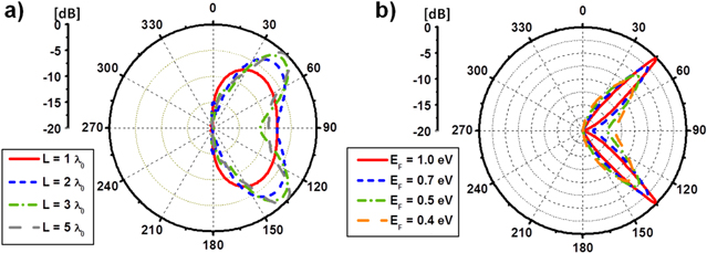
Figure 6. (a) Radiation patterns for a graphene leaky-wave antenna with operating frequency  with different lengths at Fermi energy
  and dc mobility
  . (b) Radiation pattern at the same frequency for a long antenna at different Fermi energy levels. Note that an increase in the Fermi energy level will result in an increase in the directivity of the antenna. For all cases, the radiation is locked to the 45° direction.
Download figure:
Standard image High-resolution imageFinally, we note that the beam steering concept introduced here can also be extended to 2D [51]. The pattern of surface perturbations can be designed by a 'holography' method, as typically considered at optical frequencies. Holography involves producing an interference pattern using two waves, and then using the interference pattern to scatter one wave to produce the other. The interference pattern formed by these two waves is recorded as a hologram. When the reference wave illuminates the hologram, it is scattered by the recorded interference pattern to produce a copy of the original object wave. For a reference wave  and an object wave
  , the interference pattern contains a term proportional to
  . When the interference pattern is illuminated by the reference wave, it renders
  , which forms a copy of the original object wave. For the case of a leaky-wave antenna, we may define the geometrical surface perturbation as the interference pattern between these two waves:
 ![${{Z}_{s}}\left( z \right)=j\left[ X+M\operatorname{Re}\left( {{\Psi }_{{\rm rad}}}\Psi _{{\rm surf}}^{*} \right) \right],$](https://content.cld.iop.org/journals/2040-8986/16/9/094008/revision1/jopt496769ieqn127.gif) where
where  and
and  are the average value and the modulation depth of the graphene corrugated structure in figure 1(c). Similar to the optical holography scenario, the radiated (object) wave results from the scattering of the SPP wave from the modulated surface, given by
  . For the previous 1D cases, the hologram is formed by the interference pattern of a 1D surface wave and a plane wave propagating
  degrees from the normal direction, and the result is the sinusoidal function shown in figure 1(c). The relationship between
  and the periodicity follows exactly the relationship in (4). Figure 7 shows an example of a 2D graphene leaky-wave antenna designed by the holography method. A monopole emitter at the center of a graphene sheet will excite outwardly propagating cylindrical surface waves. Assuming that we would like to have a pencil beam in a specific direction
  the interference between the fields associated with the surface wave (i.e.
  ) and the plane wave radiation pattern (i.e.
  ) on the graphene surface will define a hologram pattern. By applying a flexural wave point source at the center of the graphene sheet, the hologram can be formed to turn the cylindrical slow-surface-wave to directive radiation in the far-field. Figure 7 illustrates an example for broadside radiation. A 2D graphene leaky-wave antenna designed by the holography method will be discussed in more detail elsewhere.

Figure 7. A 2D graphene leaky-wave antenna designed to generate directive radiation in the broadside. Here, an infrared emitter is placed at the center of a graphene sheet and the hologram is generated by a flexural point-vibrating source. The hologram is determined by the interference pattern of a cylindrical surface wave (reference wave; here we assume  ) and a plane wave radiation (object wave).
Download figure:
Standard image High-resolution image
Conclusions
We have proposed an analogue graphene leaky-wave antenna that employs the grating structures generated by elastic vibrations of suspended graphene, coupling the slow-wave GSPPs into free-space radiation. We have theoretically demonstrated the possibility of achieving reconfigurable and steerable radiation patterns that could be dynamically switched by an acoustic frequency-modulation continuous-wave device. Moreover, our concept permits not only to control the leaky wave by geometrical properties (spatial harmonics related to the acoustic beamscanning), but also slow-wave GSPP properties that are tuned by the infrared frequency and the graphene's Fermi energy (frequency and electronic beamscanning). This antenna may enable fast switching of an infrared beam to various space channels, making a significant step towards the integration of multiple graphene plasmonic antennas for switching, spatial multiplexing, spatial shift keying and spatial division multiple access, as well as the emerging field of transformational plasmonics [52] and holography in the THz and infrared spectrum. We have also envisioned extension of these concepts to 2D leaky-wave antennas using holograms supported by flexural waves.
Acknowledgement
The authors would like to thank Dr Sebastien Guenneau for fruitful discussions on graphene acoustics. This work has been partially supported by the Welch Foundation with grant no. F-1662, the Army Research Office with grant no. W911NF-08-1-0348 and the Air Force Office of Scientific Research with grant no. FA9550-13-1-0204.