
Abstract
In vitro liver models allow the investigation of the cell behavior in disease conditions or in response to changes in the microenvironment. A major challenge in liver tissue engineering is to mimic the tissue-level complexity: besides the selection of suitable biomaterial(s) replacing the extracellular matrix (ECM) and cell sources, the three-dimensional (3D) microarchitecture defined by the fabrication method is a critical factor to achieve functional constructs. In this study, coaxial extrusion-based 3D bioprinting has been applied to develop a liver sinusoid-like model that consists of a core compartment containing pre-vascular structures and a shell compartment containing hepatocytes. The shell ink was composed of alginate and methylcellulose (algMC), dissolved in human fresh frozen plasma. The algMC blend conferred high printing fidelity and stability to the core–shell constructs and the plasma as biologically active component enhanced viability and supported cluster formation and biomarker expression of HepG2 embedded in the shell. For the core, a natural ECM-like ink based on angiogenesis-supporting collagen-fibrin (CF) matrices was developed; the addition of gelatin (G) enabled 3D printing in combination with the plasma-algMC shell ink. Human endothelial cells, laden in the CFG core ink together with human fibroblasts as supportive cells, formed a pre-vascular network in the core in the absence and presence of HepG2 in the shell. The cellular interactions occurring in the triple culture model enhanced the albumin secretion. In conclusion, core–shell bioprinting was shown to be a valuable tool to study cell–cell-interactions and to develop complex tissue-like models.
Export citation and abstract BibTeX RIS

Original content from this work may be used under the terms of the Creative Commons Attribution 4.0 license. Any further distribution of this work must maintain attribution to the author(s) and the title of the work, journal citation and DOI.
1. Introduction
Given all the vital functions of the liver in the body and its major role in maintaining homeostasis, liver failure is an important cause of mortality worldwide. The gold standard for clinical treatment is liver transplantation. However, the growing demand and the general shortage of donor organs as well as the risk of rejection and complications caused by lifelong immunosuppression require the development of alternative treatments. Liver tissue engineering focuses on the creation of artificial substitutes to aid in liver regeneration but is also of high interest for the fabrication of in vitro physiological or pathological models. Such in vitro liver models allow the investigation of cell–cell-interactions as well as of the cell behavior in disease conditions or in response to changes in the microenvironment and are therefore valuable tools for basic and clinical research, drug screenings or toxicological analyses [1].
Crucial requirements to consider in liver tissue engineering include the selection of a suitable biomaterial mimicking the extracellular matrix (ECM), the choice of cell sources and the definition of culture conditions. Beyond that, one of the most critical aspects influencing cellular responses is the application of an appropriate scaffolding method that defines the three-dimensional (3D) microarchitecture [2]. The liver is a highly complex organ composed of hepatic lobules as functional units. Each lobule consists of cords of hepatocytes which are organized in a hexagonal shape around the central vein, a sinusoid network in which the blood circulates from the peripheral portal vessels through the lobule to the central vein, and the bile ducts [3]. Thus, parenchymal cells (hepatocytes) and non-parenchymal cells (e.g. liver sinusoidal endothelial cells, stellate cells, cholangiocytes) are arranged in a highly organized structure. Mimicking the tissue-like patterning of cells and micro-environmental factors to achieve functional constructs in vitro is a major challenge, however, 3D bioprinting technologies expand the options of recreating the liver microarchitecture enormously.
3D bioprinting enables the fabrication of patterned cell-laden constructs by means of additive manufacturing using various bioinks which are printed according to a pre-defined design. There are many studies describing bioprinting of hepatocytes, most of them focused on the establishment of the printing approach and the development of suitable bioinks. Among the three main bioprinting technologies—laser/light-assisted, inkjet-based and extrusion-based—the latter has been predominantly investigated for the fabrication of 3D hepatic models and was used in the present work. In extrusion bioprinting, a highly viscous, shear-thinning hydrogel laden with cells, the bioink, is deposited strandwise and layer-by-layer to build up 3D constructs with defined architecture. After deposition, the constructs are stabilized by crosslinking of the hydrogel [4, 5].
The early work of Wang et al demonstrated that primary rat hepatocytes remained viable and functional for more than 2 months after extrusion-printing of cell-laden gelatin constructs which were crosslinked by 5 s incubation in glutaraldehyde [6]. In recent studies, alginate-based bioinks were investigated for hepatocyte bioprinting, as those have the advantage of printability with high shape fidelity and cell-compatible crosslinking by divalent ions [7–11]. To provide a more natural micro-environment, alginate-based inks have been blended with decellularized ECM [9] or Matrigel [11] whereby enhanced viability, proliferation and cluster formation of hepatocytes have been proven for Matrigel functionalization. Mazzocchi et al developed an extrudable, UV-crosslinkable ink based on the natural ECM molecules collagen type I and hyaluronic acid; Cuvellier et al investigated bioinks based on methacrylated gelatin [12, 13]. In all these studies, the embedded hepatocytes were functional, indicating the suitability of bioprinting approaches for the development of 3D liver models.
Bioprinting of co-cultures of hepatocytes with non-parenchymal cells has been realized in a few studies with bioinks simply containing a mixture of the different cell types, for example primary rat hepatocytes, human umbilical vein endothelial cells (HUVECs) and human fibroblasts suspended in a collagen-based ink that was printed into a stabilizing polycaprolactone framework [14]. This study demonstrated that the three cell types can be successfully co-cultivated and that the interaction of hepatocytes with non-parenchymal cells increased their survival and functionality within the bioprinted model. Two recent studies indicated the advantage of spheroid- and organoid-based bioprinting with respect to hepatic function that seems to be a result of the more physiological arrangement of the cells within aggregates [15, 16].
Patterned co-cultures of hepatocytes and non-parenchymal cells (fibroblasts, HUVEC and/or stellate cells), possessing a defined architecture, were generated by successive printing of different bioinks [13, 17–20]. By inclusion of sacrificial materials into the extrusion printing process, micro-channel structures have been integrated during fabrication of 3D liver tissue models, which are perfusable after removal of the sacrificial material and can be colonized with endothelial cells [21, 22]. Kang et al developed a two-step extrusion-bioprinting technique based on preset precursor cartridges and used it for the generation of hepatic lobule-mimicking structures with a patterned arrangement of hepatocytes and endothelial cells as well as a lumen in the center of the structure resembling the central vein: in the first step, the (bio)inks were filled in the different compartments of the precursor cartridge and in the second step, a heterogeneous, multi-cellular and multi-material strand was extruded. In this co-culture model, the functionality of the hepatocytes was increased compared to a simply mixed co-culture [23].
Patterned co-cultures can also be achieved by simultaneous extrusion of two different bioinks through coaxial nozzles, forming strands with a core and a shell compartment. Recently, we have applied core–shell bioprinting to establish a co-culture model of hepatocytes (human HepG2) encapsulated in the shell and fibroblasts (murine NIH 3T3) laden in the core [11]. Both, the core and the shell bioink were based on a blend of alginate and methylcellulose (algMC), whereby the alginate provides stability to the printed structures after Ca2+-induced crosslinking and the methylcellulose (MC) temporarily increases viscosity and shear-thinning, enabling 3D printing with high shape fidelity, and is released over time [24, 25]. For biological functionalization, the shell bioink was supplemented with Matrigel (algMC + Matrigel), to support survival and cluster formation of the hepatocytes, and the core bioink was either combined with fibrin or dissolved in human fresh frozen plasma (plasma-algMC). We observed that the expression of hepatic biomarkers such as albumin by the HepG2 clusters in the shell was enhanced when fibroblasts were co-cultivated in the core. The integration of fibrin or plasma in the core strongly induced cell spreading and interconnecting network formation of the fibroblasts which in turn stimulated the proliferation of hepatocytes into bigger clusters in the shell [11]. These observations indicated the high potential of core–shell bioprinting to control the behavior of hepatocytes by tailoring the 3D microenvironment and to study the crosstalk between the two cell types.
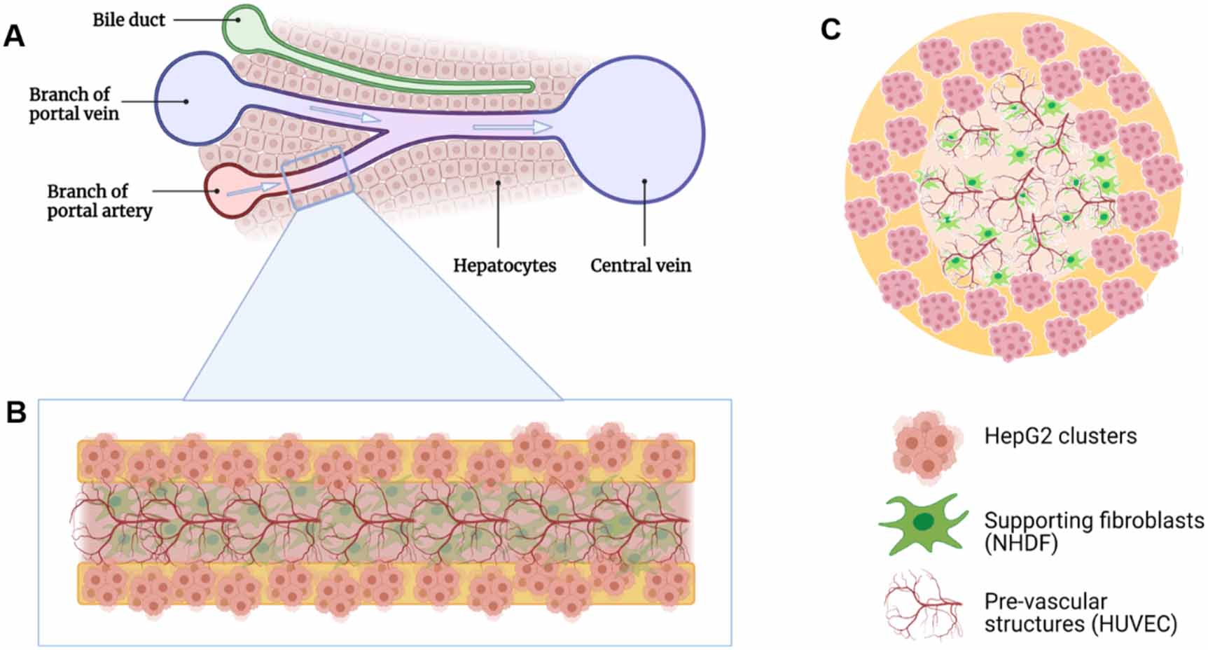
The aim of the present work was to develop a vascularized liver tissue model, based on core–shell bioprinting, which allows the study of cell–cell-interactions between hepatocyte clusters and vascular tube-forming endothelial cells and that can be further developed towards a functional liver sinusoid model. Thus, a triple culture model was established by combining three model cell lines of human origin: HepG2 were encapsulated in the shell, while HUVEC, together with normal human dermal fibroblasts (NHDFs) as supportive cells, were embedded in the core (figure 1). The shell compartment is based on algMC due to its excellent printing fidelity and stability; to support the hepatocytes, a biologically active component is required. The suitability of human blood plasma, which can potentially be used autologously, for this purpose was evaluated in comparison to Matrigel applied in our previous work [11]. For the core compartment, a natural ECM-like core ink was developed which is based on collagen-fibrin (CF) matrices, suitable to support angiogenesis, and allows 3D printing of stable core–shell vascularized constructs in combination with the shell ink. Finally, the cellular behavior and cell–cell interactions of the three cell types in the triple-culture model were characterized.
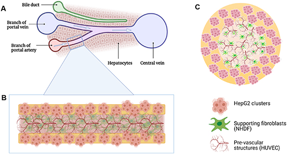
Figure 1. Schematic representation of the core–shell bioprinted triple culture liver model. (A) Liver sinusoid consisting of ducts and blood vessels that are surrounded by hepatocytes; (B) and (C) bioprinted strand with HepG2 clusters in the shell and HUVEC forming pre-vascular networks in the core; NHDF serve as supportive cells ((B): longitudinal and (C): cross section of the core–shell bioprinted strand). Images created using Biorender.com software.
Download figure:
Standard image High-resolution image2. Material and methods
2.1. Bioink preparation
2.1.1. Cells
Human hepatocellular carcinoma (HepG2) cell line was purchased from the German Collection of Microorganisms and Cell Cultures (DSMZ, Braunschweig, Germany); HUVECs and NHDFs were purchased from Promocell (Heidelberg, Germany). HepG2 and NHDF were expanded in cell culture medium consisting of Dulbecco's modified Eagle's medium (DMEM; Gibco, Life Technologies, Germany) with 10 vol% fetal calf serum (FCS; Corning, USA) and 100 U ml−1 penicillin and 100 μg ml−1 streptomycin (P/S; Biochrom, Germany) and HUVEC in endothelial cell growth medium (Promocell); all cells were cultured at 37 °C in a humidified 5% CO2 atmosphere. NHDF in passage 6–7 and HUVEC in passage 4 were used for the experiments.
2.1.2. Inks
The basic ink for the shell compartment consisted of a blend of 3 wt% alginate and 9 wt% methylcellulose (algMC) that was prepared as described previously [11, 24]. In brief, PRONOVATM UP LVM alginic acid sodium salt powder (Viscosity (mPa*s): 20–200, G/M ratio: ⩽1; Novamatrix, Norway) was dissolved at a concentration of 30 mg ml−1 in Hank´s Balanced Salt Solution (HBSS) by stirring overnight. After autoclaving of this solution (121 °C for 20 min), 90 mg ml−1 of autoclaved MC powder (molecular weight ≈ 88 000 Da, 4000 cP; Sigma Aldrich, USA) were added and the blend was left to swell for 2 h. Matrigel-supplemented ink (algMC + Matrigel) was prepared as previously described [11], by adding 5 vol/wt% Matrigel (Corning MatrigelTM membrane matrix; Fischer Scientific, Germany) to the swollen algMC blend immediately before adding the cells. Plasma-supplemented ink (plasma-algMC) was prepared as recently described [26]. Briefly, 30 mg ml−1 of autoclaved PRONOVATM UP LVM alginic acid sodium salt powder were dissolved in thawed plasma (Fresh frozen human blood plasma provided by the local blood bank (German Red Cross, Dresden, Germany)). After the addition of 9 wt% MC powder and tranexamic acid (0.7 mg per mg of fibrinogen; Amchafibrin, Rottapharm, Spain), the ink was allowed to swell for 2 h. Immediately prior to printing, HepG2 were added to the shell compartment inks in a concentration of 5 × 10⁶ cells per 1 g ink. Harvested cells were resuspended in co-culture medium (CCM) consisting of DMEM and endothelial cell basal medium (Promocell) mixed in a 1:1 ratio and supplemented with 15% heat-inactivated FCS (hi-FCS) and P/S, and then gently mixed into the inks with a spatula.
For the core compartment, an ink consisting of collagen (C), fibrin(ogen) (F) and gelatin (G) was developed. The CFG ink was prepared as follows: 120 mg ml−1 of UV-sterilized gelatin powder (gelatin from porcine skin; Sigma Aldrich, Germany) were dissolved in HBSS by stirring overnight at 40 °C to obtain a working concentration of 12 wt%. About 4 mg ml−1 of neutralized soluble rat tail-derived collagen type I (Meidrix, Esslingen, Germany), 15 mg ml−1 human fibrinogen (Tisseel Fibrin Sealant Kit; Baxter, USA) and 12 wt% gelatin were combined in equal parts to obtain final concentrations of 1.33 mg ml−1, 5 mg ml−1 and 4 wt%, respectively. The mixture was placed in a water bath at 37 °C for 20 min and then HUVEC and NHDF (2:3 ratio) were mixed in with a spatula in a concentration of 1.2 × 10⁶ total cells (resuspended in 100 μl CCM) per 1 g ink. The bioink was placed on ice with continuous gentle mixing for 2 min and then immediately used for printing.
2.2. Core–shell bioprinting, crosslinking and cultivation of the core–shell constructs
2.2.1. Core–shell bioprinting
The fabrication of core–shell constructs was based on the coaxial extrusion technique of 3D plotting [27]. A print head designed with two concentric needles was used in the pneumatic Bioscaffolder 3.1 from GeSiM (Radeberg, Germany) under sterile conditions. For the shell bioink (HepG2 in either algMC + Matrigel or in plasma-algMC), the outer needle with an outlet diameter of 800 μm was used while for the core bioink (HUVEC-NHDF in CFG), the inner needle with an outlet diameter of 400 μm was used. Both bioinks were dispensed simultaneously as a concentric strand using air as medium onto a six-well plate lid in a 0°/90° configuration in layer-by-layer fashion. The square shaped constructs (6 mm × 6 mm) consisted of two layers in a meandering pattern, composed of three parallel strands per layer. The printing parameters applied for fabrication of the core–shell constructs investigated in the different experiments are summarized in table 1.
Table 1. Summary of core and shell (bio)ink combinations and printing parameters applied in the experiments of this study.
| Core and shell (bio)inks | Printing pressure (kPa) | Printing speed (mm s−1) | |
|---|---|---|---|
| Shell compartment evaluation | Shell: Plasma-algMC + HepG2 | 65 | 3 |
| Core: CFG | 25 | ||
| Shell: AlgMC + Matrigel + HepG2 | 60 | 3 | |
| Core: CFG | 25 | ||
| Core compartment evaluation | Shell: Plasma-algMC | 70 | 3 |
| Core: CFG + HUVEC-NHDF | 20 | ||
| Shell: AlgMC | 80 | 3 | |
| Core: CFG + HUVEC-NHDF | 20 | ||
| Triple culture model | Shell: Plasma-algMC + HepG2 | 65 | 3 |
| Core: CFG + HUVEC-NHDF | 20 | ||
| Co-culture model | Shell: Plasma-algMC + HepG2 | 65 | 3 |
| Core: CFG + NHDF | 20 |
2.2.2. Crosslinking and cultivation
After printing, the constructs were stabilized by crosslinking in a 100 mM CaCl2 solution containing 0.3 U ml−1 thrombin (Tisseel Fibrin Sealant Kit) for 20 min. Thereafter, the constructs were transferred to 24-well cell culture plates containing CCM (DMEM and endothelial cell basal medium in 1:1 ratio, 15% hi-FCS, P/S) with or w/o 20 ng ml−1 recombinant human VEGF165 (Peprotech, Germany) as indicated for the respective experiments, and incubated at 37 °C in a humidified 5% CO2 atmosphere. In order to prove the feasibility of the CCM for the culture of HepG2, cultivation of core–shell-constructs with HepG2-laden shell was performed comparatively in CCM and the medium commonly used for HepG2 culture, consisting of DMEM, 10% FCS and P/S (supplementary figure S1).
2.3. Cell analyses
2.3.1. Microscopic analysis of cell viability and proliferation
Cell viability was assessed by simultaneous fluorescence staining of live and dead cells using Calcein AM/ethidium homodimer-1 (LIVE/DEAD Viability/Cytotoxicity Kit for mammalian cells; ThermoFisher Scientific, Germany) according to the manufacturer's instructions. After staining, z-stack images were acquired using confocal laser scanning microscopy (cLSM; Leica TCS SP5, Leica Microsystems, Wetzlar, Germany) in the Core Facility Cellular Imaging (CFCI; Faculty of Medicine, TU Dresden) and analyzed using the software Fiji (v 1.52p) [28].
Cell proliferation was assessed by the detection of newly formed cells using the Click-iTTM EdU imaging kit (Cell Proliferation Kit with Alexa FluorTM 488 dye; ThermoFisher Scientific). The constructs were incubated with EdU working solution for 8 h. After fixation and permeabilization, EdU was detected by the Click-iTTM reaction cocktail according to the manufacturer's instructions; DAPI was used for nuclear staining of both old and newly formed cells. Z-stack images were acquired using a cLSM (Leica TCS SP5) and analyzed using Fiji.
2.3.2. Microscopic analysis of cell morphology and functionality
Immunofluorescence staining was performed to observe specific biomarkers and morphological changes in the encapsulated cells. At given time points, constructs were collected, fixed with 4 vol% formaldehyde, permeabilized with 1 vol% Triton X-100 and blocked with 3 wt% bovine serum albumin (BSA), all diluted in HBSS. Primary antibodies were diluted in 0.5 wt% BSA, 0.2 vol% Triton X100/HBSS and secondary antibodies were diluted in 1 wt% BSA/HBSS. Different antibody combinations were used to detect specific biomarkers: rabbit Anti-Human Serum Albumin antibody (ab207327; Abcam, Germany; dilution 1:100) was detected with AlexaFluor 647-tagged goat anti-rabbit secondary antibody (ab150083; Abcam; dilution 1:200), rabbit Anti-Human CYP3A4 antibody (MA5-32718; ThermoFisher Scientific; dilution: 1:200) was detected with AlexaFluor 647-tagged goat anti-rabbit secondary antibody (ab150083; Abcam; dilution 1:200), and mouse Anti-Human CD31 antibody (M0823; Agilent Dako, USA; dilution 1:200) was detected with AlexaFluor 546-tagged goat anti-mouse secondary antibody (A-11030; ThermoFisher Scientific; dilution 1:200). Secondary antibodies were added together with Phalloidin iFluor 488 (ab176753; Abcam) and DAPI (ThermoFisher Scientific) to stain additionally cytoskeletal F-actin filaments and nuclei. Z-stack images were acquired using a cLSM (Leica TCS SP5) and analyzed using Fiji.
2.3.3. Biochemical analyses of HepG2 cell number development and albumin secretion
For biochemical cell number determination, triplicates of samples were collected at given time points, washed in HBSS and stored at −80 °C until analysis. For DNA quantification, the constructs were dissolved in 100 mM sodium citrate, and cells were lysed via incubation overnight at 60 °C and sonication on ice for 10 min. The QuantiFluorTM dsDNA system (Promega, USA) was used as to the manufacturer's instructions; the fluorescence signal was measured at wavelengths of 485/535 nm with a microplate reader (infinite M200pro; Tecan, Switzerland).
For quantification of metabolically active cells within the constructs, the enzyme activity of lactate dehydrogenase (LDH) was measured after cell lysis using the CytoTox96® Non-Radioactive Cytotoxicity Assay (Promega) as to the manufacturer's instructions. The samples were dissolved in 100 mM sodium citrate and incubated for 3 h at 37 °C. Lysis solution from the CytoTox96 kit was added to the dissolved constructs in a 1:10 ratio and the samples were incubated for 30 min at 37 °C, followed by sonication on ice for 10 min. After addition of the substrate solution, the absorbance was immediately measured at 490 nm for 5 min (kinetic measurement) using the infinite M200pro (Tecan).
Secreted albumin was quantified in the cell culture supernatant of constructs, collected at given time points, using a human albumin ELISA kit (Merck, Sigma Aldrich, Darmstadt, Germany) according to the manufacturer's instructions. Optical density was measured at 450 nm using the infinite M200pro (Tecan).
2.3.4. Gene expression analysis
Albumin gene expression was analyzed by quantitative real time polymerase chain reaction after reverse transcription (qRT-PCR) and ΔΔCT analysis; β-actin was used as reference gene. Constructs collected at given time points were dissolved in 100 mM sodium citrate at 4 °C and RNA was extracted using the Qiagen RNeasy Mini Kit (Qiagen, Germany). A minimum of 40 μg of extracted RNA were transcribed to cDNA using the SuperScriptTM II Reverse Transcriptase Kit (ThermoFisher Scientific) as to the manufacturer's instructions. The real time PCR was performed in the Applied Biosystems 7500 cycler (ThermoFisher Scientific) using 1 μl of cDNA as template, the TaqManTM Fast Advanced Master Mix as well as the TaqManTM gene expression kit for Human Albumin Serum (Hs00910225_m1, 137 bp) and β-actin (Hs01060665_g1; 63 bp) (all from ThermoFisher Scientific). The following amplification protocol was applied: initial pre-heating at 50 °C (2 min), activation at 95 °C (20 s), denaturation at 95 °C for 3 s and annealing at 60 °C for 30 s each cycle (40 cycles total). Fold change of expression was compared to non-encapsulated cells collected prior to printing.
2.4. Statistics
Statistical analyses were performed using two-way analysis of variance with Bonferroni correction. All analyses and graphs were generated in GraphPad Prism 9. Differences were considered as statistical significant if p < 0.05.
3. Results and discussion
3.1. Plasma supports proliferation and function of hepatocytes in the algMC-based shell compartment
In order to provide sufficient stability to the core–shell bioprinted vascularized construct, algMC was chosen as base ink for the HepG2-laden shell compartment. While algMC is cell-compatible, it does not actively support cell growth and should therefore be supplemented with a biologically active component. The suitability of human fresh frozen plasma as a biological component to support the formation of functional hepatocyte clusters was evaluated in comparison to Matrigel. Matrigel is a gelatinous ECM-like protein mixture derived from mouse tumor cells [29] and was used for biological functionalization of algMC in our previous study on hepatocyte bioprinting [11]. Fresh frozen plasma is a derivative of blood that contains besides the serum components fibrinogen and growth factors released from platelets during the preparation process; it has been shown to enhance viability, proliferation and differentiation of human pre-osteoblasts as well as mesenchymal stromal cells [26].
HepG2 were encapsulated either in plasma-algMC or in algMC + Matrigel and bioprinted as the shell compartment of core–shell constructs with a cell-free CFG core. The constructs were cultured for 14 d in CCM w/o VEGF, and hepatocyte viability, proliferation and functionality were evaluated.
3.1.1. Viability and proliferation
Representative images of viable and dead HepG2 cells in both bioinks are depicted in figure 2(A). Viable cells were observed in both biomaterials at day 1 of culture, with a visually higher viability noticed in plasma-algMC compared to algMC + Matrigel. This observation was supported by quantitative assays based on DNA content and LDH activity (figures 2(C) and (D)), confirming a better resistance to the stress during the fabrication process if the cells are embedded in the plasma-based ink. After 14 d of culture, cluster formation of viable cells was observed in both conditions, indicating that both bioinks supported cell proliferation albeit to a slightly different degree. Bigger clusters were visualized in plasma-algMC (figure 2(A)), suggesting higher proliferation. These observations were again reflected in quantitative analyses (figures 2(C) and (D)), with an increasing cell number over time. Cell proliferation was additionally visualized with EdU staining (figure 2(B)): tendentially more newly formed cells (nuclei depicted in green) were observed in plasma-algMC compared to algMC + Matrigel.
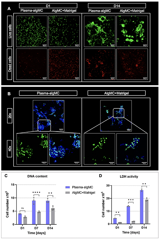
Figure 2. Viability and proliferation of HepG2 encapsulated in a plasma-algMC or algMC + Matrigel shell with a cell-free CFG core. (A) cLSM images of live (calcein-stained) and dead (ethidium homodimer-1-stained) cells in bioprinted constructs at day 1 and day 14 of culture; scale bars = 200 μm. (B) cLSM images of EdU stained cells in bioprinted constructs at day 14 of culture. Newly formed nuclei were stained with EdU (green), all nuclei with DAPI (blue); scale bars 20× = 100 μm, scale bars 40× = 50 μm. (C) DNA content-based and (D) LDH activity-based cell number quantification of bioprinted constructs at days 1, 7 and 14 of culture (Mean ± SD, n = 3, ns = non-significant, **p< 0.01, ***p < 0.001, ****p < 0.0001).
Download figure:
Standard image High-resolution imageThe higher cell viability and proliferation observed in plasma-algMC compared to algMC + Matrigel may be related to differences in the composition of plasma and Matrigel and/or the protein concentration in the respective bioinks. Human fresh frozen plasma is rich in proteins which provide the hydrogel with cell attachment sites, namely fibrinogen and fibronectin, and rich in growth factors and cytokines [26, 30]. Fibronectin is one of the main components of the hepatic tissue ECM [31, 32] and is known to be involved in hepatocyte differentiation and proliferation through the integrin-signaling pathway [33]. In contrast, the main components of Matrigel are laminin and collagen type IV [29], which are present in the hepatic ECM with a lower prevalence, constituting the basal lamina of the blood vessels and bile ducts [31]. The extracellular environment provided by the plasma-based hydrogel might therefore resemble the native hepatocyte microenvironment more closely. Furthermore, the presence of albumin in plasma [30] could also have contributed to the supportive effect of plasma as an increase in HepG2 proliferation in response to albumin was described recently [34]. Another contributing factor might be that the procedure used for preparation of the two inks was fundamentally different: for plasma-algMC, algMC were directly dissolved in fresh frozen plasma whose components are therefore homogenously distributed and present in high concentration. For the algMC + Matrigel on the other hand, algMC were dissolved in HBSS and active components via the Matrigel were only added at a concentration of 5% (v/v) to the swollen ink. Supplementation with higher concentrations of Matrigel was not possible as that reduced viscosity up to a point that the blend was not printable anymore.
3.1.2. Morphology and functionality
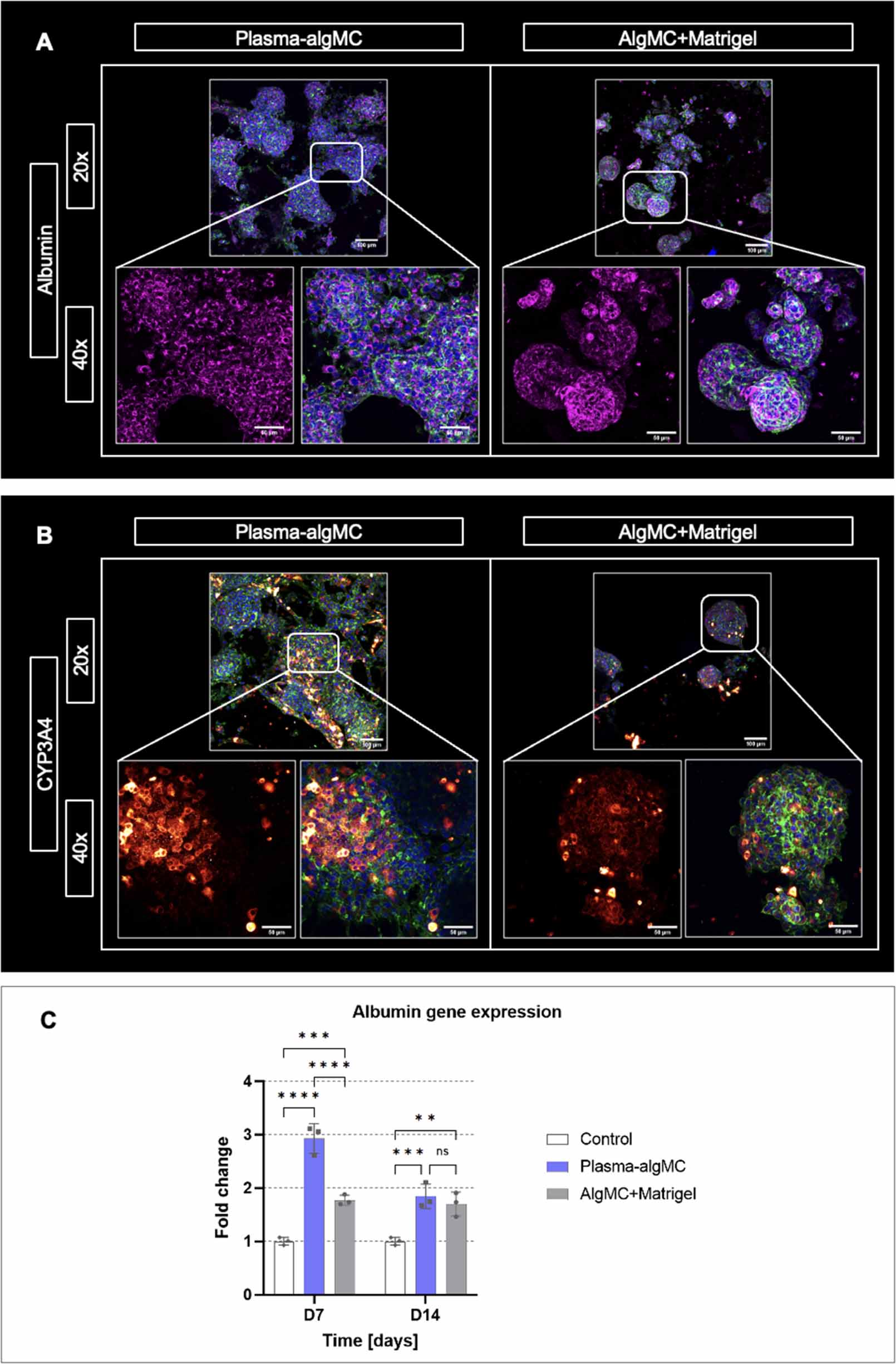
The morphology and organization of cellular aggregates as well as the expression of characteristic hepatocyte biomarkers were analyzed in both bioinks by immunostaining of embedded HepG2 for the biomarkers albumin and cytochrome P-450 (CYP3A4) as well as by albumin gene expression analysis. As illustrated by representative images in figures 3(A) and (B), HepG2 clusters were observed in both bioinks after 14 d of culture and appeared to have a larger size in the plasma-algMC bioink, demonstrating once again the enhanced proliferation achieved in comparison to the algMC + Matrigel bioink.
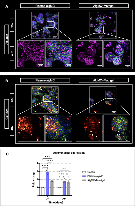
Figure 3. Morphology, organization, and biomarker expression of HepG2 encapsulated in a plasma-algMC or algMC + Matrigel shell with a cell-free CFG core. (A) cLSM images of cells stained for albumin (magenta), cytoskeletal F-actin (green) and nuclei (blue) at day 14 of culture; (B) cLSM images of cells stained for CYP3A4 (red/orange), cytoskeletal F-actin (green) and nuclei (blue) at day 14 of culture; scale bars 20× = 100 μm, scale bars 40× = 50 μm. (C) Quantitative RT-PCR analysis of albumin gene expression by HepG2 cells at days 7 and 14 of culture. Relative gene expression using β-actin as reference gene is shown; fold change relative to D0 (day of printing). Non-encapsulated cells collected at day 0 were used as control (mean ± SD, n = 3, ns = non-significant, **p< 0.01, ***p < 0.001, ****p < 0.0001).
Download figure:
Standard image High-resolution imageExpression of albumin was observed in both conditions without apparent difference (figure 3(A)). Albumin gene expression analysis indicated a significantly higher albumin expression in plasma-algMC compared to algMC + Matrigel on day 7, however, no significant differences were observed on day 14 of culture (figure 3(C)). Comparison of the bioinks with the 2D control (non-encapsulated HepG2) revealed that in both conditions, albumin expression was significantly higher than in the control at the selected time points, indicating that cell encapsulation in a 3D hydrogel, as well as an environment rich in proteins and growth factors, could support and promote hepatocyte functionality in terms of albumin expression. An enhanced expression of albumin and other hepatic biomarkers by HepG2 cells cultured in 3D Matrigel hydrogels in comparison to 2D culture has been previously reported [35]. Nishida and Taniguchi described an enhanced albumin expression by HepG2 induced by cell attachment sites of fibronectin [36] and therefore, the rich concentration of fibronectin in human blood plasma might have been contributed to the enhanced albumin expression observed in plasma-based constructs on day 7. The decrease in albumin expression observed on day 14 could be related to the large cluster size in plasma-algMC (figure 3(A))—larger aggregates have been associated with lower albumin production due to poor oxygenation in the center of the clusters [37].
CYP3A4 expression was detected in both conditions, with apparent higher intensity in the plasma-based constructs (figure 3(B)). Previous studies reported higher values of CYP3A4 activity and gene expression in Matrigel 3D systems compared to 2D culture [38]. Given that, to the best of our knowledge, there are no previous studies in which human blood plasma has been used as a biomaterial component for hepatocyte encapsulation, it is conceivable that the rich composition of the plasma-algMC bioink further increased the metabolic competence of HepG2 in comparison to the Matrigel-supplemented bioink. Nevertheless, further research is required to complement these observations.
3.2. Development of the CFG bioink supporting pre-vascular network formation in the core compartment
3.2.1. Conditions supporting pre-vascular network formation
Fibrin has been often used as supportive matrix in in vitro vascularization models because of its known support to the angiogenic process and critical role in cell-matrix interactions [39]. Hence, fibrin was chosen to be the main component for fabrication of the 3D environment for pre-vascular tube formation in the core compartment. Fibrin concentration is an important parameter that influences physicochemical characteristics of the formed gels and thus, regulates behavior of the encapsulated cells [40]. A preliminary experiment using an in vitro angiogenesis model, based on a co-culture of HUVEC and human mesenchymal stromal cells [41], was conducted to determine an optimal fibrin concentration: long tubular structures forming dense pre-vascular networks were observed in a concentration range of 5–7.5 mg ml−1, while lower or higher fibrin concentrations resulted in a reduced pre-vascular network formation (data not shown).
Another ECM biopolymer known to promote the essential processes for vasculogenesis is collagen type I [42]. It has been previously used in angiogenesis assays either alone or in combination with other biomaterials, such as Matrigel, and resulted in the formation of defined and lumenized pre-vascular networks [43]. Even though fibrin and collagen promote angiogenesis, they exhibit poor mechanical properties when used individually [44, 45]. As the combination of fibrin and collagen shows enhanced mechanical properties, probably related to the interpenetrating polymer network formed [46], it has been suggested for the development of vascular models [47]. For this work, a total protein content of 6 mg ml−1 (1 mg ml−1 collagen and 5 mg ml−1 fibrinogen), forming stable CF gels, was selected as base ink for the core compartment.
Besides matrix composition, an appropriate supportive cell type is important for endothelial cells to form stable pre-vascular networks. Fibroblasts have been widely used in angiogenesis models since they produce a supportive matrix [48] and have been shown to promote migration and proliferation of co-cultured HUVEC [49–51]. Fibroblasts have also been demonstrated to support hepatocytes, e.g. in the core–shell bioprinted NIH 3T3-HepG2 co-culture model previously established in our group [11]. For the envisaged triple culture model, NHDF were selected as supportive cells due to their human origin.
In an initial experiment, HUVEC and NHDF (ratio of 2:3) were encapsulated in CF gels; the bioink was extruded in 96-well plates and crosslinked with CaCl2 solution supplemented with thrombin. Ca2+ ions are necessary later to induce the gelation of alginate in the shell compartment of the core–shell triple culture model. Ca2+ ions are also known to support fibrin polymerization, initiated by thrombin, and enhance the stability of the formed networks [52, 53]. Before adding culture medium, the gels were incubated at 37 °C for 30 min to induce collagen polymerization, triggered by change to neutral pH and thermal gelation [47]. Thereafter, the gels were cultured in CCM with and without VEGF, given that this is an essential factor inducing angiogenesis [54, 55]. After 7 d, CD31-positive pre-vascular structures were formed by the HUVEC in the CF gels if the medium was supplemented with VEGF (figure 4), indicating that the 3D environment is suitable to support the formation of vessel-like networks and that external addition of VEGF is required in these conditions to induce it.
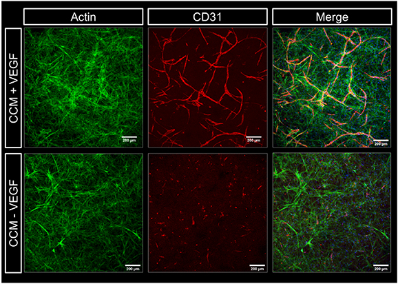
Figure 4. Influence of VEGF on pre-vascular tube formation of HUVEC co-cultured with NHDF in collagen-fibrin gels. Representative cLSM images of CF gels (1 mg ml−1: 5 mg ml−1) laden with HUVEC and NHDF (ratio of 2:3) at day 7 of culture in CCM with and without VEGF (20 ng ml−1). Cells were stained for cytoskeletal F-actin (green), nuclei (blue) and CD31 (red); scale bars = 200 μm.
Download figure:
Standard image High-resolution image3.2.2. Printable core ink
The low viscosity of the combination of fibrin and collagen before crosslinking remained an important limitation for extrusion-based 3D bioprinting. It is a common challenge in biofabrication to print structures from natural ECM biopolymers because of their low viscosity; hence, many studies suggest blending them with synthetic or more stable natural biomaterials as a strategy to enhance their rheological properties [56, 57]. The biocompatible cellulose derivative MC has previously been used as thickener to temporarily enhance the viscosity and shear thinning behavior of biopolymers (e.g. alginate, hyaluronic acid) and produce inks suitable for extrusion-based printing; MC is not crosslinked in the polymeric network and released over time during incubation [58]. The addition of MC powder (4 wt%) to the CF composite resulted in a very well printable ink, however, the extruded structures lacked a defined morphology and mechanical stability after crosslinking and disintegrated during incubation in medium. This is presumably related to MC interfering in the polymerization of collagen and fibrin networks, which resulted in an unstable matrix that would not support cellular function.
As alternative to temporarily enhance CF viscosity, gelatin was investigated. It forms physical bonds at temperatures below 37 °C (gelled state). This characteristic makes gelatin an optimal candidate as sacrificial stabilizer that supports the printability of low viscosity polymers and melts away during incubation under cell culture conditions [59–61]. An appropriate concentration of gelatin was necessary to ensure that the produced gel was viscous enough to be printed as core. On the other hand, a high concentration of gelatin could also interfere with the polymerization of collagen and fibrin networks. Finally, a concentration of 4 wt% gelatin in the CFG ink was found to sufficiently enhance the viscosity enabling printability as core and was selected for the subsequent experiments.
Concentrated (neutralized) collagen, fibrinogen and (melted) gelatin solutions were combined in a 1:1:1 ratio to obtain final concentrations of 1.33 mg ml−1 collagen, 5 mg ml−1 fibrinogen and 40 mg ml−1 gelatin. The mixture is incubated in a water bath at 37 °C for 20 min to induce collagen polymerization and after adding the cells, the mixture is placed on ice for 1–2 min to induce gelatin gelation. These steps allow for the resulting composite to be a sticky, partially gelled and therefore printable ink, as depicted in figure 5(A) with a transparent CFG core and a beige plasma-algMC shell. To visualize the CFG core, scaffolds with a plain algMC shell were printed (figures 5(B) and (C)) as the plasma results in an opaque appearance of the shell (figure 6(D)). Polymerized fibrin networks were visible in the core as white strands surrounded by the transparent algMC shell throughout the entire time of observation, indicating stability of the core–shell scaffolds over at least 10 d. Rheological analysis of the CFG ink at room temperature indicated shear thinning behavior (figure 5(D)) which is a requirement for its extrudability. The CFG ink extruded as monophasic strand did not result in stable structures after crosslinking; thus, stabilization provided by the shell is needed.
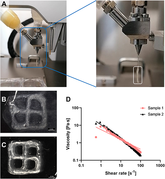
Figure 5. Printability and stability of the developed CFG ink used as core biomaterial in core–shell printing. (A) Coaxial extrusion (bio)printing module extruding CFG as core and plasma-algMC as shell. The white rectangle in the close-up image shows the core–shell strand being extruded below a thinner core(-only) strand, indicating that the viscosity of the CFG ink was sufficient to be extruded. (B) and (C) Representative images of a cell-free core–shell scaffold (algMC shell and CFG core) immediately after printing and dual crosslinking with Ca2+/thrombin (B) and after 10 d of storage in CCM (C). White crosslinked fibrin fibers are observed in the core compartment of the scaffolds surrounded by the transparent algMC shell; scale bars = 2 mm. (D) Rheological characterization of the CFG ink illustrating the shear thinning behavior of two representative samples at room temperature.
Download figure:
Standard image High-resolution image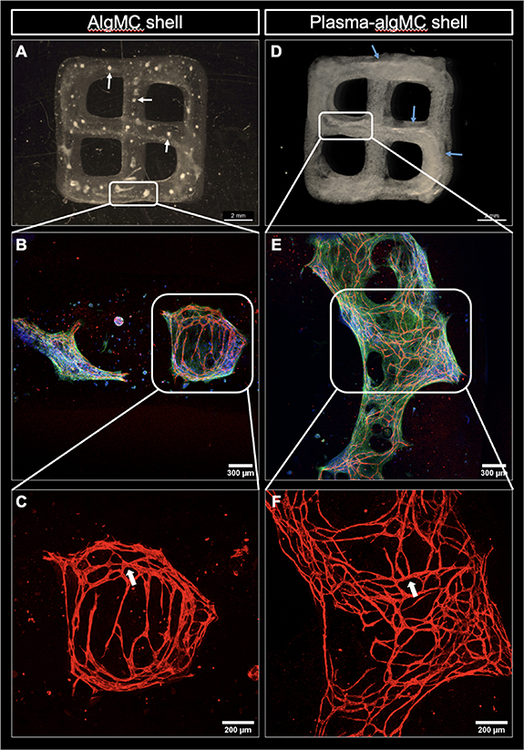
Figure 6. Core–shell constructs consisting of a HUVEC-NHDF-laden CFG core and a cell-free algMC or plasma-algMC shell. The constructs were imaged after 10 d of culture in CCM + VEGF. (A) Representative image of a core–shell construct with cell-laden CFG core and cell-free algMC shell; white arrows point to the disrupted CFG core through the construct. (B) Representative cLSM image showing pre-vascular structures formed within the CFG core surrounded by algMC shell and (C) higher magnification of CD31-positive pre-vascular structures; lumen formation is pointed by white arrows. (D) Representative image of a core–shell construct with cell-laden CFG core and cell-free plasma-algMC shell; blue arrows point to the continuous CFG core through the construct. (E) Representative cLSM image showing pre-vascular structures formed within the CFG core surrounded by plasma-algMC shell and (F) higher magnification of CD31-positive pre-vascular structures; lumen formation is pointed by white arrows. Images (A) and (D) were obtained with a stereomicroscope, scale bars = 2 mm. Images (B) and (E) were obtained with cLSM and show cells stained for CD31 (red), cytoskeletal F-actin (green) and nuclei (blue), scale bars = 300 μm; higher magnification in images (E) and (F): scale bars = 200 μm.
Download figure:
Standard image High-resolution image3.2.3. Pre-vascular network formation in the core compartment
Having shown printability and stability (figure 5) as well as the excellent cytocompatibility of the CFG core (supplementary figure S2), the next experiment aimed to investigate the formation of pre-vascular structures within the CFG core and to evaluate the impact of the plasma in the shell on the core compartment. HUVEC and NHDF in a ratio of 2:3 were encapsulated into CFG and extruded coaxially with either a pure algMC or a plasma-algMC shell. After dual crosslinking (Ca2+/thrombin), the constructs were cultured for 10 d in CCM with VEGF. A very interesting observation was that the presence of plasma in the shell ensured the integrity of the cell-laden core: while it was disrupted when printed within an algMC shell (figure 6(A); white arrows indicate the small pieces of CFG distributed along the construct), the core remained as a continuous strand even after 10 d of culture when surrounded by a plasma-algMC shell (figure 6(D); the blue arrows indicate the intact core). CD31-positive pre-vascular structures were formed under both conditions, indicating that CFG supports vascularization (figures 6(B) and (E)) and the formation of lumenized tubes (white arrows in figures 6(C) and (F)). However, these structures were more defined and denser in constructs with a plasma-algMC shell, suggesting that the rich composition of human blood plasma may further support the formation of pre-vascular structures. Fresh frozen plasma has been shown to contain angiogenic factors [26], which could promote the HUVEC tube formation in the core.
The stabilizing effect of the plasma-algMC shell might be explained by the presence of fibrinogen not only in the core—as part of the CFG ink, but also in the shell—as major component of plasma; the fibrinogen content of fresh frozen plasma was determined to be 2.26 mg ml−1 in a previous study in our lab [26]. During crosslinking induced by thrombin and CaCl2, the fibrinogen in both the core and shell compartment appeared to form fibrin networks within each compartment which were visible as thick fibrous strand in the core and as fine networks in the shell (figure 6(D)). The presence of fibrin in the core and shell may result in the interaction of both compartments through the formation of a fibrin network across the interface during polymerization and this might have prevented shrinkage and disintegration of the core. Such network may also facilitate the interaction between cells encapsulated in the core and shell compartments.
Since the fresh frozen plasma naturally contains proangiogenic factors [26], we investigated whether those, as components of the plasma-algMC shell, are sufficient to induce the formation of pre-vascular structures without additional VEGF supplementation of the medium. Therefore, core–shell constructs with a HUVEC-NHDF-laden CFG core and a cell-free plasma-algMC shell were cultured in CCM with and without VEGF. CD31-positive pre-vascular structures, which appeared to be lumenized (shown by the white arrows), were observed with and without VEGF supplementation. However, the networks formed in the absence of VEGF were far less dense, defined and branched as the ones formed in the presence of VEGF (figure 7). These observations indicated that the supply of angiogenic factors from the plasma-containing shell can induce the formation of pre-vascular networks in the core albeit with a lower efficiency than VEGF added to the medium. However, in contrast to the CF gels in which no vessels were detected in the absence of VEGF (figure 4), the CFG core compartment contained additionally gelatin which could also have contributed to the angiogenesis-stimulating effect. It was noticeable that the fibroblast network appeared significantly denser in the CFG core compartment (figure 7) than in the CF gel (figure 4). This might have been a result of the presence of gelatin, possibly by influencing the CF network formation, and/or of stimulating factors released from the plasma-containing shell. The latter can be assumed since a stimulating effect of plasma on proliferation and interconnecting network formation of fibroblasts has been observed in our previous study [11]. Therefore, the apparently stimulating effect of plasma-components in the shell on pre-vascular tube formation in the core could also be an indirect effect via an enhanced efficacy of the supportive fibroblasts.
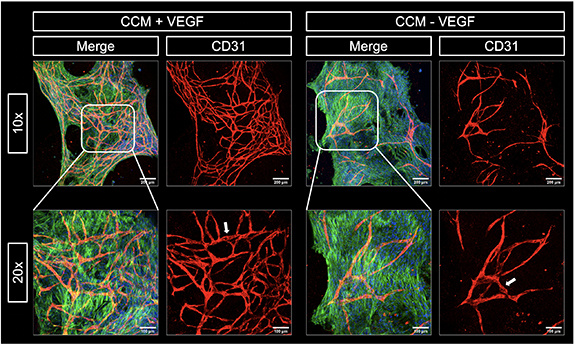
Figure 7. Influence of external VEGF on pre-vascular tube formation of HUVEC co-cultured with NHDF in CFG core with a cell-free plasma-algMC shell. Representative cLSM images of the cell-laden core after 12 d of culture of core–shell constructs in CCM with and without VEGF (20 mg ml−1). Cells stained for cytoskeletal F-actin (green), nuclei (blue) and CD31 (red). Lumen formation is indicated by white arrows. Scale bars 10× = 200 μm, scale bars 20× = 100 μm.
Download figure:
Standard image High-resolution image3.3. Core–shell bioprinted triple-culture model
3.3.1. Hepatocytes and endothelial cells express their phenotype in the triple culture model
After independent analysis of the cell behavior in either the core or the shell compartment in order to evaluate the impact of the ink compositions, a triple culture model was assembled by bioprinting of core–shell constructs with HepG2 encapsulated in the plasma-algMC shell and HUVEC-NHDF encapsulated in the CFG core. As the pre-vascular network formation was more efficient if the medium was supplemented with VEGF (figure 7), these triple culture constructs were cultured in CCM with VEGF. The presence of VEGF was proven to have no impact on HepG2 cells viability, proliferation (supplementary figure S3) or function (supplementary figure S4). In an initial experiment, immunostaining of biological markers revealed the formation of CD31-positive pre-vascular structures formed by HUVEC in the core and albumin expressing HepG2 cellular aggregates in the shell after 12 d of cultivation (figure 8). The core and shell were imaged independently, given that the structures were in different focal planes. Both sets of z-stacks were overlayed and are shown as a merge core–shell image, which depicts how hepatocyte clusters could interact with the cellular structures in the core at the interface of both compartments. A zone of potential interaction between HepG2 and NHDF is highlighted by white arrows, indicating the close proximity between the different cell types in the model. The formation of pre-vascular networks by HUVEC and the expression of albumin by HepG2 indicate that cell functionality was preserved when all components were put together into the triple-culture model.
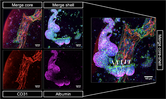
Figure 8. 3D core–shell bioprinted triple culture model. Representative cLSM images of the bioprinted triple culture construct, consisting of a HUVEC-NHDF-laden CFG core and a HepG2-laden plasma-algMC shell, at day 12 of culture in CCM with VEGF showing CD31-positive pre-vascular structures in the core (red) and albumin expressing HepG2 clusters in the shell (magenta). Merged images additionally show cytoskeletal F-actin (green) and nuclei (blue). The merge core–shell image illustrates the arrangement of the HepG2 aggregates around the pre-vascular network in the core (the latter indicated by white dashed lines). A zone of potential interaction between HepG2 and NHDF is depicted with white arrows. Scale bars = 100 μm.
Download figure:
Standard image High-resolution image3.3.2. Competition of HepG2 and HUVEC for supportive fibroblasts
To further explore cell–cell interactions in the model, the effect of HepG2 in the shell on the ability of HUVEC to form pre-vascular structures in the core was evaluated. HUVEC and NHDF were encapsulated in a CFG core and bioprinted with a plasma-algMC shell which was either cell-free or laden with HepG2. This experiment was a repetition of the experiment shown in figure 8 but included a HepG2-free control. As shown in figure 9(A), defined and dense CD31-positive tubular networks were formed by HUVEC when no HepG2 were present in the shell compartment, confirming the observation of the previous experiments (figures 6 and 7). However, when HepG2 were present in the shell compartment, HUVEC were not able to form pre-vascular networks in the core and appeared as CD31-positive single cells—in contrast to the previous experiment in which the same protocol was applied (figure 8). This finding indicates that a certain variability within the components of this highly complex system can have a strong effect on the cell behavior. In comparison to the previous experiment (figure 8), different batches of HUVEC and HepG2, with the same passage number and cultured under the same conditions, were used.
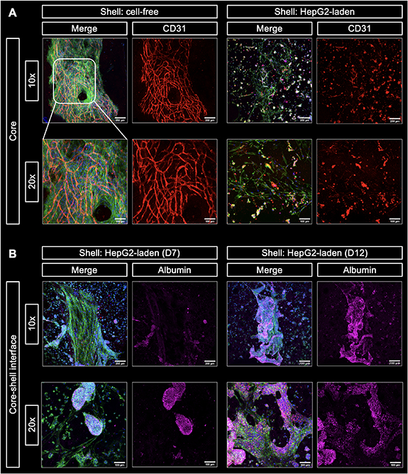
Figure 9. Influence of HepG2-laden shell on the pre-vascular network formation in the HUVEC-NHDF-laden CFG core and the role of fibroblasts. (A) Comparison of pre-vascular network formation in the core of bioprinted core–shell constructs with cell-free and HepG2-laden plasma-algMC shell. Representative cLSM images of the core of the constructs at day 15 of culture in CCM + VEGF. Defined CD31-positive vascular-like networks (red) were formed by HUVEC when bioprinted with a cell-free shell. In the presence of HepG2 in the shell, HUVEC remained mostly as single cells. NHDF networks (cytoskeletal F-actin stained in green) appeared denser in constructs with cell-free shell. The merge images additionally show nuclei (blue). Scale bars 10× = 200 μm, scale bars 20× = 100 μm. (B) Interaction between HepG2 and NHDF at the core–shell interface of triple culture constructs consisting of a HUVEC-NHDF-laden CFG core and a HepG2-laden plasma-algMC shell. Representative cLSM images of the core–shell interface of the constructs at day 7 and 12 of culture in CCM + VEGF. An initial interaction was observed at day 7 that resulted in close contact of both cell types within the clusters at day 12 of culture. Cells were stained for albumin (magenta; visible exclusively in hepatocytes), cytoskeletal actin (green), and nuclei (blue). Scale bars 10× = 200 μm, scale bars 20× = 100 μm.
Download figure:
Standard image High-resolution imageNoticeably, a dense network of fibroblasts (observed by cytoskeletal actin) was present in the core if the shell was cell-free, whereas only a sparse fibroblast network was observed in the core when HepG2 were included in the shell (figure 9(A)). It has been reported that to form vascular-like structures HUVEC not only require secreted soluble proteins but also direct physical support from fibroblasts [62]. The sparse fibroblast network in the presence of HepG2 was most likely not sufficient to support the formation of vessel-like structures. Thus, we assume that the disturbed pre-vascular network formation might be not a direct effect of the HepG2 but indirectly caused via a reduced fibroblast density in the core.
Given that fibroblasts are known to interact with both HUVEC and HepG2, it was hypothesized that the sparse fibroblast network in the core observed under the presence of HepG2 in the shell (figure 9(A)), could be the result of a strong interaction between hepatocytes and fibroblasts at the core–shell interface. To evaluate this hypothesis, bioprinted triple-culture constructs of the same experiment were re-imaged in different focal planes. Figure 9(B) shows cellular structures at the core–shell interface over time. At day 7, a defined fibroblast network was observed (indicated by stained cytoskeletal actin) with hepatocyte clusters (indicated by stained albumin) coming into contact with the fibroblasts. By day 12, the interaction between hepatocytes and fibroblasts appeared to be closer, forming mixed clusters; the exclusive expression of albumin by hepatocytes allowed for the differentiation between both cell types. A physical interaction between HepG2 and different types of fibroblasts, which includes migration of HepG2 towards fibroblasts and vice versa, as well as the formation of thick strands that resemble the hepatic cords formed during liver development has recently been reported also by others [63].
These observations indicate that hepatocytes and endothelial cells compete for the supportive fibroblasts. In this particular experiment, the stronger interaction observed between HepG2 and fibroblasts likely resulted in a decreased availability of the fibroblasts as structural support for the HUVEC in forming pre-vascular structures.
Based on these findings, it was hypothesized that a lower density of HepG2 would reduce the competition with HUVEC. This was experimentally proven by using a significantly lower (30-fold) concentration of hepatocytes encapsulated in the shell compartment of triple culture bioprinted core–shell constructs while all other parameters including batch of HUVEC and HepG2 were similar to the experiment shown in figure 9. Imaging of the core–shell interface revealed regions with and regions without hepatocyte clusters within the same construct, due to the lower concentration of HepG2 used. Figure 10(A) depicts a representative image of a HepG2-rich region, where hepatocytes grew into large clusters that expressed albumin and were in close contact with pre-vascular structures. Figure 10(B) depicts a representative image of a HepG2-poor region, where only vascular-like structures were visible. Whereas the pre-vascular networks formed in regions without close contact with HepG2 clusters were dense and defined, the CD31-positive staining appeared less intense and defined in direct contact to the hepatocyte clusters (figure 10(A)). This observation might be owed to limitations of cLSM analysis of these core–shell constructs: imaging of the prevascular network could have been hindered as a result of being out of the focal depth of the microscope when growing around the HepG2 clusters. Moreover, the dense HepG2 clusters may have prevented the excitation light from reaching the region below during imaging. Imaging different regions of triple culture constructs confirmed the close contact between pre-vascular networks and HepG2 clusters (figures 10(C) and (D)): pre-vascular structures were not disrupted by the HepG2 aggregates but rather surrounded them (indicated by the white arrows). Again, this hindered imaging of the complete pre-vascular network since it appeared in different imaging planes.
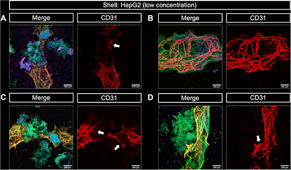
Figure 10. Cellular interaction between NHDF-HUVEC encapsulated in a CFG core and HepG2 encapsulated in a plasma-algMC shell in a 3D bioprinted triple culture model. Representative cLSM images of the core–shell interface of triple culture bioprinted constructs after 15 d of culture in CCM + VEGF. (A) HepG2 clusters expressing albumin (magenta) in close contact with CD31-positive pre-vascular structures formed by HUVEC (red). (B) CD31-positive pre-vascular structures formed by HUVEC in a HepG2-free region of a triple culture bioprinted construct. (C) and (D) CD31-positive pre-vascular structures (red) in close contact with HepG2 clusters. Structures appear yellow in the merge image because of the overlay of green and red. Merge images additionally show stained cytoskeletal F-actin (green) and nuclei (blue). The white arrows point at pre-vascular structures surrounding HepG2 clusters. Scale bars = 200 μm.
Download figure:
Standard image High-resolution imageA positive effect of HepG2 on HUVEC angiogenesis has been reported either by paracrine factors and exosomes [64] or physical contact with HepG2 [65]. In our core–shell bioprinted triple culture model, we observed an inhibition of HUVEC angiogenesis in the core if HepG2 were present in high density in the shell which is assumed to result from a competition between HepG2 and HUVEC for the supportive fibroblasts (figure 10). Based on this assumption and the insights from literature, a direct negative effect of HepG2 on vascularization is not to be expected. This was proven by a transwell assay in which HUVEC-NHDF were encapsulated in CF gels and cultured on inserts placed on top of HepG2-laden plasma-algMC constructs. The presence of HepG2 did not affect the ability of HUVEC to form pre-vascular structures (supplementary figure S5), indicating that HepG2 do not have a direct negative effect on angiogenesis.
3.3.3. Enhanced albumin secretion in the triple culture
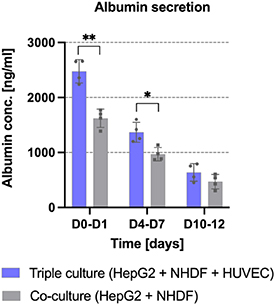
In our previous study, we demonstrated that the presence of NIH 3T3 fibroblasts in the core of core–shell constructs enhanced the proliferation and albumin expression of HepG2 encapsulated in the shell [11]; enhanced albumin secretion in presence of fibroblasts has also been reported [20, 66]. Beyond that, studies on co-culture models with HUVEC and HepG2 suggested that the presence of HUVEC results in enhanced viability [21] and enhanced albumin secretion [17, 67]. To evaluate whether the capacity of HepG2 to secrete albumin is further increased in presence of HUVEC, a quantitative evaluation of secreted albumin was performed in the current study for triple culture constructs consisting of HUVEC and NHDF in the CFG core and HepG2 in the plasma-algMC shell as well as for co-culture constructs consisting of NHDF in the CFG core and HepG2 in the plasma-algMC shell. As illustrated in figure 11, a significantly higher amount of albumin was produced and secreted at days 0–1 and 4–7 in the triple culture compared to the co-culture condition, suggesting that the presence of HUVEC in the core enhanced the differentiation of HepG2 encapsulated in the shell. Our results are in accordance with other studies: Lee et al investigated the albumin secretion of primary rat hepatocytes embedded in collagen gels as monoculture, co-culture with human fibroblasts and triple culture with human fibroblasts and HUVEC and found a gradual, significant increase in the co- and triple-culture [14]. We further observed that by day 12, the difference between both conditions was not statistically significant and that the secreted albumin concentration decreased over time. This effect has been reported for different 3D culture models of HepG2, showing a higher albumin secretion during the first 7 d of culture followed by a decrease over time [38]. Reduced albumin production has also been reported in large HepG2 aggregates, probably because of a lower oxygen concentration in the core of the spheroids [37]; this could be also a reason for the decrease over time observed in the present study.
Figure 11. Albumin secretion by HepG2 the shell compartment of bioprinted triple-culture and co-culture constructs. HepG2 cells were encapsulated in plasma-algMC shell, the CFG core were laden either with NHDF and HUVEC (triple culture conditions as shown in figure 8) or with NHDF only (co-culture condition) and cultured in CCM + VEGF. Albumin secreted into the supernatant was quantified at day 1, 7 and 12 of culture using ELISA (Mean ± SD, n = 4, *p < 0.05 and **p < 0.01). The time interval corresponds to supernatant collection times when medium was changed.
Download figure:
Standard image High-resolution image
3.4. Contribution to the field, limitations and outlook
In this study, we were able to establish a core–shell bioprinted triple culture model comprising hepatocytes (HepG2), endothelial cells (HUVEC) and supportive, matrix-forming fibroblasts (NHDF). Despite a certain competition of HepG2 and HUVEC for the supportive cells, we have demonstrated maintenance of the specific phenotype of all three cell types in this engineered 3D environment. Thus, the interaction between functional hepatocyte clusters and endothelial cells in their physiological state of organized vessel-like structures can be investigated with this triple culture model. This is an advance compared to other bioprinted, patterned hepatic co-culture systems in most of which only co-cultures of two cell types were investigated—either co-cultures of hepatocytes with fibroblasts [11, 20] or of hepatocytes with endothelial cells [17, 19, 21, 23]. Furthermore, even if endothelial cells were used, they could not show pronounced formation of pre-vascular structures [13, 17, 19, 23]. The core–shell bioprinted triple culture model allows the observation of more complex interactions between three cell types—as demonstrated by the competition of HepG2 and HUVEC for the fibroblasts in this study. Such effects are impossible or very difficult to detect in mixed triple-culture systems. Additionally, in contrast to bioprinted mixed triple-cultures [14, 15], the core–shell bioprinted triple culture has the potential to be further developed towards 3D models which truly mimic the micro-architecture of the liver sinusoid with a perfusable channel. Finally, the core–shell constructs containing a pre-vascularized core could be transferred to other tissue models; in that case, the fibroblasts as supportive cells could be replaced e.g. by mesenchymal stromal cells.
Nevertheless, while a complex and specialized system like the one described in this study has inherent limitations, these open up opportunities for further improvement. An important consideration is the use of HepG2 cells. Given the limited availability and complicated isolation of primary human hepatocytes (PHHs), the carcinoma cell line HepG2 is commonly used because of their genotypic similarities to PHH. However, their low metabolic capacities in comparison to PHH remain a limitation for in vitro models [68]. In this study, HepG2 cells grew into large cell clusters, which might result in a counterproductive effect. A possible solution could be to decrease the concentration of growth factors in the hydrogel by reducing the concentration of human blood plasma. On the other hand, a major achievement in this study was the development of a bioink based on natural and ECM-derivate components (the CFG bioink) that provided an optimal microenvironment for endothelial cells, as demonstrated by their ability to form pre-vascular networks and that is extrudable as core in core–shell constructs. However, an organizational pattern as the one in the liver sinusoid requires further development of the biofabrication approach. Finally, it is important to consider that due to its complexity the described model has an inherent variability that is difficult to control. As previously mentioned, aspects such as the combination of biological factors, different cell batches and human-derived components contribute to the variability of the system.
All in all, the triple culture system proved to be a useful model to study complex interactions in which different cell types remained functional. In a future approach, it would be interesting to develop a perfusable system (e.g. by using triaxial extrusion-nozzles) which resembles the native conditions of the liver sinusoid more closely. Similarly, the use of tissue specific cells (e.g. PHH, liver sinusoidal endothelial cells, stellate cells) would be valuable to establish a more physiological model. The human origin of all the cell types used in this model results in a complex system in which the components cannot be easily separated to evaluate their behavior by traditional quantitative assays. Thus, optimization of the analyses with tools that provide quantitative results is needed supplement the results presented in this study.
4. Conclusion
The results shown in this work indicate the successful fabrication of a complex in vitro triple culture model of the hepatic sinusoid. The core–shell structured constructs gained stability through the crosslinked alginate network in the shell; the functionalization of the shell bioink with fresh frozen plasma supported not only the embedded hepatocytes but additionally stabilized the ECM-based CFG core, most likely through the formation of a fibrin network across the core–shell interface during polymerization. As demonstrated, cells survived the extrusion-based coaxial printing process and the biomaterials used for both compartments appeared to be compatible with each other and support cell proliferation and function. HUVEC were able to form pre-vascular networks in the natural ECM-derived core compartment in the absence and presence of hepatocytes. HepG2 were able to grow into large clusters and migrate through the interface, where they were in close contact with and surrounded by pre-vascular networks. Interaction of the different cell types in the triple culture model was indicated by an enhanced HepG2 functionality in terms of albumin secretion in the presence of HUVEC, the necessity of supportive fibroblasts for angiogenesis, and the competing effect of HepG2. Thus, core–shell bioprinting was shown to be a valuable tool to study cell–cell-interactions and to develop tissue-like models.
Acknowledgments
The authors acknowledge the European Social Fund and the Free State of Saxony for the financial support of this study in the course of the Young Researchers Group IndivImp. We thank Kathleen Schütz and Anna-Maria Placht for excellent technical support, Dr Corina Vater for introduction in and support with the angiogenesis assay, Dr Anne Bernhardt, David Kilian, Dr Ashwini Rahul Akkineni as well as Dr Sarah Duin for their support regarding gene expression analysis, core–shell bioprinting and scientific discussions. We also thank the Core Facility Cellular Imaging (CFCI) of Technische Universität Dresden, Faculty of Medicine, for excellent advice, technical support and provision of the cLSM equipment.
Data availability statement
All the data that support the findings of this study are included within the article and the supplementary information files.
Author contributions
The manuscript was written through contributions of all authors. All authors have given approval to the final version of the manuscript. Conceptualization: R T, A L, M G; Experimental work and data analysis: R T, N C; Visualization: N C; Writing—original draft: R T, N C; Writing—reviewing and editing: R T, N C, M G, A L; Supervision: A L; Funding acquisition, Project administration, Resources: M G, A L.
Supplementary data (1.2 MB PDF)