

Abstract
The aim of this paper was to design and fabricate a novel composite scaffold based on the combination of 3D-printed polylactic acid-based triply periodic minimal surfaces (TPMSs) and cell-laden alginate hydrogel. This novel scaffold improves the low mechanical properties of alginate hydrogel and can also provide a scaffold with a suitable pore size, which can be used in bone regeneration applications. In this regard, an implicit function was used to generate some gyroid TPMS scaffolds. Then the fused deposition modeling process was employed to print the scaffolds. Moreover, the micro computed tomography technique was employed to assess the microstructure of 3D-printed TPMS scaffolds and obtain the real geometries of printed scaffolds. The mechanical properties of composite scaffolds were investigated under compression tests experimentally. It was shown that different mechanical behaviors could be obtained for different implicit function parameters. In this research, to assess the mechanical behavior of printed scaffolds in terms of the strain–stress curves on, two approaches were presented: equivalent volume and finite element-based volume. Results of strain–stress curves showed that the finite-element based approach predicts a higher level of stress. Moreover, the biological response of composite scaffolds in terms of cell viability, cell proliferation, and cell attachment was investigated. In this vein, a dynamic cell culture system was designed and fabricated, which improves mass transport through the composite scaffolds and applies mechanical loading to the cells, which helps cell proliferation. Moreover, the results of the novel composite scaffolds were compared to those without alginate, and it was shown that the composite scaffold could create more viability and cell proliferation in both dynamic and static cultures. Also, it was shown that scaffolds in dynamic cell culture have a better biological response than in static culture. In addition, scanning electron microscopy was employed to study the cell adhesion on the composite scaffolds, which showed excellent attachment between the scaffolds and cells.
Export citation and abstract BibTeX RIS
1. Introduction
Today, millions of patients lose their lives due to accidents and diseases in which they miss their tissues and organs. In this regard, tissue transplantation helps such people recover their lives and has increased life expectancy in society. However, some problems and challenges arise when tissue is transplanted, such as diseases, infections, and host rejection of the tissue. These problems and challenges need to be dealt with. In addition to previous challenges, tissue and organ deficiency is recognized as a significant public health challenge. To resolve these issues, the tissue engineering field has emerged as a strong and multidisciplinary field to help restore, improve, and maintain tissues and organs. The tissue engineering field is trying to potentially regenerate almost all tissues and organs of the human body, which would allow offering new treatments for diseases and injuries. Advances in tissue engineering have involved various research fields such as cell biology, biomaterial science, imaging, and characterization of cell and material interactions [1–4]. One of the most important stages in tissue engineering is the designing and fabrication of a scaffold, which performs some functions such as promoting cell–biomaterial interaction, providing cells with sufficient transport of gases, nutrients, and regulatory factors in order to assist in survival and proliferation of the cells, biodegradability, and to create the least degree of inflammation or toxicity in the body [1]. Therefore, the design and fabrication of novel and practical scaffolds have been widely considered by researchers [5, 6].
Additive manufacturing, also known as 3D printing, refers a process in which an object is built layer-by-layer and is one of the most novel technologies that has been employed in different applications [7–9]. Due to the high potential of 3D printing technology, complex structures that would be difficult to make using traditional methods, such as casting and forging, can now be easily made [7–13]. Besides industrial applications, 3D printing has made its way into biomedical applications and helps researchers design patient-specific constructs that were previously challenging with traditional methods. For example, in a study to treat mallet finger injury, a personalized finger split was designed and printed, which provided more comfortability and breathability and less sweating for the patient [14]. In another study, a patient-specific arm cast was built with 3D printing technology, which was more accurate, lighter, durable, and had better airflow circulation for the patient [15]. Besides applying 3D printing technology in external body applications, researchers have done much research in which they have used 3D printing technology in in-vitro and in-vivo applications, which in these cases is called 3D-bioprinting. For example, because of the importance of proposing treatment for skin disease, many people suffer from unhealed skin wounds. Efforts have been made to 3D bioprint complex tissue of the skin [16–20].
Researchers have considered bone as another tissue due to its importance for body movement and locomotion and significant duties in the body, such as the production of blood cells and the storage of minerals and growth factors [21]. On the other hand, bone has significant potential to repair its wound, and self-repair ability when it is smaller than critical size defect (CSD). However, when the size of the defect is larger than the CSD, it is necessary to employ surgical intervention [22]. One of the most novel methods that have been employed in bone regeneration is scaffold-based tissue engineering, which combines biomaterials and cells to recover the required functions of tissues [21, 23–25]. In this regard, researchers are trying to design and fabricate a scaffold with suitable shape, pore size, porosity, biocompatibility, degradability, and mechanical properties to provide proper cell adhesion, proliferation, and also avoid stress shielding [21, 23, 26, 27]. In a study [28], an alginate microparticle and microfiber scaffold were built, and their mechanical and morphological features were studied. It was shown that both scaffolds have suitable mechanical properties for their use as bone tissues. Also, the biocompatibility of scaffolds was investigated in an in-vitro study. In another study [29], the additively manufactured polylactic acid (PLA)-based composite scaffold was fabricated with fused deposition modeling (FDM) 3D printing, and the PCL-nano-hydroxyapatite (nHA) and PCL-multiwalled carbon nanotubes (MWCNT) were added as additive parts to scaffolds. This novel scaffold enabled researchers to combine the additive parts with 3D printed structures at ambient temperatures, which this method helps to incorporate drug or heat-labile bioactive molecules in the scaffolds. In another study [30], the composite alginate/fluorenylmethoxycarbonyl-diphenylalanine hydrogel was fabricated for bone regeneration purposes. High biocompatibility and suitable mechanical properties, which were like the native extracellular matrix (ECM), were the achievements of fabricated scaffold that showed its ability in bone regeneration applications. Three-dimensional-printing alginate/gelation scaffold was investigated in another study [31], in order to improve the mechanical and biological properties, the nano apatite coating was applied to the scaffold. It was found that the mechanical properties of the coated 3D-printed scaffold were improved compared to the uncoated scaffold.
Moreover, nano-coating has significantly induced the proliferation and osteogenic differentiation of rat bone marrow stem cells. Since bone tissue has a complex structure, some researchers use function-based modeling, due to its accuracy and controllability, to create tissue bone models that mimic native bones [32, 33]. Researchers use different approaches to design complex geometries [34–36]. Triply periodic minimal surfaces (TPMSs) are a class of function-based structures that have already been extensively considered due to their unique collections of properties like high surface-to-volume ratio, stiffness-to-weight ratio, and cellular interconnectivity [37–40]. As a first attempt, Rajagopalan and Robb employed TPMS structures as bone tissue scaffolds and evaluated the mechanical properties and cell seeding viability of TPMS structures [41]. Other researchers then used TPMS structures for bone tissue engineering purposes. For example, in a study, the Ti6Al4V TMPS structure was built to mimic bone tissue. The mechanical properties and osteointegration ability of the scaffold verify the potential of the fabricated scaffold for bone regeneration purposes [38]. Three-dimensional printed PLA-based TPMS structures were fabricated in another study [42]. It was demonstrated that pore size and interconnectivity play a significant role in the differentiation of pre-osteoblastic cell lines.
The literature review shows that researchers are always trying to propose new bone tissue scaffolds with better mechanical and biological properties that are cost-effective and easy to build. The TPMS scaffolds are good candidates for bone regeneration. However, their printing with the FDM process cannot provide us with a suitable pore size due to their geometrical complexity. On the other hand, alginate hydrogel has low mechanical properties, and the combination of TPMS scaffolds and alginate hydrogel can produce a novel composite scaffold that can overcome both the mentioned problems. Therefore, in this research, PLA-base TPMS scaffolds are 3D-printed, and cell-laden alginate hydrogel is used as a reinforcement phase. In this regard, since the native microstructure of bone is complex, a function-based model is employed to create a bone scaffold that can mimic the native bone. Figure 1 shows the schematic shape of the scaffold-based approach used in this research for bone tissue regeneration. The micro computed tomography (micro-CT) is performed on 3D-printed TPMS scaffolds to specify their real geometry and pore distribution. The mechanical properties of 3D-printed TPMS scaffolds are investigated based on their real and nominal geometry experimentally. A finite element model (FEM) is developed to simulate the mechanical behavior of scaffolds under compression tests. Also, stress–strain curves of scaffolds are obtained based on equivalent volume and finite element approach. Biological assays are also used to assess the biological response of composite scaffolds. Since static cell culture does not have good mass transportation and cannot stimulate the cell with mechanical loading, in this study, a dynamic cell culture system is used to improve these deficiencies. To create a 3D-dynamic cell culture condition, a perfusion bioreactor is finally designed and fabricated. The results show that dynamic cell culture can promote cell proliferation, and the proposed composite scaffolds have a good biological response in terms of cell viability, cell adhesion, and cell proliferation. Due to the absence of similar methodology and results in the specialized literature, this paper is likely to fill a gap in state of the art for this problem and provide pertinent results that are instrumental toward the reliable regeneration of bone tissues with 3D bioprinting and high performance.
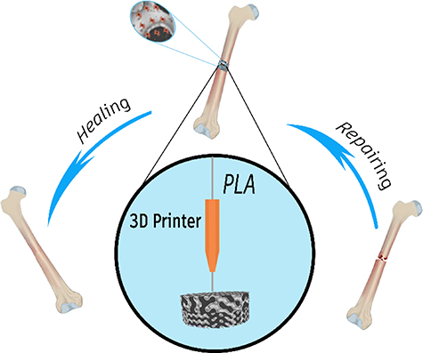
Figure 1. A schematic shape of the scaffold-based approach for the bone regeneration application.
Download figure:
Standard image High-resolution image2. Materials and methods
2.1. Materials
Calcium chloride-dihydrate and sodium alginate were obtained from Merck, Dulbecco's Modified Eagle Medium (DMEM), and fetal bovine serum were purchased from GIBCO. Glutaraldehyde and osmium tetroxide were obtained from Sigma Aldrich, and PLA filament was purchased from Youso.
2.2. 3D printing of PLA-based TPMS structure
A function-based method is developed to design and fabricate different scaffolds with various shapes and pore sizes to generate bone scaffolds. Among function-based models, the TPMS, which have zero mean curvature and large surface areas, are used due to their high potential in designing scaffolds. The gyroid surface (G-type) is applied to design the scaffold, and its function can be expressed as equation (1):
where x, y, and z are spatial coordinates, and density and the unit cell size can be controlled by parameters  and
and  , respectively.
Different values of  and
and  were chosen to obtain diverse circular scaffolds in different volumes with dimensions of
  diameter and
  height. Figure 2 demonstrates the computer-aided design (CAD) of designed scaffolds with different values of density that have been obtained by changing
  and
and  parameters.
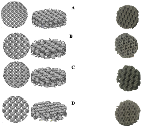
Figure 2. Top and isometric view of designed TMPS scaffolds for (A)  (B)
(B)  (C)
(C)  (D)
(D)  .
.
Download figure:
Standard image High-resolution imageOne of the important features in the bone scaffolds is the porosity, which significantly affects the mechanical and biological performance of the scaffold. Therefore, to measure this feature, the relative density can be used as expressed in equation (2):
where  and
and  are the density of a scaffold and bulk material, respectively.
The calculated values show that the amount of  and
and  values have a direct relationship with relative density, meaning that increasing these values leads to an increase in relative density. The calculation of nominal relative density for the designed scaffold is presented in table 1. Since the geometry of designed and printed CAD is different, the term nominal is used to refers to designed CAD.
Table 1. Calculated relative density for designed TPMS scaffolds.
| Scaffold | Nominal scaffold volume ( ) ) | Nominal relative density |
|---|---|---|
| A | 557 | 64.5% |
| B | 442 | 73.1% |
| C | 434 | 72.3% |
| D | 394 | 75% |
After designing scaffolds, the 3D-printing process was employed to fabricate scaffolds. In this regard, the FDM process with PLA filament was chosen, which is one of the simplest and most practical methods among 3D printing methods. During this process, the filament is deposited according to the CAD data in a layer-by-layer process to fabricate a 3D scaffold. The printing parameters, such as printing speed, nozzle, and bed temperature, have a significant effect on the final properties of the scaffold, which were set at 5  ,
,  and
and  , respectively. Figure 3 depicts the 3D-printed scaffolds.
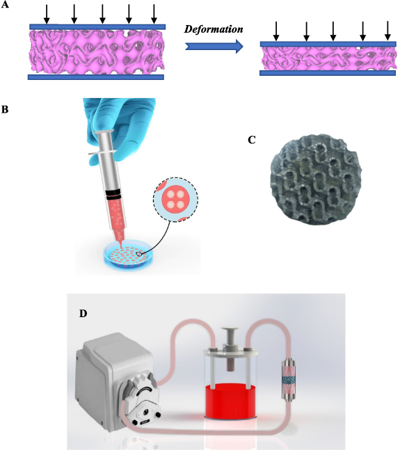
Figure 3. (A) Schematic illustration of the compression test. (B) A schematic illustration of the fabrication of a composite scaffold. (C) A fabricated composite scaffold D. (D) The profusion bioreactor designed in this study.
Download figure:
Standard image High-resolution image2.3. Mechanical testing
The compression test was employed to investigate the mechanical properties of scaffolds. The loading was conducted at a 1 mm min−1 speed, which provides the static loading condition. Figure 3(A) illustrates the schematic shapes of the compressive test.
2.4. Cell culture for biological characterization
The cell line used in this study is SaOs-2 (NCBI Code: C453) which was provided by the National Cell Bank of Iran (Pasteur Institute of Iran). The SaOs-2 cell line was established from an 11 year-old Caucasian female with osteogenic sarcoma. The SaOs-2 cancerous cell line was cultured in RPMI 1640 (Sigma, Germany) supplemented with 10% heat-inactivated fetal calf serum (Gibco, USA), 2 mM L-glutamine (Sigma, Germany), 5 × 10⁻⁵ mM 2-mercaptoethanol (Sigma, Germany), 10 mM 4-(2-Hydroxyethyl)-1-piperazineëthanesulfonic Acid (HEPES) (Sigma, Germany), and 40 μg ml−1 gentamicin (Sigma, Germany). Cells were incubated in a humidified atmosphere at 37 °C in 5% CO2.
2.5. Preparation of cell-seeded composite scaffolds
In order to prepare an alginate hydrogel, a solution of 1% (W/V) alginate-media culture (DMEM) was prepared and then stirred for 30 min. The resulting solution was then passed through a filter 0.22 µm to sterilize it. After sterilizing the alginate-DMEM solution, for each scaffold, the volume of 500 µl of the solution was mixed with 500 µl of cell suspension containing 2 million cells. Then the resulting solution was stirred to obtain a homogeneous solution. Figure 3(B) illustrates a schematic picture of the mentioned process.
After preparing the alginate-DMEM solution loaded with cells, the 3D-printed scaffolds were immersed in CaCl2 10% solution, and the alginate-DMEM-cell solution was injected into the 3D-printed scaffold with the syringe. The injected alginate-DMEM-cell solution was crosslinked during this process, and the gel formed in the porous media. Therefore, in this process, we obtain a 3D-printed scaffold in which the alginate-loaded cell is incorporated into porous media. Figure 3(C) illustrates a schematic of the process, and figure 6 demonstrates a fabricated composite scaffold that was made.
2.6. Dynamic culture vs static culture
In order to create a dynamic culture condition, a profusion bioreactor was designed and fabricated. In this way, the profusion bioreactor consisted of a culture room, a peristaltic pump (BIO-RAD Econo EP-1), a silicone pipe, and a culture medium reservoir. The culture room was fabricated so that the composite scaffolds could stand up in the culture room, and a uniform flow of fluid could flow through the culture room. In this regard, since the shape of scaffolds is cylindrical, the culture room was designed and fabricated in the cylindrical shape. Moreover, the inner radius of the culture room was designed so that the scaffolds can be placed in the culture room with the contact force between the scaffold and the culture room, which prevents moving scaffolds due to fluid flows. In addition, to prevent side effects that can change the result of the experiments, the dimension of the fabricated culture room after fabricating was carefully controlled. The dimensions of the culture room were a cylinder with a diameter of  and a height of
  and, the inlet and outlet of the culture room were chosen with a diameter of
  . Figure 3(D) displays the profusion bioreactor designed in this work. Moreover, the flow rate was chosen at
  for dynamic cell culture, which such a flow rate range has been used by other researchers [43, 44]. The scaffolds chosen for dynamic culture were inserted into the fabricated culture room, and static scaffolds were placed on plates. After that, they were incubated at 37 °C with 5% CO2.
2.7. Osteoblast-like cells (SaOs-2) seeding into composite scaffolds and evaluation of proliferation by MTT assay
All scaffolds were sterilized by immersing them in ethanol for 2 h, and then they were washed three times in phosphate-buffered saline (PBS), and finally, they were exposed to UV light for half an hour. The SaOs-2 cell line was seeded onto the scaffolds at a density of  cells per scaffold. For static scaffolds, the cell seeding was so that all
  cells were suspended in 1 ml culture media, and every 15 min, 15 μl of cell-culture media solution was seeded into scaffolds, and then the scaffold was incubated for 15 min. For composite scaffolds, the cells were loaded onto the alginate hydrogel, and then the alginate was injected into scaffolds so that the CaCl2 caused crosslinking of the hydrogel. The MTT test was performed after 7 d to determine the cell viability in scaffolds. After 7 d, the scaffolds were rinsed with PBS and then placed into a six-wells plate, including the ratio of 5:1 culture medium, and MTT (with 5 mg ml−1 concentration in PBS) was incubated for 2–3 h at 37 °C. Following, 500 μl of dimethyl sulfoxide (DMSO) was added to the wells, and the scaffolds were thoroughly washed to allow the complete release of color, and the enzyme-linked immunosorbent assay (ELISA) reader read the absorbance at 570 nm.
2.8. Metabolic control
The media culture was obtained from reservoirs and analyzed. Lactate and glucose concentrations were measured in cell culture supernatants using a spectrophotometric method with Autoanalyzer (BT3000) and biosystem kit. The aldehyde group of glucose can undergo condensation with aromatic compounds to yield a colored product. The enzyme glucose oxidase reacts with glucose, water, and oxygen to form gluconic acid and hydrogen peroxide. The hydrogen peroxide can then be used to oxidize a chromogen to estimate the amount of glucose present. Lactic acid also be measured enzymatically by using the enzyme lactic dehydrogenase (LDH) with the coenzyme nicotinamide adenine dinucleotide (NAD+) according to the following reaction.
CH3CHOHCOO− + NAD  LDH CH3COCOO− + NADH+ + H+
NADH formed was then measured by the spectrophotometric method.
Also, all test were replicated three times.
2.9. Scanning electron microscopy (SEM) of the osteoblast-like cells (SaOs-2) composite constructs
The scaffolds' surface was observed by SEM to investigate cell adhesion. In this regard, cell-seeded scaffolds were immersed in a 2.5% glutaraldehyde mixture for 24 h. Then, the scaffolds were rinsed with PBS and placed in 1% osmium tetroxide in 0.1 M sodium cacodylate for 2 h. Then, scaffolds were dried out with an ethanol solution of 20%, 40%, 60%, and 80%. Next, to evaluate cell shape, adhesion to the scaffold, and ECM presence, the scaffolds were cut from their width, and Au was coated on their surfaces.
2.10. Statistical analysis
The mean standard deviation is used to represent biological data. The statistical analysis was conducted by one-way analysis of variance using SPSS software. Statistical significance was accepted as P < 0.001.
3. Results
3.1. Micro-CT analysis
The microstructure and geometry of tissue scaffolds significantly affect their mechanical properties and functionality for in-vitro and in-vivo studies. Micro-CT provides the opportunity to analyze the microstructure of 3D-printed scaffolds, and it also helps to build the real 3D geometry of scaffolds, as due to the printing condition and precision of the 3D printing setup, the real and nominal geometry of scaffolds is different from each other. In this research, the micro-CT is employed to obtain the microstructure of 3D-printed scaffolds and the real 3D-CAD of TPMS scaffolds. In this regard, a desktop micro-CT scanner was used (LOTUS-NDT, Behin Negareh Co.). The LOTUS-NDT has a cone-beam micro-focus x-ray source and a flat panel detector. The x-ray tube voltage and its current were set to 80 kV and 60 μA. No added filtration was used in this study. The total scan time for each sample was 2.5 h, and the resolution was 15 µm. The LOTUS NDT-ACQ software controlled all the protocol settings processes. Figure 4 shows the top view of 3D-printed scaffolds' micro-CT images, and table 2 shows the real relative density for 3D-printed TPMS scaffolds.
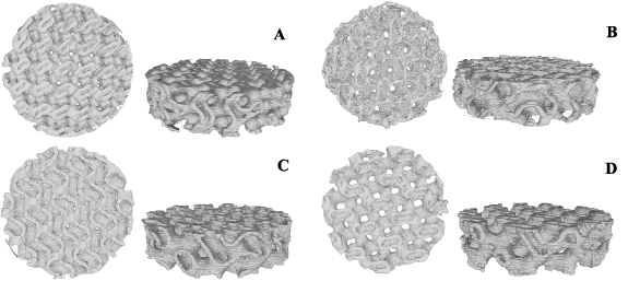
Figure 4. Top and isometric view of the real geometry of TMPS scaffolds A–D for (A)  (B)
(B)  (C)
(C)  (D)
(D)  .
.
Download figure:
Standard image High-resolution imageTable 2. Calculated relative densities for printed TPMS scaffolds.
| Scaffold | Real scaffold volume ( ) ) | Real relative density |
|---|---|---|
| A | 755 | 52.0% |
| B | 607 | 61.3% |
| C | 635 | 60.0% |
| D | 569 | 64.0% |
According to the obtained results from the micro-CT technique, the values of actual relative density are lower than nominal values, which means the printed scaffolds have a smaller pore size than the designed scaffold due to the inaccuracy of the FDM printing process. Figure 5(A) shows the comparison between the real and nominal density of scaffolds. Also, figure 5(B) presents the average pore size for different printed scaffolds, in which scaffold A has the smallest average pore radius at 362.68 µm, and scaffold D has the largest value at 591.27 µm.
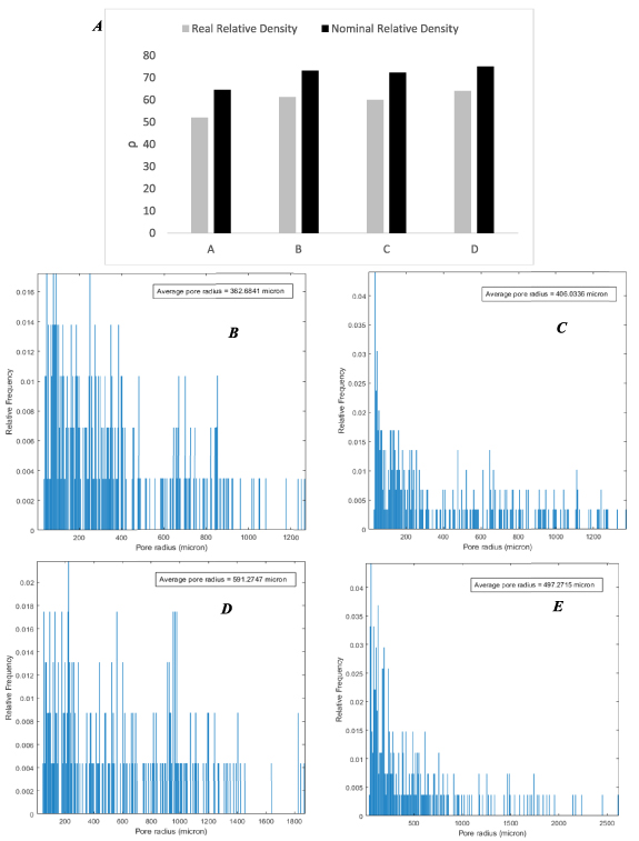
Figure 5. A comparison of the nominal and real geometry of 3D-printed scaffolds (A), relative frequency of distributed pores based on their pore sizes for printed scaffolds A–D (B)–(E).
Download figure:
Standard image High-resolution image3.2. Mechanical properties of scaffolds
3.2.1. Force–displacement curves
In order to determine the mechanical properties of alginate hydrogel, a cylindrical sample of hydrogel with dimensions of 10 mm and a height 10 mm was prepared, and the compressive young modules of alginate were obtained by using the compressive test, whose results are presented in figures 6(A) and (B). It is seen that alginate has poor mechanical properties, especially in the smaller strains. In the larger strains, since the alginate hydrogel loses its water and leads to a dry body, it will be stiffer than the smaller strain. For this tested sample,  is the strain that mechanical behavior experiences with a sudden sharp end, which shows that it loses its water.
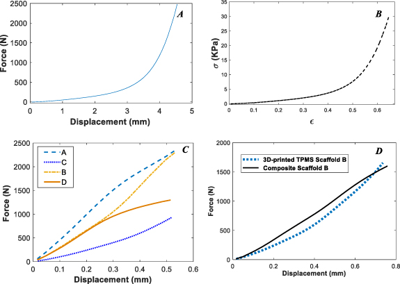
Figure 6. Force–displacement and stress–strain curves for the alginate hydrogel (A)–(B), force–displacement curves for 3D-printed scaffolds A–D. (C) A comparison of force–displacement curves for 3D-printed TPMS scaffold B and composite scaffold B (D).
Download figure:
Standard image High-resolution imageAlso, force–displacement curves for 3D-printed TPMS scaffolds A–D are shown in figure 6(C). As can be seen, scaffold A has more mechanical resistance than other scaffolds, which is due to its lower relative density. In small deformation or elastic regime, the mechanical response of scaffolds is inversely related to relative density. The smaller the relative density, the higher the mechanical strength.
Next, the mechanical properties of the 3D-printed TPMS composite scaffolds with embedded alginate hydrogel are examined. As an example, the force–displacement curve of scaffold B with and without alginate hydrogel is presented in figure 6(D). Since the alginate hydrogel has poor mechanical properties, it is seen that it does not affect the mechanical properties of composite scaffolds, and the printed scaffold determines the mechanical behavior of the composite scaffold. For all A–D cases, the force–displacement curves of composite scaffolds and 3D-printed scaffolds are observed to be close to each other, and therefore, they are not reported.
3.2.2. Stress–strain curves
Providing stress–strain curves can help researchers gain deep knowledge about the structure's performance while eliminating the effect of geometry and material volume. Based on the force–displacement curve results, we can only know about the structure's behavior without considering the volume of the structures, and often more materials applied, lead to better performance under mechanical loading. Therefore, to better understand the behavior of 3D-printed TPMS scaffolds and provide researchers with such an opportunity, stress–strain curves will be reported next. However, since the 3D-printed TPMS scaffolds are porous media, presenting a stress–strain curve for them is challenging work. In this regard, based on the two approaches, the stress–strain curves for 3D-printed scaffolds are obtained in next division.
3.2.2.1. Equivalent volume
By considering the fact that only the body part of the porous media scaffolds is involved in withstanding the mechanical load, the equivalent body or virtual body can be defined so that at the same effective gage length, the virtual body must be defined in the form of a bulk volume whose volume is equal to the porous media scaffold. Figure 7(A) shows a schematic of this approach.
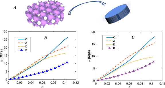
Figure 7. A schematic of the equivalent volume approach (A), stress–strain curves for printed TPMS scaffolds A–D based on their nominal equivalent volumes (B), stress–strain curves for printed TPMS scaffolds A–D based on their real equivalent volumes (C).
Download figure:
Standard image High-resolution imageGiven the described method, the effective area of printed scaffolds can be defined based on their nominal and real geometries, as reported in table 3.
Table 3. The effective area of scaffolds based on the equivalent volume method.
| Scaffold | Nominal 
| Real 
|
|---|---|---|
| A | 111.4 | 151 |
| B | 88.4 | 121.4 |
| C | 86.8 | 127.4 |
| D | 78.8 | 113.8 |
The results of stress–strain curves based on equivalent volumes are illustrated in figure 7. As can be observed in figures 7(B) and (C), scaffold C, which had the worst performance in the force–displacement curve, has the best performance based on both nominal and real geometry in terms of the stress–strain curve. Moreover, scaffold B, which had the second-best strain–stress curve performance, has the weakest performance among printed TPMS scaffolds.
3.2.2.2. Finite element method
The Abaqus FEM software has been employed to investigate the effective area of 3D-printed TPMS scaffolds. In this regard, based on their nominal and real geometries, which were obtained from micro-CT images, the FEM has been created, and their mechanical behaviors under compressive tests have been investigated. In order to investigate the mechanical behaviors of the filament used in the 3D printing of TPMS scaffolds, a cylindrical bulk material with dimensions of 20 mm in diameter and 20 mm in height was 3D-printed and evaluated under a compressive test figure 8(A). Figure 8(B) illustrates the stress–strain curve of bulk PLA.
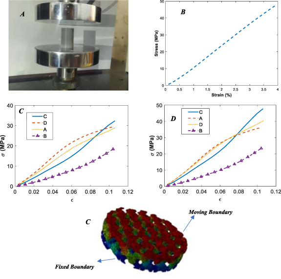
Figure 8. Bulk sample under compression (A), stress–strain curve for bulk PLA (B), stress–strain curves for printed TPMS scaffolds A–D based on the finite element simulation approach for nominal geometries (C), for real geometries (D), applied boundary conditions to the FEM (E).
Download figure:
Standard image High-resolution imageThe nominal and real geometries were meshed by surface mesh tools, and then the surface mesh was converted to volume mesh and imported to Abaqus FEM software. The boundary conditions of the problem were such that the upper face was fixed, and the lower boundary was chosen as the moving boundary. Figure 8(E) displays the real geometry of 3D-printed scaffold B with determining boundary conditions.
By applying a displacement to the scaffold, a global strain on the scaffold is defined as:
In which d and h show the scaffold's displacement and height, respectively.
By considering the constitutive equation in the elastic region, the obtained mechanical properties for PLA bulk, and the resulting force from finite element analysis, the effective area can be defined as:
Table 4 presents the calculated effective areas based on the finite element simulation approach for both nominal and real geometries.
Table 4. The effective area of scaffolds based on a finite element simulation approach.
| Scaffold | Nominal based FEM 
| Real based FEM 
|
|---|---|---|
| A | 81 | 58 |
| B | 51 | 40 |
| C | 71 | 48 |
| D | 44.33 | 36 |
Figures 8(B) and (C) demonstrate the stress–strain curves obtained from the finite element simulation approach for both nominal and real geometries. As seen in figure 8(C), which shows the stress–strain curves based on nominal geometry, scaffold D has the highest performance in the smaller strains. However, scaffold C shows better performance than other printed TPMS scaffolds in the larger strains. In this approach, scaffold B, similar to the previous approach, has the worst performance. In real geometry, scaffolds A and D have similar behavior, although their relative density is different from each other. Using real geometries can provide a precise understanding of the scaffolds' behaviors since it can consider the printing quality and geometries anomalies created in the scaffolds during printing. Overall, scaffold A has a better mechanical response than other scaffolds in terms of stress–strain and the force–displacements curve.
Also, the results of the above stress–strain curves are presented in table 5.
Table 5. Young modulus of all scaffolds based on different presented approaches.
| Scaffolds' name | Number of specimens | Calculation method | Young modules | Standard deviation (SD) |
|---|---|---|---|---|
| Pure alginate hydrogel | 3 | — | 10 KPa | 3.05 KPa |
| Scaffold A | 3 | Nominal equivalent area | 181 MPa | 8.18 MPa |
| Scaffold A | 3 | Real equivalent area | 145 MPa | 6.55 MPa |
| Scaffold A | 3 | Finite element approach-based nominal geometry | 250 MPa | 11.30 MPa |
| Scaffold A | 3 | Finite element approach-based real geometry | 350 MPa | 15.82 MPa |
| Scaffold B | 3 | Nominal equivalent area | 90 MPa | 11.23 MPa |
| Scaffold B | 3 | Real equivalent area | 68 MPa | 8.49 MPa |
| Scaffold B | 3 | Finite element approach-based nominal geometry | 163 MPa | 20.35 MPa |
| Scaffold B | 3 | Finite element approach-based real geometry | 218 MPa | 27.20 MPa |
| Scaffold C | 3 | Nominal equivalent area | 250 MPa | 6.42 MPa |
| Scaffold C | 3 | Real equivalent area | 163 MPa | 4.19 MPa |
| Scaffold C | 3 | Finite element approach-based nominal geometry | 310 MPa | 7.97 MPa |
| Scaffold C | 3 | Finite element approach-based real geometry | 436 MPa | 11.21 MPa |
| Scaffold D | 3 | Nominal equivalent area | 145 MPa | 6.02 MPa |
| Scaffold D | 3 | Real equivalent area | 90 MPa | 3.74 MPa |
| Scaffold D | 3 | Finite element approach-based nominal geometry | 254 MPa | 10.55 MPa |
| Scaffold D | 3 | Finite element approach-based real geometry | 363 MPa | 15.08 MPa |
3.3. Biological evaluation of composite scaffolds
In order to evaluate of biological response of the fabricated scaffolds, the composite scaffold A, whose scaffold without hydrogel has the best mechanical properties in terms of stress–strain and force–displacement curves, was chosen, and its biological response was compared with that without alginate hydrogel. For simplicity, the first and second scaffolds are called A and A1, respectively.
3.3.1. Metabolic control in cell culture
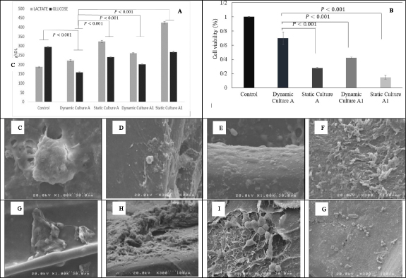
Lactate accumulation in mammalian cell culture often adversely affects culture performance. On the other hand, glucose is the primary energy source for cells, and over time, cells consume glucose. Therefore, to control cellular metabolism during culture, two variables, lactate, and glucose, were controlled and reported after the third day. As shown in figure 9(A), the value of lactate for four scaffolds has been increased. Scaffold A with dynamic culture has the lowest value of lactate compared to other scaffolds. Also, the value of reported glucose shows that scaffold A with dynamic culture has the lowest value of glucose. Overall, the reported data reveals that scaffold A with dynamic culture has a better culture performance than other scaffolds.
Figure 9. The value of lactate and glucose after the third days (A), results of the MTT test (B) SEM micrograph of the SaOs-2 morphology and ECM secretion on composite scaffolds A and A1, (C) and (D) scaffold A with a dynamic culture, (E) and (F) scaffold A with static culture, (G) and (H) scaffold A1 with static, (I) and (J) scaffold A1 with dynamic.
Download figure:
Standard image High-resolution image
3.3.2. Evaluation of SaOs-2 proliferation by MTT assay
Figure 9(B) shows MTT results of SaOs-2 culture on scaffolds in different conditions. The 2D-cell culture was used as a control. As the results indicate, the dynamic culture of the cells in the designed perfusion bioreactor exhibited higher proliferation in comparison to static culture. In addition, MTT results of cell seeding of the composite scaffolds show more proliferation in both dynamic and static culture compared to the scaffold without alginate. Perfusion bioreactors are designed to apply fluid flow in vitro to improve the mass transport of culture medium to the resident cells and apply mechanical forces to cells. Such a mechanical shear force stimulates cellular proliferation via integrin-mediated mechanotransduction [45].
3.3.3. Electron microscopy images of SaOs-2 constructs
SaOs-2 cell line is one of the most suitable alternatives to human osteoblast cells, especially in terms of alkaline phosphate activity [46, 47] and stem cell attributes [48]. In addition, SaOs-2 cell line has been shown to have different cell morphology on different substrates [49, 50]. Also, extracellular matrix secretion has a drastic role in tissue engineering, and for this osteosarcoma cell line has its function in subsequent cancer progression and metastasis [51]. From figure 9(C–G), it can be concluded that the cells successfully proliferated and secreted the extracellular matrix.
Alginate hydrogels have been extensively used as scaffolds for miscellaneous tissue engineering applications because of their excellent biocompatibility. However, the poor mechanical properties of alginate restrict its application for bone tissue engineering applications, and therefore it should be reinforced with appropriate agents [52–64]. From the figures, it can be observed that the alginate hydrogel structure is strengthened with the 3D-printed PLA structure. The results also indicate increased proliferation of the cells in a dynamic culture of cells compared to the static culture [65, 66].
4. Discussion
TPMS structures have been introduced as high-performance structures that can be manufactured with 3D printing methods such as FDM. These structures have many similarities with the native microstructure of the bone. In recent years, many researchers have worked on the mechanical properties of these structures. These studies have shown that due to the high ratio of volume to the surface of these structures, they are a good candidate for bone regeneration applications. The present study results have confirmed the excellent performance of TPMS scaffolds in bone regeneration applications. Pore size is one of the most important parameters that greatly affect the biological response of TPMS structures. Diez-Escudero et al [42] designed and printed bone scaffolds by using different 3D-printed TPMS structures. The results showed that the distribution and size of pores play a significant role in the growth and proliferation of the cell. Since they employed the FDM process for fabricating bone scaffolds, the minimum pore size obtained from this printing method was 650 µm. In the present study, the FDM method has been employed and based on micro-CT analysis, the minimum pore size is 362 µm from a technical point of view, this is an achievement. Since the optimal pore size for bone regeneration should be between 100 and 1500 µm, employing 3D-printed TPMS structures with the FDM process does not provide us with this minimum pore size. In this regard, researchers are searching for new solutions to overcome this limitation. Besides the pore size, the mechanical properties of TPMS structures are directly related to their application in bone regeneration applications. So, many researchers have worked on TPMS structures in view of their mechanical properties. In a study, the mechanical properties of TPMS scaffolds were investigated under compressive tests [67]. For this purpose, the stress–strain curves of the fabricated scaffold were evaluated in the nominal state. As mentioned in the result section, the nominal strain–stress curves are not exactly true, and this approach is associated with many errors. Reporting force–displacement curves for scaffolds or nominal stress–strain curves do not provide us with a deep understanding of the performance of fabricated scaffolds, and a more reasonable criterion is needed. In this research, which used compressive tests, two methods were used to get stress–strain curves for made-up scaffolds. In the equivalent, porous scaffolds were considered equivalent to bulk geometry provided that their volume was equal to each other. This method was done based on real and nominal geometries. The results obtained from the equivalent volume show that scaffolds that can withstand higher mechanical loads do not necessarily perform better. Scaffold C, which has the worst performance in the force–displacement curve, shows the highest mechanical performance in the stress–strain curve. But still, there are some deficiencies in this method that should be revised. Since some parts in the porous scaffolds do not withstand mechanical loads, but in the equivalent volume approach they have been considered, a method is needed to eliminate the effect of those parts from our calculation for stress–strain curves. The finite element simulation can be a potent approach to cover the mentioned deficiencies. Based on this approach, which has not been used in any previous research, based on the finite element simulation, the effective area for scaffolds was defined. In this regard, the micro-CT analysis was employed. The stress–strain curves for this study confirmed the result of the equivalent volume approach that scaffold C, which has the worst performance in force–displacement curves, has the best performance in stress–strain curves. However, these approaches are much different from each other in terms of stress value. For example, based on the equivalent approach, the amounts of stress for scaffold C are reported at 27 and 18 MPa for nominal and real geometry, respectively. However, these amounts are reported as 33 and 48 MPa based on the finite element approach. Since the finite element method can consider all aspects of the problem, its result is more reliable than the equivalent method. Therefore, calculating stress–strain curves based on the equivalent volume, which many researchers use, is associated with much error, and this method should be replaced with the finite element approach.
Alginate is one of the most important biomaterials that researchers in bone regeneration applications have widely used. Features that make alginate unique in bone regeneration applications are its biocompatibility, non-toxicity, non-immunogenicity, and biodegradability. Besides these advantages, there are some shortcomings in using alginate hydrogel in bone tissue regeneration, of which low mechanical properties can be mentioned as one. The experimental result of this research confirms this fact. So, using alginate hydrogel in tissues that require high mechanical properties has limited research and needs intervention.
Two problems were mentioned for alginate hydrogel and TPMS structures, limiting their use alone. Therefore, researchers have employed different strategies to overcome these challenges. This research presented novel composite scaffolds to overcome the mentioned problems. These composite scaffolds have both the TPMS structure's lightness and have solved the porosity problem by injecting hydrogel. In this novel composite scaffold, cells with hydrogel alginate were injected into 3D-printed TPMS structures, and the bone regeneration potential of final composite scaffolds was evaluated with dynamic cell culture. In a study by Das et al, in order to strengthen the hydrogel, the cell-laden hydrogel/3D-printed PLA composite scaffold was fabricated [60]. They printed simple printed scaffolds and loaded cell-laden hydrogel into the printed scaffold, and assessed viability and cell proliferation with 2D cell culture. Since in the 2D cell culture, the culture media cannot penetrate into 3D scaffolds, in the present study, to improve mass transport and apply mechanical loading on cells, a profusion bioreactor was used, which achieved these two purposes simultaneously. Moreover, since the bone has a complex native microstructure, the simple printed scaffold in the mentioned study cannot mimic the native bone. This deficiency was improved in the present study by employing a TPMS scaffold with complex geometry. In a study by Mohabatpour et al, the mechanical properties of hydrogel were improved by using PLA fiber [56]. They investigated the fabricated scaffolds in the cartilage tissue regeneration application. The distribution of PLA fiber is random, and there is no control over distribution during the process. However, in the present research, since the reinforcement phase is obtained through an implicit function, we have good control over the distribution of the reinforced phase in the reinforcement phase, and by changing the TPMS parameters, we can obtain different geometries with different features. In other studies, the 3D printing method was employed to fabricate bone scaffolds. In this research, the pore sizes of 500, 750, and 1000 µm were obtained through the FDM process, and their bone regeneration potential was investigated with 2D cell culture [68]. Also, the mechanical properties of fabricated scaffolds were investigated under compressive tests. But in the present study, 3D cell culture was used to study the biological response of the fabricated scaffolds. In addition, besides the experimental studies, the finite element method was employed to study the mechanical response of scaffolds. The results show that a 3D cell culture system can improve cell proliferation. Moreover, the composite scaffold had more proliferation than the scaffold without alginate in both dynamic and static cultures, which shows the good performance of the introduced composite scaffold.
5. Conclusion
Today, many people suffer from bone disease and disorders, and the incidence of these disorders has significantly increased over time. In this regard, a medical solution is necessary to treat these disorders. Bone tissue engineering is one of the most important and novel medical interventions. Although there are still some limitations in this field, researchers always try to propose novel strategies. This paper proposed a novel bone tissue composite scaffold based on TPMS structures and cell-laden alginate hydrogel. Since the alginate hydrogel has low mechanical properties, a combination of alginate and TPMS structures can provide us with a scaffold with better mechanical properties. In this way, the 3D printing method was employed to fabricate the TPMS structures, whose complex geometries can mimic bone's nature. The micro-CT technique was employed to evaluate the microstructures of printed TPMS scaffolds and reconstruct the real 3D geometries of scaffolds. The cell-laden hydrogel alginate was injected into TPMS scaffolds, and final composite scaffolds were fabricated. The compression test was employed to determine the mechanical properties of scaffolds. In this regard, based on FEM simulation and equivalent volume, stress–strain curves for TPMS scaffolds were proposed. It was shown that scaffolds with better performance in the force–displacement curve do not necessarily perform better in terms of stress–strain curves. The biological response of scaffolds was investigated under dynamic and static cell culture. A profusion bioreactor was designed and fabricated to create dynamic cell culture conditions. It was shown that the proposed composite scaffold shows excellent cell proliferation and cell adhesion. Also, dynamic cell culture significantly increased cell proliferation due to the excellent mass transport into the scaffolds and applied mechanical loading to cells. Cell adhesion was investigated by SEM images, which showed a suitable attachment between cells and scaffolds.
Data availability statement
All data that support the findings of this study are included within the article (and any supplementary files).
Ethical approval
All procedures were performed according to approved protocols by Pasteur Institute of Iran (Ethical Code IR.PII.REC.1400.023).