


Abstract
The erosion of tungsten (W), induced by the bombardment of plasma and impurity particles, determines the lifetime of plasma-facing components as well as impacting on plasma performance by the influx of W into the confined region. The screening of W by the divertor and the transport of W in the plasma determines largely the W content in the plasma core, but the W source strength itself has a vital impact on this process. The JET tokamak experiment provides access to a large set of W erosion-determining parameters and permits a detailed description of the W source in the divertor closest to the ITER one: (i) effective sputtering yields and fluxes as function of impact energy of intrinsic (Be, C) and extrinsic (Ne, N) impurities as well as hydrogenic isotopes (H, D) are determined and predictions for the tritium (T) isotope are made. This includes the quantification of intra- and inter-edge localised mode (ELM) contributions to the total W source in H-mode plasmas which vary owing to the complex flux compositions and energy distributions in the corresponding phases. The sputtering threshold behaviour and the spectroscopic composition analysis provides an insight in the dominating species and plasma phases causing W erosion. (ii) The interplay between the net and gross W erosion source is discussed considering (prompt) re-deposition, thus, the immediate return of W ions back to the surface due to their large Larmor radius, and surface roughness, thus, the difference between smooth bulk-W and rough W-coating components used in the JET divertor. Both effects impact on the balance equation of local W erosion and deposition. (iii) Post-mortem analysis reveals the net erosion/deposition pattern and the W migration paths over long periods of plasma operation identifying the net W transport to remote areas. This W transport is related to the divertor plasma regime, e.g. attached operation with high impact energies of impinging particles or detached operation, as well as to the applied magnetic configuration in the divertor, e.g. close divertor with good geometrical screening of W or open divertor configuration with poor screening.
JET equipped with the ITER-like wall (ILW) provided unique access to the net W erosion rate within a series of 151 subsequent H-mode discharges (magnetic field:  T, plasma current:
  MA, auxiliary power
  MW) in one magnetic configuration accumulating 900 s of plasma with particle fluences in the range of 5–
 in the semi-detached inner and attached outer divertor leg. The comparison of W spectroscopy in the intra-ELM and inter-ELM phases with post-mortem analysis of W marker tiles provides a set of gross and net W erosion values at the outer target plate. ERO code simulations are applied to both divertor leg conditions and reproduce the erosion/deposition pattern as well as confirm the high experimentally observed prompt W re-deposition factors of more than 95% in the intra- and inter-ELM phase of the unseeded deuterium H-mode plasma. Conclusions to the expected divertor conditions in ITER as well as to the JET operation in the DT plasma mixture are drawn on basis of this unique benchmark experiment.
Export citation and abstract BibTeX RIS
1. Introduction
Tungsten (W) is currently applied as plasma-facing material (PFM) [1] for the divertor in the tokamaks JET [2], ASDEX-Upgrade [3], and foreseen in ITER [4]—the next step fusion plasma device starting divertor operation in less than a decade. The erosion of W by plasma particle impact determines on the one hand the lifetime of divertor components [5, 6] and on the other hand has vital impact on the plasma performance as it governs the W influx towards the confined region [7, 8]. Certainly, the screening of W by the divertor geometry from the confined region and the residual transport of W into the plasma determines the final content of W in the plasma core, potentially leading to W accumulation [9], but the W source itself affects substantially this process. Thus, the quantification of the W source induced by the impact of a mixture of impinging hydrogenic species, intrinsic and extrinsic impurity species as well as the helium ash is essential to understand and to predict the impact of W on the fusion-relevant plasma itself. The final goal is to identify parameters which tame the W source and the W transport in order to avoid potential critical W concentrations in the core [10]—causing unacceptable radiation and plasma cooling—as well as ensure a long lifetime of plasma-facing components (PFCs) suitable for a reactor.
In this paper, we focus on plasma-surface interaction (PSI) studies with W PFCs performed in JET operating with ITER-like wall (ILW), thus, Beryllium (Be) first wall and full W divertor, in hydrogen (H) and deuterium (D) plasmas as well as expectations for the upcoming operation in tritium-containing (T) plasmas. The first years of JET ILW operation provided access to parameters which determine the W- and Be-related PSI [11], permitting a detailed description of the gross W erosion source in the divertor closest in dimension to the one in ITER. But most critical for lifetime predictions is in general the estimation of the net W erosion source related to specific plasma and magnetic configurations. Information on both can be used to benchmark available plasma-surface interaction codes (e.g. ERO [12], WallDYN [13], etc) and plasma-edge codes (e.g. SOLPS-ITER [14], SolEdge2D-EIRENE [15], etc) concerning the W erosion, transport, and deposition which is usually labelled as migration of W. Optical emission spectroscopy (OES) on eroded W atoms provides plasma- and configuration-resolved information of W gross erosion [16]. In the case of W the role of re-deposition is very prominent and most critical in view of the source strength polluting finally the confined plasma [17]. The simultaneously spectroscopic observation of the eroded W atom—denoted as WI for a specific transition—and the W ion in the lowest ionisation stage (W+)—labelled as WII for a specific transition—gives access to the re-redeposition and effective re-deposition factors [16] assuming that re-deposition occurs faster than the next electron impact collision leading to further ionisation and production of W2+ . The spectroscopic footprint of W2+ denoted as WIII has not yet been recorded in a fusion edge plasma.
Post-mortem analysis (PMA) of PFCs gives in principle access to the W net erosion and the erosion/deposition pattern [18], but integrated over a large number of different magnetic configurations and plasma conditions which makes a direct correlation to a single plasma in general challenging. Matching of the independently determined W-related quantities obtained from OES and PMA with a given plasma background is required to benchmark the mentioned PSI-codes which can be applied to disentangle the underlying processes and permit a prediction to other plasma conditions or even other fusion devices.
We present an integrated view on the PSI related to W PFCs utilising a dedicated JET ILW campaign [19] in a single type of H-mode plasma under quasi-steady-state conditions prior to a removal of a subset of divertor components. This multi-discharge experiment (C30C) is performed at ITER divertor-relevant conditions and provides unique information about macroscopic-measurable W net erosion, W gross erosion, and associated W re-deposition factors ( ) in the tokamak devices closest to ITER. This benchmark experiment is complemented by a number of dedicated studies with variation of single parameters such as e.g. impact energy, impinging impurity composition, and geometrical screening. These subjects will be addressed in:
- Section 2: W sputtering yields and fluxes as function of impact energy (
 ) of intrinsic (Be, C) [20] and extrinsic impurities (N, Ne) as well as ions of hydrogenic isotopes (H, D) are determined and discussed. This includes in particular the interplay between intra- and inter-edge localised mode (ELM) induced W sources caused by the flux composition [21, 22] and energy distributions [22, 24] in these plasma phases. The sputtering threshold energy and the spectroscopic composition analysis provide an insight in the dominant species and phases responsible for W sputtering in JET.
 - Section 3: The interplay between net and gross W erosion is analysed considering the effect of prompt re-deposition, thus, the return of sputtered and ionised W to the surface within one Larmor radius or gyration time [25], and of surface roughness, thus, the difference between smooth bulk-W and rough W-coated PFCs [26]. Both effects impact on the balance equation of local W erosion and deposition [18]. We analyse one particular H-mode plasma case in quasi-steady-state conditions which permits a direct comparison of W gross and net erosion pattern resulting in re-deposition factors. ERO modelling of the inner and outer divertor PSI disentangles the experimental results with respect to the different conditions in the divertor legs and their impact on the confined plasma.

Finally, the particular role of intra- and inter-ELM erosion of W as well as the gross and net erosion in both divertor legs in attached and detached divertor conditions will be reviewed in section 4 and conclusions drawn from the JET experiences with ILW operation. The experimental results will be brought in perspective to the expected W sources in JET during DT operation and in ITER in the different phases of operation towards high performance plasmas [28].
2. Physical sputtering of tungsten
2.1. Quiet plasma phases: L- and inter-ELM H-mode conditions
The main mechanism for erosion of tungsten under plasma particle load is physical sputtering (PS) which can be described by a binary collision approximation (BCA) and calculated e.g. with the static-dynamic TrimSP package (Monte-Carlo code SDTrimSP [29]) assuming a smooth target surface. The projectile is thereby an energetic atom or ion species present in the plasma which hits the target material, the tungsten matrix, and transfers energy to overcome the surface binding energy of individual W atoms. Figure 1(a) shows the resulting physical sputtering yield of W atoms by different impinging hydrogenic and impurity particles under perpendicular impact angle ( ) as function of the (mononenergetic) impact energy (
 ) of the projectile. The threshold energies required to induce the erosion process by the different impinging species depend on the mass revealing the advantage of the detached divertor regime with impact energies below the sputtering threshold of W for typical intrinsic and extrinsic impurities in JET. The magnitude of the actual PS yield scales also with the projectile mass which needs to be considered in the selection of extrinsic or so-called seeding impurity in addition to its radiation potential characteristic. The concentration of the seeding impurity must be high enough to cool down the edge plasma and to avoid extensive W sputtering as well as low enough to sustain the good plasma discharge properties. The achievement of this optimum working point below the threshold impact energy for the seeding gas has been successfully demonstrated e.g. in L-mode discharges in JET and ASDEX Upgrade with N2 injection [30] in semi-detached tungsten divertor conditions.

Figure 1. (a) The physical sputtering yield of W as function of impact energy for different fusion relevant monoenergetic projectiles. The impact is under normal incidence onto the target surface. (b) The corresponding physical sputtering yield of W as function of impact energy for the three hydrogen isotopes.
Download figure:
Standard image High-resolution imageFigure 1(b) depicts the shift of the energy threshold for the three hydrogenic isotopes as well as the increase in magnitude with increase of the isotope mass. W sputtering by hydrogen isotopes occurs only at high impact energies as e.g. present during fast transient MHD events in the H-mode plasma edge—the ELMs—which burst periodically energetic particles out of the confined region towards the target plate and cause intra-ELM sputtering of W. In the quiet phase between ELMs, the inter-ELM phase, conditions comparable to L-mode can be achieved and described as steady-state phase.
Steady-state operation at low electron densities ne and high electron temperatures Te above 80 eV in the near scrape-off layer (SOL), reached e.g. in so-called hybrid H-mode plasmas in JET [31], results in high impact energies  of about 400 eV which are sufficient to sputter W significantly by deuterons, too. In the case of tritons, the equivalent Te to observe significantly W sputtering drops to about 50 eV whereas for protons no W sputtering in the steady-state phase will occur as the required Te in the near-SOL would be around 200 eV which is not reached in stable inter-ELM phases of any JET ILW discharges in H. The situation is slightly different in the so-called baseline H-mode plasmas in JET operating so far in D and H with W divertor [32]. The applied plasma fuelling usually leads to lower Te-values in the near-SOL in comparison with hybrid plasmas. Consequently, W sputtering by protons and deuterons is usually negligible in the inter-ELM phase, but corresponding plasmas operating with T as fuel species will lead to a significant inter-ELM contribution to the total sputtering by triton impact.
However, these theoretical sputtering yields are calculated under the assumption of a monoenergetic impact by a single ionic species on a smooth surface and represent gross erosion yields without any redeposition. Transfer to experimental conditions in JET need to consider in particular the energy distribution of impinging ions (Maxwellian distribution for L-mode or intra-ELM conditions), the impact angle of impinging ions (angular dependence of the erosion yield), the impurity ion species mix, and—apart from hydrogenic ions—even the different ionisation stages of the impurity ions (acceleration in the plasma sheath) in the strongly magnetised plasma.
Figure 2 shows the measured gross erosion yields of W in JET hydrogen and deuterium plasmas (L-mode: plasma current  magnetic field
  auxilary power
  –2 MW with radio-frequency (RF) heating) in front of the outer divertor target plate made of bulk W as function of the local electron temperature Te in the near-SOL. This gross erosion yield for W depicted in figure 2 is determined by OES on the most prominent WI transition (
 ) at
) at  nm and application of inverse photon efficiencies according to the multi-machine scaling law [16]. Clearly for both cases, the H and D plasma, a threshold value in the electron temperature can be observed which lays between Te = 8 eV and Te = 10 eV which is within the uncertainty of the spectroscopic measurements. The threshold in the electron energy in the near-SOL for the W sputtering process can be converted into a threshold energy for the impinging ions
  with the aid of the expression
  and by assuming identical temperatures of ions and electrons, thus,
  as no direct measurement of
  exist in JET. This confirms that indeed at these low electron temperatures, and correspondingly low impact energies present in L-mode and typical inter-ELM H-mode conditions, impurities are solely responsible for the W erosion and not ions of hydrogen isotopes which would show a threshold energy at much higher values as shown in figure 1(b).

Figure 2. Experimentally determined W sputtering yield in the outer divertor of JET in RF-heated D and H plasmas as function of Te in the near-SOL.
Download figure:
Standard image High-resolution imageThe dominant intrinsic impurity in JET plasmas is Be resulting from erosion of the first wall made of Be by fuel ions and charge-exchange neutrals [11]. C and O concentrations are about one order of magnitude lower than Be in the period of operation where the L-mode experiments described in figure 2 took place. The impurity flux composition towards the W divertor is determined by OES and results in typical Be concentrations between  and
and  related to the deuterium and hydrogen flux, respectively. The main impurities are Be2+ and Be3+ with their composition depending on the actual divertor temperature. Indeed the experimentally derived sputtering yield curve for W can in principle be described by erosion by these two Be ionic species. Corresponding sputtering yield curves from BCA calculations are shown in the same picture. The slight deviation at the threshold energy might be attributed to the residual C and O in the plasma. C and O ions have as mentioned before lower threshold energy for W sputtering than the Be ions and would explain shift of the threshold to lower values though the absolute magnitude of the yield is below 10−5. Note that the stars related to plasma conditions which will be discussed in a specific experiment discussed in section 3.
For the complete interpretation of experimental erosion yields with the Monte-Carlo code ERO, the angular dependence of the physical sputtering yield as well as sheath effects in the strong magnetised edge plasmas must be considered. Typical for the W divertor in JET is an averaged impact angle of about  at a toroidal magnetic pitch angle of
  –
– onto the surface. Both effects lead in the case of Be impact on W to an increase of the gross erosion yield by e.g. a factor 1.7 at
  eV in comparison with the corresponding monoenergetic impact case under normal incidence. Further details are described in [25] dealing with a first successful benchmark experiment describing W sputtering at the bulk W target tile in L-mode including the Maxwellian energy distribution of the impinging Be ions. The W sputtering behaviour in these L-mode plasmas is from the viewpoint of involved physics processes also representative for unseeded inter-ELM conditions in H-mode conditions. In the case of seeded plasmas, additional sputtering of W by the seed species, at JET equipped with ILW typically Ne or N ions, need to be considered. Both seed species can dominate the W sputtering until radiative cooling of the plasma by the seed species sets in [34] which reduces the impact energy of the seed ions at the W target below their sputtering threshold (see next section).
The calculated PS yields in BCA exclude the recently observed sputtering channel via chemically assisted physical sputtering (CAPS) resulting in the release of W via the WD molecules [33]. The appearance of this channel depends, in addition to the mentioned parameters of PS, also on the fuel content in the near W surface bombarded by impinging ions. This fuel content in the near W surface layer itself depends on the surface temperature and the flux of hydrogenic ions to the surface resulting finally in a surface-temperature dependence of the W sputtering yield. The parameter space in TEXTOR, ASDEX Upgrade and JET, all equipped with inertially cooled W PFCs, is overlapping in these two main parameters, thus, it has been expected that CAPS is present in JET at least up to temperatures of 350 °C at the bulk W surface. Indeed we identified the  transition of WD with the line-like shape of the Q-branch at
  nm [33], but the low spectral resolution of the applied overview spectrometer omits a ro-vibrational population temperature analysis. CAPS is associated with a reduced surface binding energy and therefore lower threshold energy for sputtering, but on the other hand it might also reduce the bare physical sputtering by dilution at the surface as it is a concurrent process. Detailed experimental studies are foreseen in the next phase of JET operation to investigate CAPS further in H, D, and T plasmas.
2.2. Transient plasma phases: intra-ELM H-mode conditions
Earlier experiments in ASDEX Upgrade [17] and JET [21] studied the variation of inter-ELM and intra-ELM contributions to the gross W erosion in the divertor. In the case of cold divertor conditions with impact energies close to or below the sputtering threshold for W sputtering, solely the intra-ELM phase dominates the W source as the inter-ELM contribution is essentially switched off [11]. Figure 3 shows as an example a neutral-beam heated (NBI) discharge ( MW) in deuterium with nitrogen seeding resulting in strong divertor cooling. Nitrogen is applied in the first place to mitigate the power-load density to values around 1 MW
  at the outer strike line positioned on the bulk-W divertor of JET [34], but it also reduces in parallel the impact energy of impinging ions hitting the target plate. The H-mode plasma prompts—in the absence of central plasma heating by RF—in a low repetition of natural type I ELMs with a frequency
  of 3.4 Hz. This low
  is permitting a clear separation of the inter- and intra-ELM phases by the applied spectroscopic system [36] which observes the complete outer divertor target plate in poloidal direction. Figure 3(a) shows the spatio-temporal evolution of the photon flux density of the prominent WI transition at
  nm around the outer strike line. Figure 3(b) provides at the OSP the temporal evolution of one nitrogen transition (NII at
  nm)—representing the impinging impurity flux, one Balmer transition (
 at
at  nm)—reflecting indirectly the impinging deuteron flux via the recycling and potential emission from recombination, and the reference WI transition (
 nm)—providing the flux of sputtered tungsten. As clearly visible in figure 3(a), the divertor plasma in the inter-ELM phase is detached at the outer strike line and WI emission is absent, thus no PS of W takes place, though D and N ions are hitting the target plate. The lack of WI emission confirms that the impact energy of all impinging impurity ions—including intrinsic Be ions—is below their sputtering threshold to release W. Poloidally away from the strike-line position in the near-SOL, low levels of WI appear indicating sputtering of W, thus, the outer divertor is partially detached as foreseen in ITER as reference divertor regime [35].
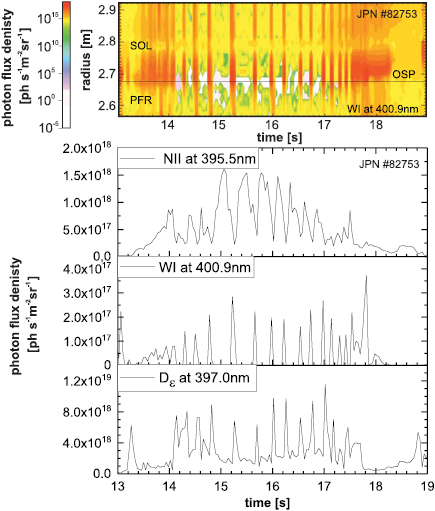
Figure 3. (a) Spatio-temporal evolution of W around the OSP in a N-seeded H-mode discharge in D with low  . (b) Corresponding temporal evolution of NII at
  nm, WI at
  nm, and the
  at
at  nm photon flux density at the OSP.
Download figure:
Standard image High-resolution imageHowever, during a short ELM burst with a duration of approximately  ms re-attachment occurs, thus, the fuel and impurity ions burn through the detached steady-state plasma reaching the target plate. These ions are much more energetic in comparison with the background divertor plasma ions and cause W sputtering as it is depicted in figure 3(b). The emission of WI in the intra-ELM phase is synchronous with the impinging deuterons and impurity, Be and N, ions, which are coming from hot plasma regions—namely the plasma pedestal as discussed further below. The NII excursions are inverted which can be attributed to two processes: (a) the photon efficiency for the NII transition is lower at the higher Te present during an ELM excursion, thus, a similar amount of particles produces less light emission. (b) the additional flux of impinging ions is vastly dominated by deuterons, thus, the local concentration of N ions during the intra-ELM phase is lower than during the inter-ELM phase. The composition of impurity ions hitting downstream the W target plate reflects to a certain extent the upstream conditions with e.g. the low concentrations of N and Be in the pedestal region in comparison with the high N concentrations in the divertor where the N is usually injected as N2 and recycled as N. Moderate reduction of the nitrogen seeding rate leads to re-attachment of the plasma in the inter-ELM phase and, as the radiative cooling by N is not sufficient, to impact energies of Be and N ions above the W sputtering threshold resulting in an increase of the total W source.
In the case of fully attached divertor conditions both phases, the intra- and the inter-ELM phase, contribute to the gross erosion of W and disentanglement of both is challenging in particular as in addition  is usually higher in JET plasmas. Figure 4(a) is describing the fraction of intra-ELM erosion to the total W erosion in the outer divertor in a set of unseeded D baseline H-mode plasmas in identical magnetic configuration with OSP on the bulk-W PFC. The data scatter is caused by the variation of the actual impinging ion flux distribution, the impact energies of ions, and the ELM frequency. The latter limits in general the spectroscopic analysis as the time resolution is often insufficient to separate the intra- and inter-ELM phases at high
  and averaged signals are used for analysis. However, den Harder et al could separate both contributions combining two spectroscopic systems with good spectral and temporal resolution [21]. In baseline H-mode plasmas up to 80% of the W gross sputtering occurs in the intra-ELM phase with the outer strike line positioned on the attached bulk W target plate. Note that the star in the figure relates to the conditions in the experiment (C30C) described below in section 3. Further statistical analysis of the experimental data [21] revealed a dependence of the gross W erosion yield on the power crossing the separatrix and the plasma pedestal temperature (
 ) (figure 4(b)) suggesting that the pedestal is the origin of the energetic ions hitting the target plate during the intra-ELM phase at highest input power. At a certain ELM frequency, the so-called ELM flushing of W from the pedestal region into the SOL sets in. Thus, though each ELM event is causing W erosion and release of W into the confined plasma, the W concentration in the core is not further rising under otherwise comparable impurity transport conditions, but W is expelled from the confined region during each collapse of the pedestal. This opens an operating window for W control with the ELM frequency. In type-I ELMy H-mode plasmas in JET, an ELM frequency of
  Hz is required to release more W from pedestal region than W is produced during an ELM impact in the set of analysed baseline plasmas [21].
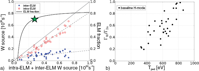
Figure 4. (a) Variation of the inter- and intra-ELM sputtering of W in baseline H-mode plasmas in JET equipped with ILW. (b) Increase of the effective W sputtering yield in unseeded JET H-mode plasmas as function of the pedestal temperature  . Reproduced courtesy of IAEA. Figure from [21]. Copyright (2016) IAEA.
Download figure:
Standard image High-resolution imageFurther insight on the intra-ELM sputtering source strength provides an analytical model introduced by Borodkina et al in [22] which is capable to describe the intra-ELM sputtering source as function of the pedestal temperature ( ), the impinging species composition, the impact angle, and the magnetic field including sheath effects. The impact energy of impinging ions is deduced from the free-streaming model of ions during the ELM collapse [23] which assumes that the electrons transfer most of their parallel energy to ions (
 ) to maintain quasi-neutrality. The resulting ions are almost monoenergetic with
  up to
up to  and therefore in the keV range as experimentally observed by [24]. The sputtering yields (figure 1) for W by different fusion-relevant ions starts to flatten above 2–3 keV and at even higher energies implantation of ions into W sets in as significant concurrent process. The erosion per ELM impact as function of
  is shown in figure 5(a) obtained from the analytical model and considering a pure D plasma, a magnetic field of
  T, and a pedestal density of
  as constant input parameters. With rise of
  , thus indirectly, with the projectile energy
  during the ELM collapse, a significant rise of the W erosion per ELM of e.g. factor two between
  eV and
  eV occurs which flattens at higher energies. The consideration of a small fraction of impurities in the pedestal region e.g. Be2+ with a concentration of
  Be2+ leads to an increase of the intra-ELM erosion of W up to
  with respect to the pure D case. The exchange of the hydrogen isotope ion in the model, as shown in figure 5(b), unveils a strong isotope dependence of the W erosion per ELM impact with twice as high erosion by tritons in comparison with deuterons at the same initial pedestal conditions. The fraction of Be ions was kept constant in this study whereas it might rise in addition during T plasma operation due to higher sputtering of Be from the main wall due to heavier charge-exchange neutrals [11].

Figure 5. (a) Variation of the contribution of Be ions to the intra-ELM W sputtering in D plasmas as function of  . (b) Variation of the intra-ELM W sputtering as function of
  for the three hydrogen isotopes calculated from the analytical model described in [22].
Download figure:
Standard image High-resolution imageIn the case of plasmas with impurity seeding also the seed impurity, e.g. N in the JET case discussed before, needs to be taken into account in the intra-ELM sputtering determination and its strength depends on its mass and concentration in the pedestal region. The seed impurity can thereby dominate over the hydrogenic ions and the ions of the main intrinsic impurity Be. Please note, that the experimental observations and their interpretation in D plasmas are consistent with recent studies in DIII-D [37] where the main impurity fraction—carbon in the percentage range—in the flux towards the target plate dominates the W sputtering in the intra-ELM phase over the impinging deuterons.
3. W erosion in quasi-steady-state plasma conditions
3.1. Experimental analysis
The critical question to address is: how can the in situ observed gross eroded W determined by OES be related to the net eroded W and where does the W deposition for a specific plasma take place? PMA provides the final distribution of net erosion and net deposition, however, in JET this is integrated over a typical campaign, which lasts about 20 plasma hours and therefore consists of a variety of different magnetic configurations and plasma conditions. General trends might be obtained by sorting along magnetic configurations [41] and exposition times, but it is challenging to connect this in general to a individual plasma conditions as the change of configurations is smearing the erosion/deposition pattern.
At the end of the first year of JET operation with ILW and just before extraction of a subset of divertor PFCs, a series of 151 identical D discharges in baseline H-mode with neutral beam heating [6] are carried out ( ,
,  T,
T,  MA) with static magnetic configuration (figure 6) over the whole divertor phase of the plasma. The series of identical, unseeded discharges, labelled as C30C in the following analysis, accumulated an exposition time of approximately 900 s in the H-mode phase with attached divertor conditions in the outer leg and semi-detached conditions at the inner leg. In total 2500 s of plasma were executed in divertor configuration of which 1600 s took place under ohmic conditions with both legs attached, but at low ion fluxes to the PFCs. The discharges were highly reproducible with a disruption probability rate of less than
  . Statistical analysis of all successful discharges provided the following averaged main plasma parameters in the H-mode phase: line averaged density
  , core electron temperature
  keV, total input power
  MW, radiated power
  MW, and a global radiated fraction
  . Further information about the temporal evolution of discharge parameters of a subsequent sequence of plasmas used for fuel retention studies are presented in [6].
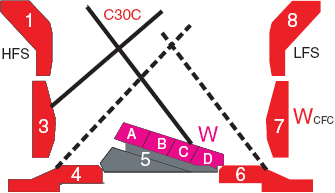
Figure 6. Magnetic configuration used in JET in the campaign C30C with vertical/semi-horizontal strike-line configuration on tiles 3/5 for ISP/OSP in comparison with so-called corner configuration with strike-lines in the pumping ducts on tiles 4/6 for ISP/OSP.
Download figure:
Standard image High-resolution imageThe deuterium plasmas had a high purity with  determined predominantly by Be with an approximate concentration of
  and residual C with a concentration of
  in the plasma. The corresponding temporal evolution of
  over the two weeks period of plasma execution is shown in figure 7(a). Figure 7(b) depicts the evolution of three characteristic impurity lines in the edge plasma of the main chamber: of Be (
 at
at  nm), C (CIII at
  nm), and O (
 at
at  nm). The levels are almost constant and in-line with the temporal behaviour of
  measurements though a slight reduction of C and a very moderate increase of Be can be seen with discharge number. This reflects a cleaning effect under the constant magnetic configuration in the divertor: the cycle of C erosion/deposition is interrupted and residual C is deposited at remote sides whereas Be is continuously produced by first wall erosion. The O level remains constant at a low level over the two weeks of the experiment execution suggesting a minor continuous source related to vessel vacuum conditions. Figure 7(c) displays for comparison the W radiation distribution in the confined region in the spectral range of soft x-ray [7] resulting in reconstructed W concentrations of
  in the main plasma. The plasmas show no accumulation of W though central heating by RF was not applied. It should be noted that no relevant contamination of the plasma by Inconel 625 components, namely Ni, Cr, Fe, from recessed vessel wall areas due to charge-exchange neutrals was recorded during the first year of ILW operation.
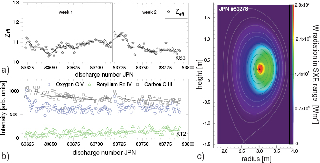
Figure 7. (a) Evolution of  averaged over the plateau phase of each H-mode discharge in C30C. (b) Corresponding evolution of intrinsic impurities
  in the main chamber. (c) Distribution of W radiation in the main confined plasma for a typical C30C plasma.
Download figure:
Standard image High-resolution imageThese H-mode discharges in pure D feature only a moderate confinement with an averaged pedestal density of  and a temperature of
  eV prior to the pedestal collapse resulting in clean type I ELMs with a repetition rate of
  Hz. In total about 30 000 ELMs occurred in the series of consecutive discharges which represents with
  a significant percentage of all ELM events in the first year of ILW operation—performed in all types of magnetic configurations. The inboard strike-line (ISP inter-ELM: Te = 7 eV and
  m−3) was positioned on the vertical target plate (tile 3) at a location used predominantly in the first year. The vertical target PFCs are made of 2D carbon-fibre composites with 20
  m thick W coating on the surface. Previous studies about the migration of Be in JET by OES and PMA confirmed that in the first year of operation, the inner divertor strike-line location was not deposited by Be, but remained essentially erosion zone with intact W surface [11]. The outboard strike-line (OSP inter-ELM conditions: Te = 35 eV and
  m−3) was positioned on the bulk-W divertor (tile 5, stack C) and the exposure at this position can be correlated to the period of plasma operation in C30C.
Figure 8(a) shows a representative heat load pattern at the outer target plate, measured by infrared thermography, averaged over the intra-ELM and the inter-ELM phase. The lamellae structure of the bulk W target plate as well as the shadowing with a global wetted fraction of about  in the applied magnetic shape in low triangularity is visible. Coherent ELM-averaging was applied to a subset of about 10 000 ELMs to derive the corresponding spatio-temporal evolution of the intra-ELM heat load pattern as depicted in figure 8(b). Comparison of the two footprints reveals a broadening of the intra-ELM power load footprint of about 1.8 in comparison with the averaged power load footprint largely determined by the inter-ELM phase.
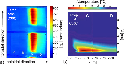
Figure 8. C30C: (a) Averaged surface temperature distribution determined by IR thermography at the outer strike-line. (b) Spatiotemporal evolution of the surface temperature during an ELM cycle deduced from coherent ELM averaging. The reduced observation area for temporally resolved ELM studies is marked by the black box depicted in part (a).
Download figure:
Standard image High-resolution image3.2. Optical emission spectroscopy: W gross erosion
Figure 9(a) shows for one representative discharge of C30C the spatio-temporal evolution of the WI photon flux density of the transition ( ) at
) at  nm measured in front of the bulk-W target plate. The spectroscopic system averages due to insufficient temporal resolution over inter-ELM and intra-ELM phases resulting in a interaction footprint comparable to the steady-state IR thermography pattern (figure 9(a)). This spatio-temporal footprint can be separated into four discrete phases: (i) The first phase is related to the formation of the x-point out of the limiter plasma and initialisation of the inner- and outer-strike line in the divertor. The limiter phase is characterised by high Be concentrations in the range of 3%–5% [38]. Diversion of the last-closed flux surface onto the divertor PFCs is expanding a high flux of energetic Be ions into the low density volume of the divertor. Consequently, a high local W sputtering by Be ions at the strike lines occurs for about 400 ms which can be seen in figure 9(a)—labelled as SL—causing typically a strong radiation peak owing to W. (ii) The second phase is the ohmic plasma used to rise the density by circumferential fuelling as well as to achieve stable conditions with overall low fluxes to the W target plates. Consequently, the W erosion is low as visualised in figure 9(a). (iii) The reference phase is the six seconds long H-mode plasma with the combination of intra- and inter-ELM W sputtering which predominantly determines the overall W erosion in the discharge. (iv) The last phase is the exit of the H-mode plasma which requires a careful reduction of the global radiation—also by W—with reduction of the auxiliary heating and simultaneous drop of the ion flux to the PFCs. This causes a flux of W from the main plasma towards the divertor and the risk of enhanced self sputtering of W on W. Though this phase can be critical in general, in the present case no limitations on operation or extensive W sputtering leading to a radiation collapse could be observed. The strike line was slightly shifted during the adjacent current ramp down period of 6 s duration. Therefore, we relate in the following the W gross erosion source predominately to phase (iii), but considering the ohmic phase (ii) in the budget over other low flux phases with the same fixed strike-line position. Phase (i) and (iv) are neglected in the analysis. The integrated gross W erosion at the outer target plate (bulk-W) during the H-mode phase (iii) was finally derived from the WI photon flux density depicted in figure 9(a) under consideration of the total exposition time, the total interacting surface area, and applying an averaged inverse photon efficiency of
 ![${[\frac{S}{XB}]_{\rm average}}=50$](https://content.cld.iop.org/journals/0029-5515/59/9/096035/revision2/nfab2aefieqn094.gif) according to local Te around the outer strike line. This averaged inverse photon efficiency considers on the hand the [
according to local Te around the outer strike line. This averaged inverse photon efficiency considers on the hand the [![$\frac{S}{XB}]_{\rm inter\mbox{-}ELM}$](https://content.cld.iop.org/journals/0029-5515/59/9/096035/revision2/nfab2aefieqn095.gif) -value of 45 for the inter-ELM phase and the [
-value of 45 for the inter-ELM phase and the [![$\frac{S}{XB}]_{intra-ELM}$](https://content.cld.iop.org/journals/0029-5515/59/9/096035/revision2/nfab2aefieqn096.gif) -value of 53 for the intra-ELM phase according to the multi-machine scaling [6]. On the other hand a
-value of 53 for the intra-ELM phase according to the multi-machine scaling [6]. On the other hand a  distribution for the
  -ELM-phases of gross W sputtering in-line with the measurements shown in figure 4(a) marked with '
 '. The overall gross erosion of W eroded from the outer target bulk-W PFC in this period of equal H-mode plasma was determined to
  g via OES considering the different uncertainties mentioned before.

Figure 9. (a) C30C: Temporal evolution of the spatial spectroscopic footprint of the WI photon flux density around the outer-strike line. (b) 2D distribution of WI emission at  nm in the JET divertor dominated by the intra-ELM phase (
 ms).
ms).
Download figure:
Standard image High-resolution imageSpectroscopic access to the inner divertor is in comparison with the outer divertor less prominent in JET. A mirror-based endoscope equipped with interference filtered 2D cameras provides spectral information in the whole divertor with low temporal resolution—typically averaging over the intra- and inter-ELM phase. Figure 10(a) shows the WI emission at  nm (filter: FWHM = 1.0 nm) and figure 10(b) the distribution of
  emission recorded simultaneously in both divertor legs. The data is averaged over the last two seconds of the H-mode plateau phase of the indicated JET discharge number. The divertor is in both legs in the ionising regime, thus, figure 10(b) shows the sputtering flux of W as discussed before and figure 10(b) describes essentially the recycling flux as representative for impinging deuteron flux. Continuum radiation at the inner divertor leg is polluting the line emission, but can not be further resolved here and the novel two-filter system presented in [39] was not in place at time of the experiment C30C, however, single frames of the intensified camera system can be dominated by the intra-ELM sputtering phase as shown e.g. in figure 9(b). Figures 10(c) and (d) show the corresponding tomographic reconstructions of WI and
  emission into one poloidal plane for the same averaging period, thus, multiple intra- and inter-ELM phases. The low electron temperature (Te = 7 eV) in the inner divertor leg would essentially correspond to an impact energy for the main important Be ions just at the sputtering threshold for the intra-ELM phase as marked in figure 2 by the '
 '. Nevertheless, strong WI emission is detectable which can only be attributed to intra-ELM sputtering of W which unfortunately was not temporally resolved by the detection system and is partially overlaid by continuum radiation.
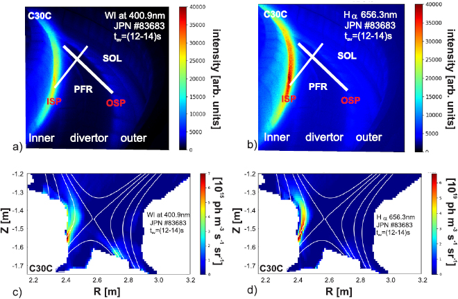
Figure 10. (a) C30C: (a) 2D distribution of WI emission at  nm in the JET divertor integrated over inter- and intra-ELM phases between t = 14 s and t = 16 s. (b) Corresponding 2D distribution of
  emission. (c) Tomographic reconstruction of WI emission into one poloidal plane. (d) Tomographic reconstruction of
  emission into one poloidal plane.
Download figure:
Standard image High-resolution imageA third multi-chord spectroscopic system, equipped with four-channel polychromators with narrow-band interference filters including standard WI, BeII,  transitions [21], was used which provides information with higher temporal resolution capable to resolve the inter- and intra-ELM phase for both divertor legs. However, the system integrates in 3 cm wide circular chords in the divertor and provides no spatial information at the inner target plate if the ISP is on the vertical target positioned. Coherent ELM-averaging technique was applied to the large number of ELMs [40] to study the W-related PSI in more detail. Figure 11(a) visualises spatially integrated in the inner divertor leg the statistical analysis of the BeII photon flux, representative for the impinging Be flux, the WI photon flux, representative for the W erosion flux, as well as the
  photon flux which reflects a combination of recycling flux prior to the ELM impact and recombination due to outgassing after the ELM impact [6]. The W sputtering in the inner leg is predominantly determined by the intra-ELM phase which can be clearly seen by the synchronous emission of the WI photon flux density with the BeII flux density as well as the ion flux density measured by Langmuir Probes. The WI emission prior and post the ELM excursion are very low as the inner leg is nearly semi-detachment in the intra-ELM phase and the ELMs and the associated deuterons and Be ions just burn through to the inner W target, made of W-coated CFC, as discussed in the previous section. The outer leg is in the described intra- and inter-ELM mixture, but due to malfunction of one photomultiplier detector of the polychromator system, no ELM-resolved W erosion at the spatial location of OSP is available in contrast to the analysis done in [21]. Figure 11(b) describes therefore the residual intra-ELM W flux density of the outer leg in the PFR and SOL excluding the one circular spot of d = 3 cm observing exactly at the OSP.
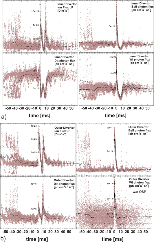
Figure 11. (a) ELM averaging at the inner divertor leg: impinging deuteron flux density (Langmuir probes), recycling flux density ( ), Be impurity flux (BeII at
  nm), gross W sputtering flux density (WI at
  nm). (b) Corresponding ELM averaging at the outer divertor leg [w/o OSP]. Reproduced from [44]. © IOP Publishing Ltd. CC BY 3.0.
Download figure:
Standard image High-resolution image3.3. Post-mortem analysis: W net erosion
PMA gives access to net material migration paths integrated over several hours of JET plasma operation including the local transport of W close to erosion source, the global transport of W towards the confined plasma, and finally transport to remote areas in the divertor and main chamber wall. The later represents an area where W cannot be re-eroded anymore as the impact energy of ions is below the threshold or geometrically screened. Though this material transport is integrated over all types of plasma conditions and magnetic configurations, PMA techniques such as e.g. Rutherford backscattering (RBS) and Nuclear Reaction Analysis (NRA) applied on standard PFCs are capable to provide information about global migration paths of W, Be, and, other impurities [41].
The combination of the well-established PFC marker layer technique [18] and the accumulation of a large plasma fluence in one magnetic shape before tile removal was applied to correlate the macroscopic W erosion/deposition pattern to as single plasma condition. A poloidal set of W PFCs was extracted directly after the execution of the previously discussed series of H-mode plasmas (C30C) including W-coated CFC PFCs and several W lamella of the bulk-W divertor (tile 5) at the OSP as marked in figure 12(a) and subsequently analysed by PMA. However, there was no standard W marker layer tile 3 from the vertical target with the pre-dominant exposure of the inner strike-line removed, but an unique tile with solely Mo finish at the surface which inhibits a correlation of the W sputtering to the last period of H-mode discussed here. However, strong Mo erosion of more than  m was recorded over the full first year of operation. The OES was thereby not observing the Mo, but a corresponding W tile toroidally away from the analysed PMA tile 3 with Mo finish. It shall be noted that PMA confirmed net W erosion at this spatial location place in the second year of operation with the ILW for a comparable integral period of plasma fluence and plasma conditions [42].
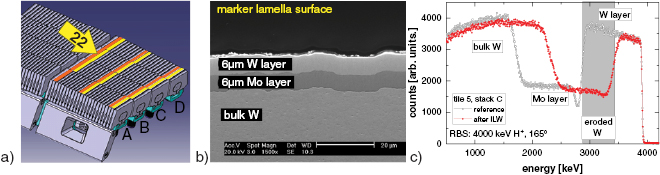
Figure 12. (a) Image of the bulk-W target plate with W/Mo/W marker lamellas in yellow. (b) Marker lamella cross-section with intact W/Mo/W layer prior to exposure. (c) Typical RBS spectrum prior and post plasma exposition of a single lamella (22) positioned at the OSP in C30C.
Download figure:
Standard image High-resolution imageFigure 12(b) depicts a typical marker layer consisting of a  m W layer on top of a
  m Mo layer deposited by combined magentron sputtering and ion impantation (CMSII) [43] on a W lamella prior to exposure in the tokamak plasma. Figure 12(c) shows typical RBS spectra taken with a proton beam at an impact energy of 4 MeV prior and post plasma exposure at one measurement point at the poloidal location of lamella 22 as labelled in figure 12(a). The grey marked area in the RBS spectra is proportional to the reduction of the top W layer thickness due to (net)erosion of W by plasma impact. The more detailed analysis discussed in [27] included a toroidal scan of 5 points over each of the slightly shaped W lamellae in toroidal direction and 6 points poloidal direction for each of the 11 lamellae analysed in total. The toroidal variation within each lamellae is very small (coloured squares in figure 13(a)) and taken in the following estimation of the total net W source as constant. Considering the global wetted fraction of the bulk W divertor modules in the given configuration discussed before, the lamella locations at the centre and the plasma-exposed left edge of stack 5C on one module shall not receive a significant difference in heat and particle load. But in detail there is variation in the W erosion resulting in an almost complete erosion of the top W layer of
  m in the centre lamella (figure 12(a)) at the strike-line location used in the C30C experiment, as described in [27], and about half (
 3
3  m) of it at the edge lamella 22 shown in figure 13(a). The corresponding profile of Mo is completely in-tact, thus no W erosion down to the Mo layer took place like observe on stack 5D. The difference in the lamella erosion is most likely attributed to the installation precision of the individual lamella. The W lamellae (right in figure 12(a)) in the shadowed area due to the wetted surface fraction shows no significant W erosion as expected. Note that the surface roughness (figure 12(a)) is in the order of
  m, thus, slightly smoother than the initial roughness during manufacturing. Thus, in the following for the W net erosion we assume the plasma surface coverage according to the particle and heat load footprint discussed before and identical with the one used in the spectroscopic determination of the W gross erosion. At least half of the net W erosion can be related to the 900 s H-mode phase in C30C and the residual erosion is attributed to comparable other H-mode plasmas and L-mode phases which have been summed up over the complete first year of operation at this location. Comparison of the W source spectroscopy in the intra- and inter-ELM phases with the post-mortem analysis provides therefore one pair of gross and net W erosion: OES determines the W gross erosion to
  g and PMA the W net erosion to 2.4–3.6 g over the 900 s considering the interaction area in the circumference of the outer divertor and the uncertainties of the net erosion pattern homogeneity. This corresponds to a high re-deposition fraction of more than
  averaged over both phases of the H-mode. It should be noted that the smoothing of the W surface roughness of the lamellae post plasma exposition can be interpreted as a results of the high re-deposition, thus, higher capturing probability of eroded W due to the local geometry in the micrometer scale.
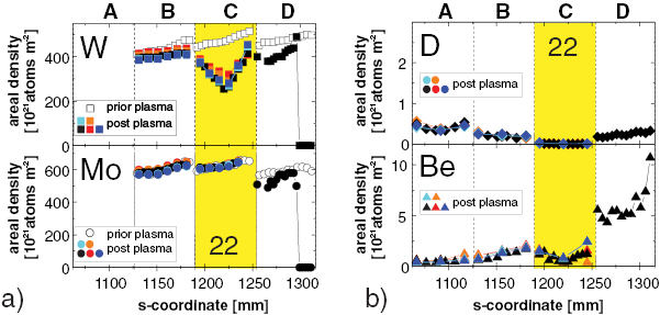
Figure 13. Spatial distribution of areal densities in poloidal direction determined by RBS at marker lamellae along the bulk-W target plate. (a) Erosion of the top W layer and in-tact Mo inter layer with the lamella at the OSP marked in yellow. Multiple measurements at one poloidal position are done in toroidal direction indicating homogenous erosion distribution in this direction. (b) Corresponding D and Be content in the lamellae surfaces after plasma exposure in C30C.
Download figure:
Standard image High-resolution imageFigure 13(b) depicts the corresponding distribution of Be and D on top of tile 5, measured by NRA with 3He at 2.5 MeV. The distribution of Be along the target plate confirms, that there is no Be layer deposited at the location of the strike-line as suggested from the W and Mo profiles. The impinging Be ion flux, which is partially responsible for the W sputtering as described in the previous section, is insufficient to shift the OSP into a deposition dominated area. The residence time of Be ions on the W surface is too short as impinging D+ can easily sputter potential Be atoms sticking on the top W surface as well as the reflection coefficient of Be on W is very high for the given impact energies in the experiment. The situation is different further in the scrape-off layer on the neighboured stack of tile 5. In the experimental conditions of the C30C case with static strike-lines during the H-mode phase, this poloidal location showing a five times higher Be surface concentration indicating partial surface coverage of W by Be and the potential build up of a thin Be layer on top of the W lamella stack 5D. The impact energy and amount of D+ at this location seems no longer sufficient to re-erode the Be from the top surface. The local flux of Be ions on stack 5D might be enhanced due to Be eroded from stack C and transported from stack 5C to 5D as observed before for carbon ions (13C) in previous JET experiments with graphite divertor and labeled as walking process [45]. However, all these processes cannot explain the step-like increase of the Be concentration along the target plate in from 5C to 5D which indicates the need for an additional cause. Here, one must consider the potential difference in surface temperature of the thermally isolated bulk W stacks discussed before. The IR thermography reveals peak steady-state surface temperatures on stack 5C of around 1400 °C at the end of the 6 s long plateau phase of the H-mode discharge. This temperature is sufficient high to evaporate residual Be atoms from the top lamella W surface which can explain the step-wise rise of Be between stack 5C and 5D, and potentially also the Be step from 5C to 5B towards the PFR, as the evaporation is significant at temperatures above 950 °C, thus, expands into the post-plasmas phase.
The significance of the high surface and bulk temperature at the end of operation before tile removal is also clearly visible in the measured D content which is extremely low at the location of the outer-strike line (figure 13(b)). The high temperature of the uncooled W PFCs up to the mentioned 1400 °C corresponds to a low fuel concentration in the bulk-W divertor and each W lamella by deuterium implantation as co-deposition is not present at this location. The long waiting time of typically 35-45 minutes between two JET discharges leads consequently to further outgassing of fuel from these W PFCs. Additionally, the short ELM impact in the H-mode phase induced on top a rise of surface temperature of about 100 °C as described before in figure 8(b) which further emptied the reservoir of fuel a this plasma-material interaction location with the W PFC. Further information about the deuterium recycling behaviour in these conditions and its impact on the plasma fuelling can be found in [44].
The formation of WD molecules due to CAPS—observed before at much lower surface temperature in ASDEX Upgrade and TEXTOR—is most likely prevented at this elevated temperatures due to lack of deuterium embedded in the near W surface and can in the first order approximation be neglected as strong erosion path at the strike-line for these discharges. However, it might still contribute to the erosion of W at locations further away of the near-SOL, thus, in this configuration closer to the corner region, in particular on the in-tact W surfaces on tile 5 stack 5D and on tile 6.
3.4. ERO modelling: W gross and net erosion
The 3D plasma-material interaction and transport code ERO [12, 25] was applied to model the complex local erosion and re-deposition cycle of W in the quasi-steady-state H-mode plasma experiment C30C. The aim of this ERO code application is to further verify the underlying physics processes related to W erosion, transport, and deposition under the high magnetic field conditions in tokamaks, and to compare for the first time quantitatively the gross erosion of W, measured by OES, with the net erosion of W, derived from PMA, in a JET experiment. The code is—with appropriate plasma background conditions for divertor and pedestal region—capable to disentangle the intra- and inter-ELM contributions to the observed gross and net erosion of W as well as to describe the erosion and deposition pattern along the target plates. This unique benchmark experiment paths the way to predictive modelling of W erosion and deposition in future JET DT plasmas with ILW.
The studies presented here were carried out with the non-parallelised version ERO 1.0 with restrictions in the simulation volume permitting to model one toroidal section of one divertor leg. Therefore, inner and outer divertor were treated in two independent simulations by applying the local geometries, the magnetic field configurations, the local plasma parameters, the impurity influx compositions as well as the pedestal conditions as separate input parameters to each leg. These local divertor studies are not fully self-consistent in respect to the Be ion flux entering the divertor and inducing W sputtering as the global migration of Be in the tokamak with Be eroded at the main chamber and transported into both divertor legs is not covered. Instead experimentally derived concentrations of Be ions are applied and related to the impinging deuteron flux to the target plates to describe the impinging impurity ion flux. Though the modelling is performed under the principle assumption of toroidal symmetry in the JET divertor, the global wetted fraction of the PFCs for the used magnetic field configuration were applied to compare it with OES and PMA analysis discussed before. The surface roughness of W PFCs has been neglected in the modelling assuming a smooth top W surfaces already at the start of the simulations and no difference between bulk-W tiles in the outer and W-coated components in the inner divertor. Finally, W eroded and redeposited at the tile surface is treated as bulk W material again, thus, we assume no difference in the erosion yields or binding energies of initially present W and deposited W. Note, that the currently developed fully parallelised ERO version 2.0 [47] will be applied in future for a full consistent material migration modelling in the complete JET tokamak geometry with Be first wall and W divertor including the option to consider different surface roughnesses for the inner and outer divertor target plates [48].
A first benchmark of the ERO code was performed in [46] by comparing experimental and modelled W gross erosion fluxes in the JET outer divertor leg in a comparable magnetic configuration to C30C (6). Though the input power was similar to C30C values, slightly different plasma fuelling lead to distinct local plasma conditions in both divertor legs during the inter- and intra-ELM phase of the H-mode discharge. However, this ERO modelling of W gross erosion in inter- and intra-ELM phases [46] was in good agreement with the experimentally deduced one determined by OES observing the reference WI transition ( ) at
) at  nm. The ERO modelling of C30C plasmas represents therefore the next step of these studies with adaption of the experimental plasma conditions in the divertor and the pedestal, but expansion of the modelling to both divertor legs as well as to the net erosion and redeposition fluxes of W in a single experiment which is unique for JET in the absence of any manipulator system usable for sample exposition and therefore access to experimentally resolved PMA data.
3.4.1. Outer divertor leg.
Figure 14 shows the main results of ERO calculations for the inter-ELM phase of C30C plasmas at the outer divertor leg with the peak plasma parameter Te = 35 eV and  at the strike line. The Be concentration in the ion flux to the outer target plate is in this simulation fixed to
  in the form of Be2+ ions. Apart from Be no other intrinsic impurities (i.e. C, O) are considered here which is in full agreement with the global analysis of impurity composition in C30C done at the start of this section. Self-sputtering of W by initially eroded W atoms, returning to the surface as W ions with high enough energy to induce sputtering of another W atom is included in the simulations, too. The self sputtering yield of W ions on W atoms is very high due to the equality of mass of projectile and target. Note that there is no experimental access in JET to isolate and quantify this process from other sputtering events for a comparison of experiment and modelling. Finally, sputtering of W surfaces by W ions which enter the divertor from the confined main plasma like present e.g. in ASDEX Upgrade is not covered in the local model; main chamber W PFCs in JET are negligible.
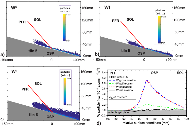
Figure 14. ERO modelling of inter-ELM erosion at the outer target plate: (a) Spatial distribution of neutral W sputtered at the bulk W PFC. (b) Spatial distribution of corresponding WI emission at  nm. (c) Spatial distribution of singly ionised W. (d) Inter-ELM erosion and deposition fluxes as function of radial position at the outer target plate. The small residual net erosion flux of W is marked.
Download figure:
Standard image High-resolution imageFigure 14(a) depicts the distribution of gross eroded W atoms, denoted in the following as W0, sputtered at the bulk W divertor by the impinging ions. The erosion takes place in a very narrow area around the outer strike-line (OSP) in the near-SOL. The penetration depth of atoms is in general in the millimeter range in the near-SOL and slightly higher for a small fraction of W atoms moving into the cold private flux region (PFR). The corresponding distribution of WI light emission of the transition at  nm is shown in figure 14(b) considering atomic data from GKU for the electron impact excitation [49]. The light pattern essentially follows largely the W atom distribution with the strongest light emission at the strike line and residual low emission extending further into the SOL. Figure 14(c) shows the spatial distribution of singly ionised W, labelled as W+ , with the characteristic large Larmor radius visible for the odd escaping ion into the PFR. The vast majority of W+ is distributed similar to W0, thus located directly in front of the bulk W target plate around the strike line. Also here a small fraction of ions is escaping the modelling volume poloidally towards the SOL (0.5%), or more precise, towards the corner region of the outer JET divertor. The local balance of W erosion and deposition in the inter-ELM phase along the bulk W target is visualised in figure 14(d) by the W gross erosion, W deposition, and the resulting W net erosion flux densities versus the relative surface coordinate with the origin fixed at the OSP. The poloidal distribution of the W gross erosion flux follows mainly the impinging ion flux distribution, or better, the Be ion flux distribution which determines the W sputtering, owing to the fact that all the impinging Be ions in the near-SOL of the outer divertor have impact energies above the W sputtering threshold. The significant fraction of W gross erosion flux due to the W self sputtering (∼20%) is shown in the figure, too. The W self sputtering flux considers not only singly ionised W+ impinging onto the surface again, but also higher ionisations stages in the divertor which potentially return to the target surface and are screened from the main plasma by the divertor. Note that the significance of this process has also been observed in simulations performed for the DIII-D metallic ring experiment [50].
But by far the most important outcome of the simulations is the comparable magnitude and distribution of the W gross erosion flux and the W redeposition flux. The difference between the two curves represents the low net W erosion flux distributed along the outer divertor target plate (figure 14(d)). Three zones can be identified: (i) Maximum net erosion of W at the OSP where the maximum ion flux with particles and energy well above the sputtering threshold hits the target plate. (ii) Maximum net deposition of W, marked as negative W net erosion flux, in the PFR next to the OSP where there is a residual particle flux, but the energy of the impinging ions is too low to erode W from the target plate. (iii) The first couple of centimeters in the SOL where erosion and deposition is almost balanced. Overall, the vast majority of gross eroded W at the target plate is redeposited at the outer target plate again and the corresponding re-deposition factor in the simulations for this case is about  . Thus, the small residual fraction of W can either pollute the plasma or is re-deposited outside of the modelling volume in the corner region. Though the outer divertor arrangement is geometrically characterised as open divertor arrangement, the screening of W in the divertor is extremely high due to the high re-deposition fraction under these intra-ELM conditions in the outer leg. This high re-deposition fraction in the case of inter-ELM W sputtering in unseeded H-mode plasmas in the JET ILW operational space of the first year is robust against reasonable, but moderate variations in the concentration of Be ions in the impinging deuteron flux. Neither an increase in the Be2+ concentration
  from
from  to
to  Be2+ , nor a change of the ionisation stage of the impinging Be from Be2+ to Be3+ at a constant concentration of
  change significantly the re-deposition factor for W though a moderate change in the absolute values of gross and net erosion are obtained in the modelling. Note that it is expected that higher Be ion concentrations in the impinging ion flux would change the erosion and deposition balances and turn the outer divertor from a net W erosion zone into a Be co-deposition zone, but this has not been observed experimentally on the bulk W divertor PFCs.
The corresponding figure 15 summarises the main results of ERO calculations for the intra-ELM phase of C30C plasmas at the outer divertor leg. The ELM impact is simulated, as discussed in section 2 by a monoenergetic impact of hot ions from the pedestal region of the plasmas with impact energies  keV. The ELM frequency in these plasmas is
  Hz and the sputtered W atoms by ELM impact are excited by electrons of the thermal background plasma, thus the inter-ELM plasma conditions presented before. The interaction time of ELM-induced particles with the target plate has been related to the fast rise of the surface temperature in the IR thermography of about 0.5 ms (figure 8(a)) which is connected to the collapse of the H-mode pedestal and subsequent outflow of particles from the pedestal into the divertor region. However, the thermal footprint of particles, ions and electrons, hitting the target plate during an ELM event extend to about 2.0 ms considering the classical power decay character [51]. An increase of the interaction time to 2.0 ms would enhance the intra-ELM induced sputtering values linearly by a factor four. The ion flux in the modelling hitting the target plate is in the intra-ELM phase like in the inter-ELM phase composed by
  deuterons and
  Be ions in the idealised form of solely Be2+ . The process of self sputtering is included in the simulations.
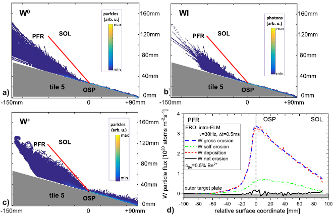
Figure 15. ERO modelling of intra-ELM erosion at the outer target plate. (a) Spatial distribution of neutral W sputtered at the bulk W PFC. (b) Spatial distribution of corresponding WI emission at  nm. (c) Spatial distribution of singly ionised W. (d) Intra-ELM erosion and deposition fluxes as function of radial position at the outer target plate. The small residual net erosion flux of W induced by ELMs is marked.
Download figure:
Standard image High-resolution imageFigure 15(a) depicts the intra-ELM distribution of gross eroded W atoms W0 sputtered at the bulk W divertor by the impinging fast deuterons and Be ions during an ELM event. The erosion takes place around the OSP and mostly in the near-SOL with an increase of particles escaping either into the PFR or SOL region. The main interaction area is slightly wider in the intra-ELM case in the comparison with the inter-ELM one whereas the penetration depth of atoms is even shorter. The light distribution of WI at  nm is given in figure 15(b) and it shall be stressed that the electron impact excitation of W atoms is determined by collisions within the background plasma with the peak electron temperature of Te = 35 eV at the OSP. The W particle distribution and the WI light emission are selfsimiliar with main appearance close to the target plate and expansion of the emission cloud into the SOL region. Figure 15(c) reflects the spatial distribution of W+ with the odd traces of full W ion gyration visible inside the PFR due to escaping ions. Contrary, at the OSP and in the SOL, largely local redeposition takes place with a moderate ion fraction of
  ions escaping the modelling volume towards the corner region. The local balance of W erosion and deposition in the intra-ELM phase along the target plate and integrated over 1 s plasma time, thus including 30 ELM events, is shown in figure 15(d). Similar to the inter-ELM case, the vast majority of gross sputtered W atoms returns promptly back to the target plate which is visualised by the comparable spatial distribution and magnitude of W gross erosion flux and W deposition flux along the the target plate. The overall net erosion in the intra-ELM phase is slightly higher than in the inter-ELM phase, nevertheless, the redeposition factor is still very high and above
  . Thus screening of W atoms induced by ELM impact is comparable with screening of eroded W atoms during the steady-state phase. Both ionic species, D and Be, contribute to the overall W sputtering during an ELM, but D+ dominates in the C30C case with a fraction of about
  of the overall net W sputtering flux. Further increase of the Be fraction in the impinging flux would lead to a significant rise of the fraction of impurity-induced sputtering during the ELM event as it is e.g. seen in DIII-D. In DIII-D equipped with graphite first wall and W divertor samples, the carbon fraction is in the impinging ion flux to the target in the percent range; impurities dominate the intra-ELM sputtering of W as measured and modelled with ERO [52].
The final step which is required in the ERO modelling in order to simulate the experimental observations of W erosion in C30C H-mode plasmas is the superposition of the corresponding intra- and inter-ELM results. Figure 16 shows as function of the relative surface coordinate the superimposed, or more precisely, added-up W erosion fluxes in the outer leg considering inter-ELM erosion (figure 14(d)) and thirty intra-ELM events (figure 15(d)) within one second. The ratio of intra-ELM and inter-ELM W gross erosion amounts to 75:25 and is close to the experimental ratio obtained from OES. The added-up gross erosion flux and deposition flux are—as expected from the individual contributions—similar in magnitude and in shape resulting in a very low net erosion flux of W with a re-deposition fraction of  which is slightly above the experimentally determined value of
  . The main fraction of escaping W from the re-deposition is in the modelling in direction of the SOL, or in JET geometry, into the outer corner region. The good screening of W in this open divertor configuration in ionising plasma conditions with intra- and inter-ELM contributions to the sputtering in H-mode is prevailed.
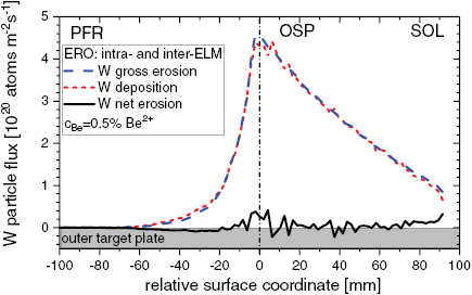
Figure 16. ERO modelling of gross erosion, deposition, and net erosion fluxes of W at the outer target plate integrated over intra- and inter-ELM phases of a C30C H-mode plasmas.
Download figure:
Standard image High-resolution imageTo summarise the outer divertor case: ERO can reproduce in general well the large integral gross erosion of W, the low integral net erosion of W, and therefore the high re-deposition of W on the bulk W divertor observed experimentally by optical emission spectroscopy and post-mortem analysis in the H-mode plasmas of the quasi-steady-state campaign C30C. ERO confirms further that both phases in this baseline H-mode plasma, the intra-ELM and the inter-ELM phase, contribute significantly to the gross and net erosion of W under these ionising divertor conditions which are present in the attached outer divertor leg. The intra-ELM phase dominates in the present case where the intra-ELM sputtering by deuterons is negligible. However, the ERO modelling with the input parameters overestimates slightly the degree of the W redeposition ( ) which as consequence is leading to a slightly higher net erosion of W at the PFC or equivalent to a higher flux of W entering the scrape-off layer and, potentially, the confined region. Nevertheless extrapolations to more challenging plasma conditions expected in JET DT are legitim, though the cause for the minor deviation will be further investigated on both sides—experiment and modelling. The latter will include in particular newer data for ionisation and emission rate coefficients from ADAS [53], an improved material mixing model for the top surface as well as dynamic modelling runs with subsequent inter-ELM and intra-ELM phases reassembling the 6 s H-mode flattop phase of a discharge with about 180 ELMs.
3.4.2. Inner divertor leg.
The same version of ERO used before to model the attached outer divertor conditions has been applied to the semi-detached inner divertor in order to derive the gross erosion and net erosion flux of W as well as its distribution along the vertical target for the H-mode plasma performed in the C30C experiment. The local experimental conditions, thus, the inner divertor geometry, the magnetic field line configuration, and the plasma conditions with Te = 7 eV and  at the inner strike line (ISP) were adopted in the modelling. Moreover, the flows in the scrape-off layer in JET in the applied magnetic configurations are inducing a preferred migration of Be from the main chamber into the inner divertor leg as described in [54]. The Be impurity flux from the main chamber into the divertor is therefore higher in the inner than in the outer divertor. The Be concentrations applied in the ERO modelling of the inner divertor leg is
  related to flux of D+ and predominantly in form of Be2+ for both phases, the inter and the intra-ELM one. Be is assumed to be the only intrinsic impurity.
Figure 17 shows the main results of ERO simulations for the inter-ELM phase of C30C plasmas in the inner divertor leg with the ISP positioned on the vertical target plate (tile 3). Figure 17(a) depicts the distribution of gross eroded W atoms sputtered at the W-coated CFC target plate by the impinging ions. The erosion takes place around the position of the inner strike-line ISP expands a few centimeters upwards in the near-SOL region. The penetration depth of W0 is on the flat part of tile 3 very short and lays in the millimeter range. It is slightly larger in the near-SOL which expands to the tilted upper part of tile 3. An almost negligible small fraction of W atoms is sputtered vertically below the ISP and W atoms are released towards the horizontal tile 4 located in the PFR. The associated WI line ( nm) emission pattern shown in figure 17(b) follows essentially the distribution of W0 with the main radiation zone in front of the flat as well as the upper tilted W surface of tile 3.
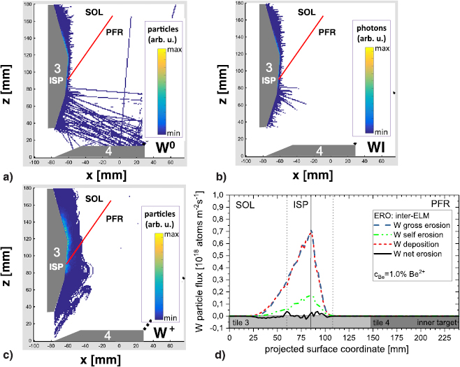
Figure 17. ERO modelling of inter-ELM erosion at the inner vertical target plate: (a) Spatial distribution of neutral W sputtered at the W PFC. (b) Spatial distribution of corresponding WI emission at  nm. (c) Spatial distribution of singly ionised W. (d) Inter-ELM erosion and deposition fluxes as function of radial position at the inner target plate.
Download figure:
Standard image High-resolution imageThe spatial distribution of singly ionised W in the inner divertor leg is described in figure 17(c). The penetration depth of W+ is clearly larger than the corresponding W0 penetration due to the higher magnetic field and the colder plasma with respect to the outer divertor where both depths were similar. The vast majority of W+ is distributed directly in front of the vertical target plate around the strike line location alike the W0 distribution. The re-deposition is almost perfect with  , thus, almost no eroded W atom is escaping from the inner vertical target plate in the inter-ELM phase. The erosion and deposition balance along the vertical target (tile 3) in the inter-ELM phase is visualised in figure 17(d). The W gross erosion, the W deposition, and the very small W net erosion flux densities are shown as function of the projected surface coordinate with the origin at the top of tile 3. Main net erosion of W appears as expected at the ISP, but also at the transition from the flat to the tilted tile surface in the SOL whereas net deposition occurs deeper in the near-SOL. The most important difference in comparison to the inter-ELM simulation in the outer lege is the total magnitude of W gross erosion and W deposition flux which is two orders of magnitude lower. This is due to the fact, that the impact energy of Be ions is just around the energetic sputtering threshold for Be projectiles hitting a W target. Thus, the cold inner divertor conditions in JET prevent W erosion in the inter-ELM phase of the C30C H-mode which confirms the advantage of this divertor regime in view of W PFC lifetime and W source strength. Complementary ERO simulations with an impinging Be2+ fraction of
  with respect to the D+ flux—as applied in the outer divertor—show no significant difference in the erosion and deposition behaviour.
Figure 18(a) depicts the spatial distribution of W gross erosion at the inner vertical target in the intra-ELM phase caused by impinging energetic deuterons and Be ions. W erosion occurs predominantly around the inner strike-line location, but erosion takes also place in the near-SOL, in z direction towards the main chamber, and in the PFR of the vertical target, too. This underlines the wider interaction area of impinging ions in the intra-ELM phase. Indeed the gross erosion zone of W extends into the near-SOL and beyond the boundary of the present ERO modelling towards tile 1 (see figure 6) in z-direction. Moreover, a small fraction of already eroded W particles from tile 3 escapes the simulation volume in the inner divertor leg in this direction towards the main chamber plasma. A second, much smaller fraction of W atoms is entering the PFR without further electron collision where reflection of W atoms on the horizontal W target (tile 4) can occur. The magnitude of intra-ELM erosion is more than two orders of magnitude higher than the inter-ELM erosion under the present inner divertor conditions.
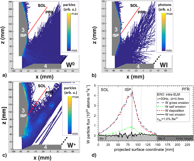
Figure 18. ERO modelling of intra-ELM erosion at the inner target plate. (a) Spatial distribution of neutral W sputtered at the W-coated PFC. (b) Spatial distribution of corresponding WI emission at  nm. (c) Spatial distribution of W+ . (d) Intra-ELM erosion and deposition fluxes as function of radial position at the inner target plate.
Download figure:
Standard image High-resolution imageThe spatial distribution of the corresponding WI line emission, determined by electron impact excitation of eroded W atoms, in the cold inner divertor background plasma (ISP: Te = 7. eV and  ) is given in figure 18(b). The W0 particle and the WI light distribution pattern are alike with main appearance close to the ISP and expansion into the near-SOL region at the vertical target plate as well as short penetration depth of particles and photons from the W surface into the plasma. The WI emission pattern is comparable to experimental observations with interference filtered (
 nm) camera systems indicated before in figure 9(b). Figure 18(c) shows the distribution of singly ionised W in the inner divertor leg with the predominant appearance around the ISP and in the near-SOL with sightly higher penetration depth of W+ into the divertor plasma in comparison with W0. The local balance of W erosion and deposition in the intra-ELM phase along the inner vertical target plate and integrated over 1 s plasma time, thus including 30 ELM events, is shown in figure 18(d). The vast majority of sputtered W atoms returns promptly back to the target plate; the spatial distribution and absolute strength of W gross erosion flux and W deposition flux is comparable. The re-deposition factor, which is in the ERO modelling related to deposition on the complete tile 3, amounts to
  , thus, much less re-deposition than in the inter-ELM case of the inner divertor takes place as well as much less re-deposition occurs than in the outer divertor.
It remains the question, where does the eroded, but non-redeposited W end up? A fraction of approximately  W atoms leaves the modelling volume into the near-SOL and in direction of the main chamber where pollution of the confined plasma can occur. About
  of W particles escapes the modelling volume into the inner divertor corner region, located in the PFR, where they cannot be eroded again within this magnetic configuration. Finally, a fraction of
  of W atoms enters the PFR in direction of the outer divertor. Indeed a second WI emission zone in the PFR away from the target plates is observable in the ERO modelling depicted in figure 18(b). W atoms eroded on tile 3 figure 18(a) are transported collisionless to horizontal tile 4 where they are reflected into the PFR. These reflected W particles will be ionised within the PFR when they are closer to the separatrix (higher Te) as described in figure 15(c). The exact transport path of this very small fraction of W particles is strongly depending on the plasma conditions present in the PFR. A single ERO simulation covering the full divertor geometry might be needed to answer the fate of these W particles.
The final step which is required to describe the inner divertor W sputtering with the ERO code is the superposition of the corresponding intra- and inter-ELM results. It is obvious that the added-up flux contributions to the W erosion will reassemble completely the intra-ELM case as the fluxes in this case are about two orders of magnitude higher than the inter-ELM fluxes. Figure 19 shows, as function of the projected surface coordinate, the superimposed W erosion fluxes in the inner leg considering inter-ELM erosion (figure 17(d)) and thirty intra-ELM events (figure 18(d)) within one second. The ratio of intra-ELM and inter-ELM W gross erosion amounts to 99:01. The added-up gross erosion flux and deposition flux are—as expected from the individual contributions—similar in magnitude and in shape resulting in a low net erosion flux of W with a high re-deposition fraction of  . The paths of W particles which escape the process cycle of re-deposition on the vertical target has been described in the intra-ELM case discussion. A reduction of the
  in the impinging ion flux to the target in (complementary) ERO modelling increases
  to
to  . This increase by
  is caused by a reduction of W particle losses towards the SOL.
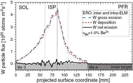
Figure 19. ERO modelling of gross erosion, deposition, and net erosion fluxes of W at the outer target plate integrated over intra- and inter-ELM phases of a C30C H-mode plasmas.
Download figure:
Standard image High-resolution imageTo summarise the inner divertor case: ERO can reproduce in general the large integral gross erosion of W on the vertical target observed experimentally by optical emission spectroscopy in the H-mode plasmas of the quasi-steady-state campaign C30C. ERO confirms further that under the cold, but still ionising divertor plasma conditions in the inner leg, the intra-ELM phase dominates the the gross and net erosion of W. Both Be ions and deuterons contribute comparable to the intra-ELM erosion owing to the higher concentration of Be in the impinging ion flux. The inter-ELM phase is a negligible contributor to W erosion owing to the low impact energy of impinging Be ions close to the energy threshold. ERO predicts further low integral net erosion of W, and therefore the high re-deposition of W in the H-mode plasmas of C30C. This is in general in-line with campaign-integrated post-mortem analysis which confirm low net erosion of the W-coated CFC tiles, but in the absence of C30C-resolved information, no quantitative comparison is possible. ERO predicts a fraction of about  of net eroded W particles escaping the (prompt) re-deposition cycle with potential to escape the divertor and it screening properties. The screening of W in the close divertor configuration present in the inner divertor leg seems less efficient than in the outer one discussed before. Both the magnetic configuration and the plasma conditions are responsible for this unexpected behaviour. Nevertheless extrapolations to more challenging plasma conditions expected in JET DT with e.g. Ne seeding to cool down the inner divertor target plate are legitim, though the situation with additional seeding species is more challenging. Adding Ne seed gas for radiative cooling will certainly increase the intra-ELM induced erosion due to Be and Ne ions present in the pedestal region. Movement of the inner-strike line down on the vertical target in direction of the inner corner will enhance the probability to re-deposit eroded W and increase the re-deposition fraction.
3.5. Comparison of inner and outer divertor W sources
The overall divertor screening in the divertor geometry and magnetic configuration used in the JET C30C H-mode plasmas reduces the W source by about two orders of magnitude and is largely determined by the (prompt) re-deposition of eroded W on the very same divertor PFC where the gross erosion of W took place. The residual W particles which escapes the re-deposition cycle can either enter and pollute the confined plasma or can be deposited in recessed areas like e.g. pump ducts (corner) and the PFR. The necessary conditions for further W sputtering from these recessed areas with respect to impinging ion flux and impact energy are not fulfilled in the given constant magnetic configuration and applied plasma conditions. Both divertor legs contribute to the overall influx of W from the divertor to the confined plasma region which results in the case of JET C30C H-mode plasmas in a tolerable core concentration of  . The sum of inter- and intra-ELM induced gross erosion of W is in both divertor legs comparable in absolute numbers, however, in the inner leg only the intra-ELM phase contributes to W erosion whereas in the outer leg inter- and intra-ELM phases are contributing. This is due to the local plasma conditions, the local geometric arrangement, and the applied local magnetic field configuration. Overall, the intra-ELM phase is the main driver for W erosion in the divertor with responsibility for more than
  of the total W erosion in C30C plasmas. Main projectile contributor to the intra-ELM W sputtering at both target plates are deuterons as the applied Be ion concentrations in the impinging fluxes are low in the experiment. Usage of the so-called corner configuration (figure 6), with both strike-lines in the pump duct areas, seems preferable from the point of W screening as residual W atoms escaping the (prompt) re-deposition cycle are geometrically better screened and escaping W is transported deeper into the divertor pump ducts and not into the confined plasma volume. Note that W deposition was found in the recessed areas of the pump duct which have no direct lines-of-sight to the plasma [41], but could have e.g. undergo reflection on recessed surfaces.
4. Conclusion
The interplay of gross erosion, deposition, and net erosion of tungsten at the divertor PFCs in JET has been studied in H-mode plasma conditions separating the impact of inter-ELM erosion of W, thus between ELM events, and intra-ELM erosion of W, thus during ELM impact. Analysis of the W gross and net erosion in these JET deuterium plasmas at the outer divertor by means of OES and PMA after the quasi-steady-state plasma campaign C30C revealed a large W re-deposition factor of more than  . Such high re-deposition factors for W can largely be reproduced or exceeded by ERO code simulations for the given experimental conditions in the outer divertor. ERO simulations predict similar values for the inner divertor though a larger fraction of W particles is escaping the W redeposition cycle. The W erosion in these H-mode plasmas is driven by intra-ELM sputtering of W with deuterons as dominant projectile species whereas inter-ELM sputtering by Be ions is either almost absence (inner divertor) or low as
  (outer divertor) for the given Be concentrations of less than
  in C30C plasmas.
4.1. Conclusions drawn for JET operating with tritium
From the experimental results presented in this paper and their interpretation with the ERO code, we can extrapolate towards the expected W erosion behaviour in JET plasmas with T applied as fuel species, thus, to TT or DT plasma operation [55] and give an advice concerning options to minimise the W source. Plasma operation with T as main fuel species will in general increase the gross erosion of W in the divertor due to (a) the mass dependence of the erosion yield, thus, increase of the projectile mass by  from D to T ions impinging on W, and (b) shift of the impact energy threshold to lower values due its mass dependence. The ELMy H-mode scenarios presently proposed for JET ILW plasmas in TT and DT are planned to operate with attached and ionising divertor in the outer and potentially also in the inner leg. The integrity of the passively cooled PFCs concerning power load limitations must be ensured. These T-containing discharges are expected to achieve a better confinement which, in JET ILW H-mode plasmas, is connected with higher temperatures at the pedestal [56].
Let us assume first that the inter-ELM plasma conditions in the divertor with respect to local electron temperature and impurity concentration in the impinging ion flux are comparable to the outer divertor conditions in the C30C experiment, thus, the divertor is fully attached with  eV at the strike-line, Be ion concentrations about
  and no seeding impurities are applied. In this case is the intra-ELM phase the absolute dominant phase for gross erosion of W in T fuelled H-modes. At first, the sputtering yield for impinging tritons is larger than the one for deuterons. Secondly, the impact energy of the tritons will rise for comparable input power to the H-mode plasma as the pedestal temperature will increase due to the expected better confinement. The pedestal temperature determines the impact energy of impinging ions hitting the target plate after pedestal collapses. Thirdly, the pedestal might potentially contain a higher concentration of Be, thus more Be ions can be expelled together with the tritons from the pedestal during the ELM collapse and transported towards the divertor target plates causing an enhancement of W sputtering. Note that the primary Be source in the main chamber will be increased in tritium fuelled plasmas due to the higher erosion yield of Be by T impact in comparison with Be by D impact. The ratio between inter- and intra ELM sputtering will change and further increase of the total W erosion source by inter-ELM sputtering will set in if the electron temperature in the divertor will rise above about
  eV due to lower fuelling and recycling. The exact strength of W gross erosion will depend on the applied local plasma conditions, impact energies of imping ions, the impinging flux to the targets, the impurity concentration, and indeed on the ELM frequency as the latter will determine the relative strength of intra- and inter-ELM phase contributions.
However, the studies presented in this paper confirmed the importance of the (prompt) re-deposition process in the case of the heavy ion W, thus, the re-deposition factor plays a crucial role in predictions concerning the potential contamination of the confined plasma. Indeed the main mechanism to ensure a low W influx into the confined plasma is the high re-deposition of gross eroded W near to the location of its release as reported here with experimental values above  . This mechanism will not change in plasmas with T fuel species, thus, the vast majority of gross eroded W will return to the target plate, and only a minority can escape the re-deposition cycle and potentially pollute the confined plasma or is deposited in recessed areas. Secondly, the selection of the divertor target plate and the magnetic configuration for interaction can be optimised concerning the re-deposition factor or geometrical screening. The inner divertor configuration on the vertical target is according to the ERO calculations critical concerning the losses of W ions which escape the W re-deposition process. Downward movement of the strike-line on tile 3 in direction of the pump duct entrance or even position on the horizontal target tile 4 in the pump duct or corner is preferred. Gross eroded W escaping the re-deposition cycle at the target plate would in this case be predominantly deposited on surfaces within the pump duct area and not enter the confined plasma. The same is true for the outer divertor leg, where a movement of the strike-line further into the corner would further screen the gross eroded W by the local geometric arrangement. The already small fraction of W escaping the re-deposition cycle would be deposited on surfaces within the pump duct area. Though this magnetic configuration in the corner or pump duct areas would help to minimise the W influx into the confined plasma in attached and ionising divertor conditions, it will cause significant net erosion at the W PFCs itself and limit the PFC lifetime.
Alternatively, radiation cooling needs to be applied to comply with the power limitations of the target plates and ameliorate the intra-ELM contribution. This would require in high power H-mode discharges an extrinsic radiator like nitrogen or neon [57]. The impact of the seeding gases on the confinement at higher  , as foreseen in T-containing plasma, has not yet been exploited in deuterium plasmas, but is planned prior to T plasma operation in JET. However, the intra-ELM contribution to the W sputtering source will remain and indeed the seed impurity ions will in addition to the Be ions and tritons contribute to the W source production. The strength of the intra-ELM source will depend on the concentrations of the seeding ions in the pedestal as well as the required seeding concentration in the divertor needed to radiate efficiently. Certainly, a magnetic configuration configuration with good geometrical screening like e.g. at the lowest pat of the vertical targets or the corner region would be beneficial to minimise the fraction of W ions escaping the re-deposition process in the intra-ELM phase. Note that full predictive modelling with the ERO 2.0 code for the complete JET vessel will be the next step forward, but appropriate background plasma simulations are required as input. This task is out of the scope of this contribution.
4.2. Conclusions drawn from JET for ITER
The quasi-steady-state plasma operation in JET with Be first wall and W divertor with 900s of H-mode is done at power and energy loads, ion fluxes, and ion fluence comparable to one discharge in the pre fusion plasma operation (PFPO) phase in ITER [4]. Figure 20 describes the main parameters for JET, ITER PFPO plasmas in H or He as well as the expected condition for the fusion plasma operation (FPO) in DT. The plasma conditions of the C30C discharges and the applied magnetic arrangement in the inner divertor leg are relevant for the expected semi-detached divertor operation in ITER with solely vertical targets. Note that in ITER the strike-lines are deeper in the divertor positioned which is beneficial for the screening. Additionally, impurity seeding with nitrogen or neon as divertor radiator is required in ITER at least for plasmas in the FPO phase to remain within the power handling limitations of W PFCs as well as to stay below the W sputtering threshold for impinging ions in the intra-ELM phase. The successful application of nitrogen seeding for such intra-ELM W source suppression at the strike-line in JET semi-detached divertor conditions confirm the existence of this operational window.
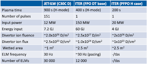
Figure 20. Comparison of the quasi-steady-state campaign in JET ILW with plasmas in different ITER operational phases.
Download figure:
Standard image High-resolution image
The measured and modelled physics processes of W erosion described in this paper can be transferred empirically or with the aid of ERO code simulations to ITER. The latter is foreseen in the near future considering appropriate ITER background plasmas for the different operational phases. The outer divertor conditions in the unseeded C30C JET H-mode plasmas reflect an intolerable divertor scenario in ITER full current plasmas in FPO as the allowed steady-state heat load limitations would be exceeded and the divertor PFCs damaged. However, it might represent transient conditions or operation at lower plasma current and magnetic field which will be applied during the commissioning phase (PFPO) of ITER [28].
In ITER impinging Be ions will not cause relevant W erosion in the inter-ELM phase of H-mode discharges, but intra-ELM sputtering will solely define the W gross erosion in the divertor. The choice of the fuel species will determine the degree of gross W erosion and largest erosion is expected in DT (FPO) and in He plasmas (PFPO). Additionally, the fraction of seeding ions, Ne or N, in the impinging ion mix needs to be considered in the estimation of the W gross source, in particular during the intra-ELM phase. However, the high observed (prompt) re-deposition factors will help to minimise the net W erosion source assuming the ELMs are controlled and reduced in strength which is a prerequisite for the ITER divertor from the point of view of tolerable heat loads at divertor PFCs [28]. The lifetime of the W divertor would be greatly improved as well as the residual W flux into the confined plasma reduced if full ELM suppression in ITER would be achieved.
Acknowledgments
This work has been carried out within the framework of the EUROfusion Consortium and has received funding from the Euratom research and training programme 2014–2018 and 2019–2020 under Grant agreement No. 633053. The views and opinions expressed herein do not necessarily reflect those of the European Commission.