


Abstract
The first EAST (Experimental Advanced Superconducting Tokamak) plasma ignited in 2006 with non-actively cooled steel plates as the plasma-facing materials and components (PFMCs) which were then upgraded into full graphite tiles bolted onto water-cooled copper heat sinks in 2008. The first wall was changed further into molybdenum alloy in 2012, while keeping the graphite for both the upper and lower divertors. With the rapid increase in heating and current driving power in EAST, the W/Cu divertor project was launched around the end of 2012, aiming at achieving actively cooled full W/Cu-PFCs for the upper divertor, with heat removal capability up to 10 MW m−2. The W/Cu upper divertor was finished in the spring of 2014, consisting of 80 cassette bodies toroidally assembled. Commissioning of the EAST upper W/Cu divertor in 2014 was unsatisfactory and then several practical measures were implemented to improve the design, welding quality and reliability, which helped us achieve successful commissioning in the 2015 Spring Campaign. In collaboration with the IO and CEA teams, we have demonstrated our technological capability to remove heat loads of 5000 cycles at 10 MW m−2 and 1000 cycles at 20 MW m−2 for the small scale monoblock mockups, and surprisingly over 300 cycles at 20 MW m−2 for the flat-tile ones. The experience and lessons we learned from batch production and commissioning are undoubtedly valuable for ITER (International Thermonuclear Experimental Reactor) engineering validation and tungsten-related plasma physics.
Export citation and abstract BibTeX RIS

Original content from this work may be used under the terms of the Creative Commons Attribution 3.0 licence. Any further distribution of this work must maintain attribution to the author(s) and the title of the work, journal citation and DOI.
1. Introduction
The development of plasma-facing components (PFCs) for the EAST (Experimental Advanced Superconducting Tokamak) device has a long history. The first EAST plasma ignited in 2006 with non-actively cooled stainless steel plates as the sole plasma-facing materials and components (PFMCs) which were then upgraded into full graphite tiles bolted onto water-cooled copper heat sinks in 2008, capable of removing heat loads up to 1–2 MW m−2 [1, 2], as shown in figure 1. With increasing use of lithium for wall conditioning, the first wall PFM of EAST was changed into chemically more compatible molybdenum alloy (TZM) in 2012, while still keeping graphite as the PFM for both the upper and lower divertors [3]. With the rapid increase in heating and current driving (H&CD) power in EAST recently, the W/Cu divertor project was formally launched around the end of 2012, aiming at actively cooled full W/Cu-PFCs for the upper divertor around 2013–2014, with heat removal capability up to 10 MW m−2 [3, 4]. The W/Cu upper divertor was finished in the spring of 2014, consisting of about 15 000 W monoblocks for 160 vertical targets and 24 000 W flat tiles for 160 baffles and 80 domes, on 80 cassette bodies toroidally assembled [4, 5]. Commissioning of the EAST upper W/Cu divertor in 2014 failed due mainly to leaks of the e-beam welding between the cooling tube and manifold box. After the campaign, we examined the leaking PFCs and reviewed the whole process, and then implemented several practical measures to improve the connection design, component welding quality and installation welding reliability, which helped us achieve successful commissioning in 2015 and smooth operation in the following campaigns.
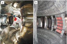
Figure 1. EAST PFMCs, (a) stainless steel plates in 2006 and (b) full SiC/C tiles in 2008.
Download figure:
Standard image High-resolution imageIn this paper, the details of the development of the PFCs for EAST will be described in the following four sections. Firstly, thick SiC coatings on doped graphite (GBST1308) have been developed and applied to EAST as PFM, and vacuum plasma sprayed (VPS) W coatings on a Cu heat sink were also studied. Secondly, the development of ITER (International Thermonuclear Experimental Reactor)-like W/Cu divertor components for EAST has been introduced, from design to manufacturing. Thirdly, high heat flux (HHF) testing of the W/Cu PFCs, both the monoblock and flat types, has been performed and outstanding results have been demonstrated. Finally, the operational performance of the EAST W/Cu upper divertor is shown, including some observed issues and optimization measures.
2. Development of SiC/C and W coating materials for EAST
In order to reduce chemical erosion and hydrogen isotope retention in the carbon based materials (CBM), thick SiC coatings on doped graphite GBST1308 were developed at the Shan'xi Institute of Coal Chemistry, Chinese Academy of Sciences (ASICC) by chemical vapor infiltration of Si into the graphite tiles followed by reactions between Si and C [6, 7]. Figure 2 shows the SEM images of the SiC coatings. It was observed that the thickness of the SiC coating was ~100 μm and the size of the crystal was ~20 μm. The GBST1308 tiles coated with SiC, being bolted to the active cooling heat sink, have been used as the PFM for the EAST device since 2008. A significant improvement in the performance of the plasma was observed and stable DN discharges over 60 s were achieved in the 2009 Spring Campaign.
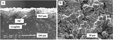
Figure 2. SEM images of the (a) cross-section and (b) surface of the SiC coatings.
Download figure:
Standard image High-resolution imageWith the increase in the heating and driving power in EAST, VPS-W coatings on a Cu heat sink were developed at the Guangzhou Research Institute of Nonferrous Metals (GZRINM) and the Shanghai Institute of Ceramics, Chinese Academy of Sciences (ASSIC) [8–10]. In order to reduce thermal stresses, a W/Cu gradient interlayer of 0.2–0.3 mm was prepared before spraying pure W coating. With at least five steps change of the feeding ratio of Cu and W powders, the composition of the interlayer gradually varied from pure Cu to pure W. Thick pure W coatings of >1 mm were then deposited on the interlayer. Figure 3 shows typical SEM images of the VPS-W coatings with transition layer of the lamellar graded W/Cu. The coatings have a porosity < 10% and an oxygen content of 0.4 wt%. The thermal conductivity of the coatings was measured by the laser flash method and its value reached 80 W/m/K. In order to reduce thermal stress and prohibit the spreading of cracks in the W coatings, castellation has been introduced, and was made at the surface of the heat sink before the coating process.
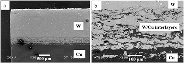
Figure 3. Cross-section images of VPS-W/Cu sample with the magnifications of (a) ×30 and (b) ×200 showing the gradient W/Cu interlayers.
Download figure:
Standard image High-resolution image3. Development of ITER-like W/Cu PFCs for the EAST divertor
Figure 4 shows a view of the entire EAST PFMC as it has existed since 2014. The EAST W/Cu upper divertor was designed as a modular structure [5, 11]. There are 80 modules being supported by the inner rail, outer rail and middle support in the vacuum vessel. Each divertor module includes a cassette body (CB) and three PFCs, namely the inner target (IT), outer target (OT), and DOME, as shown in figure 5. The CB is a stainless-steel weldment, acting as the support for the PFCs. There are 4 W/Cu monoblock plasma-facing units (PFUs) for the IT and 5 PFUs for the OT which are connected to the flat-tile baffles and the manifold boxes by electron beam welding (EBW). The manifold box acts as the cooling connection between the W/Cu monoblock PFU and the CB to accommodate the very limited space. The DOME component consists of an upper plate and a lower plate which were joined by EBW as well. Figure 6 shows details of the W/Cu PFCs for the EAST upper divertor.
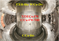
Figure 4. A view of the entire EAST PFMC as it has existed since 2014, including an ITER-like full W/Cu upper divertor consisting of 80 sets of assembled PFC/CB, full C tile lower divertors, TZM tile first walls, and C tile shinethroughs for neutral beams.
Download figure:
Standard image High-resolution image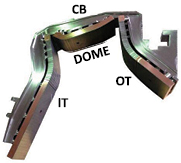
Figure 5. Assembled W/Cu divertor module consisting of CB, IT, OT and DOME.
Download figure:
Standard image High-resolution image
Figure 6. Details of W/Cu PFCs for one module, with use of nine monoblock PFUs, three flat-tile PFUs, and two manifold boxes.
Download figure:
Standard image High-resolution imageThe EAST team has devoted a tremendous amount of time and energy into the development of two different types of actively cooled W/Cu PFCs for the project [12–18]. The monoblock PFCs for the vertical targets were manufactured by hot isostatic pressing (HIP) for cladding oxygen free Cu (OFC) of 1 mm thick to the inner surface of the W monoblocks at 900 °C, and then HIPing at 600 °C for the bonding between the cladded monoblocks and the CuCrZr cooling tube (inner diameter of 12 mm and wall thickness of 1.5 mm). Figure 7 shows the W/Cu monoblock and the PFU for EAST upper divertor. The dimensions of the monoblock are 12 mm (poloidal) × (25–28)mm (toroidal) × 26 mm (radial). Three monoblocks in one PFU are joined to the supporting legs by brazing, and the supporting legs are fastened to the CB via pin insertions. The flat-tile PFCs for the baffles and domes are manufactured by casting OFC onto the rear side of the W tiles at 1200 °C firstly, followed by the HIPing of the W/OFC tiles onto the CuCrZr heat sink plate at 600 °C.

Figure 7. (a) W/Cu monoblock; (b) SEM image of the W/Cu joint and (c) PFU for EAST upper divertor.
Download figure:
Standard image High-resolution imageIn order to control the bonding quality and ensure the lifetime of the PFCs together with the safety of the EAST device, a non-destructive testing (NDT) quality control system has been established. The inspection sensor for the monoblocks and PFUs, emitting and receiving ultrasonic waves laterally at a frequency of 15 MHz, is rotatable and insertable in the CuCrZr tube to detect defects at the W/Cu/CuCrZr interfaces. From the C-scan images of the reference sample with flat bottom holes, the amplitude response caused by the 1 mm hole at the interface of Cu/CuCrZr can be distinguished clearly based on the difference in properties between different materials, as shown in figure 8. For the flat-tile PFCs, the conventional water-gap ultrasonic technique has been used to inspect the bonding quality and figure 9 shows the set-up. A minimum defect with a diameter of 1 mm at the interface can be detected using a focus ultrasonic probe at a frequency of 10 MHz. The acceptance criterion for the W/Cu and Cu/CuCrZr joints of the W/Cu monoblock PFUs is that no defects shall be greater than 2 × 3 mm, and for the flat-tile PFCs, it requires that no defects should be greater than Φ2 mm.
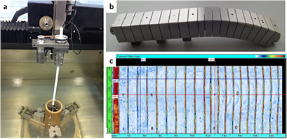
Figure 8. (a) Ultrasonic set-up of the monoblocks and PFUs, (b) reference sample for calibration with flat bottom holes, and (c) C-scan image of the reference sample.
Download figure:
Standard image High-resolution image
Figure 9. (a) Ultrasonic set-up and (b) C-scan images of the flat-tile PFCs.
Download figure:
Standard image High-resolution imageThe W/Cu PFUs were then integrated into the PFCs by e-beam welding (EBW) using an e-beam device as shown in figure 10, with the highest acceleration voltage of 60 kV and current of 100 mA, working pressure less than 1 × 10⁻³ Pa, and dimensions of 1.4 × 1 × 1 m. In the practical application, a welding current ranging from 20–50 mA was used for different kinds of joints. All the joinings, e.g. between the monoblock units and the flat baffle, between the monoblock units and the manifold box, between two half plates for the DOME, between the supporting legs and the CuCrZr baffle plate, and between the inlet/outlet cooling tubes and the baffle/manifold/DOME were welded with this device. In order to control the accuracy of the shape and dimensions, special clamp tools were designed and used for the EBW process, as shown in figure 11. A seam with a depth of 3 mm which is required for all of joints can be obtained with a typical e-beam current of 30 mA.

Figure 10. E-beam welding device.
Download figure:
Standard image High-resolution image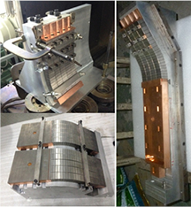
Figure 11. Clamps for EBW.
Download figure:
Standard image High-resolution imageDuring the operation of EAST, the W/Cu PFCs should be heated to over 200 °C and cooled by pressurized water. To evaluate the quality and reliability of the welding and ensure the safety of the EAST device, helium leak detection was performed on each PFC with an acceptance criterion of lower than 1 × 10⁻¹⁰ Pa · m3 · s−1. Figure 12 shows the apparatus used for the pressured helium detection, consisting of a heating system, a vacuum system, and a measurement system. During testing, the PFCs were heated up to 180 °C and the CuCrZr tubes/channels were pressurized with helium gas to 1.5 MPa for 20 min. The gas pumped from the vacuum chamber was analyzed by a helium spectrometer with the minimum detectable leak rate of 1 × 10⁻¹¹ Pa · m3 · s−1.

Figure 12. Apparatus for helium leak detection.
Download figure:
Standard image High-resolution imageAfter the leak testing, the W/Cu PFCs were installed and connected to the stainless steel brackets on the CB using insertion pins and their plasma-facing surface profile was measured and controlled by a robotic-arm measurement instrument. The cooling tubes/channels of the IV, OT and DOME were connected together through the CB acting as a bridge. The Inconel connecting pipes between PFCs and CB were bonded to the PFCs' CuCrZr back plates (see figure 6) by means of EBW from the inner side at AT&M, and bonded directly to the CB by TIG welding at ASIPP. After integration of the PFCs and CB, vacuum leak testing for the whole PFCs/CB module was performed again at room temperature. The allowable leak rate was less than 10−10 Pa · m3 · s−1 for each module. Then, the modules were located on the rails in the EAST vacuum vessel, and fastened by wedges and bolts with small adjustments for alignment purposes. While the cooling water inlets/outlets of the modules were welded to the manifold of the general water supply system, the cooling circuit was closed and then pumped down for the whole divertor system leak test. After the whole EAST vacuum vessel was pumped down, the divertor circuit was pressurized with He up to 1.0 MPa for a leak test again and the maximum allowable leakage is 5 × 10⁻⁸ Pa · m3 · s−1.
4. HHF test of W/Cu PFCs
An assessment of the behavior of the PFCs under cycling heat loads is essential to qualify the PFCs due to their high number of operating cycles and the expected surface heat loads. A W/Cu monoblock mockup was tested by the EMS-60 electron beam facility of at the Southwestern Institute of Physics (SWIP) (Chengdu [12]). This mockup survived 1000 cycles of heat loads at 8.4 MW m−2 with cooling water of 0.23 l s−1, 20 °C. Thermal fatigue testing of the W/Cu monoblock mockups was also carried out at the GLADIS facility at IPP Garching. No damage was detected after testing of 300 cycles at 10 MW m−2 with cooling water of 0.57 l s−1, 20 °C. The full-scale W/Cu monoblock PFUs for EAST were tested via an e-beam facility with a power of 6 kW at Beijing Zhongke Electric Co. Ltd. Only one monoblock was tested due to the limitation of the electron beam power. Heat loads were applied 15 s on and 15 s off with cooling water of 0.46 l s−1, 20 °C. The W/Cu monoblock PFUs survived 1000 cycles of heat loads at 10 MW m−2 and no damage was observed. The maximum temperature of the monoblock surface was about 1200 °C, as shown in figure 13. The flat-tile W/Cu mockups were also tested by this facility with cooling water of 0.46 l s−1, 20 °C, and all the mockups withstood 1000 cycles at 5 MW m−2 with the surface temperature of the W tiles at about 500 °C.
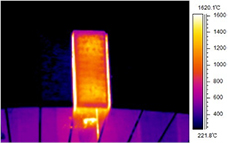
Figure 13. Temperature distribution of the monoblock surface measured by an IR camera during thermal fatigue testing.
Download figure:
Standard image High-resolution imageRecently, in collaboration with IO, we have further demonstrated our technology capability to remove heat loads of 5000 cycles at 10 MW m−2 and 1000 cycles at 20 MW m−2 for the six small scale monoblock mockups in accordance with the qualification program [19]. The HHF test included 5000 cycles at 10 MW m−2, 300 cycles at 20 MW m−2 and an additional 700 cycles at 20 MW m−2, and was performed by IDTF (ITER Divertor Testing Facility, San Petersburg) [20]. Figure 14 shows the six small-scale monoblock mockups mounted in IDTF for the HHF test. The heat load pattern was set as 10 s on and 10 s off. The surface temperature was measured by an IR camera and pyrometers, and the absorbed heat flux was obtained by global calorimetry from the measurement of the temperature by thermocouples mounted at the inlet and the outlet of the cooling water with a pressure of 3.9 MPa, an inlet temperature of 70 °C and a flow rate of ~1.24 l s−1. All mockups passed the HHF test successfully in the sense that no significant increase in surface temperature along the cycling was observed. After the 5000 cycles at 10 MW m−2, no visible damage was observed. Macro-cracks [21, 22] that did not impair the thermal performance, appeared in 2 out of 24 monoblocks after 300 cycles at 20 MW m−2 and 9 out of 24 monoblocks after additional 700 cycles of testing at 20 MW m−2.

Figure 14. HHF testing for six W/Cu monoblock mockups (28 mm × 26 mm × 86 mm each, consisting of seven monoblocks) by the IO team on IDTF, showing here good performance after IO required heat loads of 5000 cycles at 10 MW m−2 + 300 cycles at 20 MW m−2.
Download figure:
Standard image High-resolution imageIn collaboration with the CEA-WEST team, we have prepared four test mockups of W/Cu PFCs (two monoblock mockups and two flat-tile mockups) for CEA's Tungsten Environment in Steady-state Tokamak (WEST) project, which showed outstanding performance in the HHF tests carried out by the WEST team on JUDITH-1. One W block of the W/Cu monoblock mockup successfully withstood 1200 cycles of heat loads at 10 MW m−2 and 300 cycles at 20 MW m−2, and the other one withstood 500 cycles at 10 MW m−2 and 500 cycles at 20 MW m−2. One W/Cu flat-tile mockup successfully withstood 102 cycles at 10 MW m−2, 102 cycles at 15 MW m−2 and 302 cycles at 20 MW m−2 in succession; the other withstood 302 cycles at 10 MW m−2, 102 cycles at 15 MW m−2 and 102 cycles at 20 MW m−2. The results of the flat-tile mockups are far beyond the ITER design requirement of 5 MW m−2, which, to our knowledge, have set records. Figure 15 shows the flat-tile mockup tested by the WEST team on JUDITH-1.

Figure 15. HHF testing for a flat-tile mockup (28 × 26 × 86 mm with seven 2 mm thick tiles) by the WEST team on JUDITH-1, showing excellent performance.
Download figure:
Standard image High-resolution image5. Performance of EAST W/Cu PFCs during campaigns
In the 2014 EAST campaign, leakage on one module of the W divertor was found during the nitrogen baking phase at 180 °C prior to the plasma discharges, and the cooling circuit covering the leaking module was evacuated. EAST was operated only with a lower single null plasma configuration for the campaign. During the campaign, 982 downward vertical displacement events (VDEs), 239 upward VDEs and 157 middle plane disruptions were recorded. Halo current measurement showed a maximum halo current onto a single divertor module up to 10 kA for 500 kA plasma current upward disruptions. At the end of the campaign, another baking up to 280 °C was carried out to disclose possible weak points sensitive to thermal stresses.
After the campaign, we tried to localize the leak points. As the cooling water system consisted of eight independent sub-circuits for all 80 modules, the first step was to inspect each circuit to localize which circuit had leaked. The second step was to disassemble the modules for a further leak check. Table 1 lists the detailed leakages after the 2014 campaign, showing that most of the leak points were located at the EBW seams except the last two (one from the CuCrZr heat sink, and the other from the W monoblock). These EBW failures may be caused by thermal stress, electro-magnetic force, and a weak welding seam (e.g. defects in the seam and/or too shallow welding).
Table 1. Leakage in 2014 EAST campaign.
| Leakage type | Leakage count |
|---|---|
| Plate-plate welding seams of vertical targets | 6 |
| Tube-plate welding seams of DOME | 3 |
| Tube-plate welding seams of vertical targets | 2 |
| Heat-sink of baffle | 1 |
| Monoblocks | 1 |
We then examined the leaking PFCs carefully and reviewed the whole process from design and manufacturing through installation, and then put forward several practical measures and conducted corresponding R&D activities, to improve the connection design, component welding quality and installation welding reliability. These measures helped us pass smoothly the baking and even the discharge phases in the following 2015 campaigns.
Firstly, a specific ultrasonic technique to test the welding seams between the cooling tube and the CuCrZr plate was developed to ensure that the EBW depth was circularly averaged about 2.5–3.0 mm, as shown schematically in figure 16. This testing method is similar to the spiral ultrasonic method we have developed for the monoblock PFUs [13–15]. This quantitative measure for quality control of the EBW seams, together with the helium leak check, an indirect testing for the welding seams, played a significant role in the manufacturing and the operation of the W/Cu PFCs, which has become a standard NDT combination for the following repair and manufacture of the W/Cu PFCs.
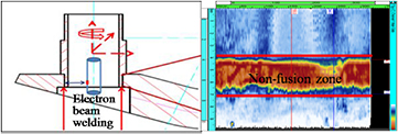
Figure 16. NDT method directly measuring the circular welding depth distribution.
Download figure:
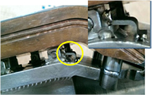
Standard image High-resolution imageThe second measure is to optimize the connection structure of the cooling tubes. In the previous design, the cooling tubes were TIG-welded directly to the CB, leading probably to high thermal stress buildup onto the EBW seams during baking and abnormal events. In order to reduce the thermal stress, the design of the TIG welding between the tubes and the CB was changed into a direct and flexible connection using soft bellows between the tubes, as shown in figure 17.

Figure 17. Improvement in connection design for the cooling tubes to reduce thermal stress buildup.
Download figure:
Standard image High-resolution imageFinally, helium leak detection was performed as the final NDT on each assembled divertor module as a whole at up to 250 °C to better simulate the actual environment during the baking phase in EAST. In comparison, previously, the leak detection at elevated temperature was only performed for the single W/Cu PFCs, and for the assembled divertor modules, the leak detection was carried out only at room temperature.
In addition, stainless steel electric straps were welded between the PFC supporting legs and the CB, enhancing the halo current flowing from the PFC to the CB through the straps, thus reducing the halo current flowing through the soft bellows, as shown in figure 18. The electric resistance between the PFCs and the CB was measured and the current flow path was calculated carefully. The results showed around 1/3 of the halo current would flow through straps to the CB and the bellows could be protected properly.
Figure 18. Welded straps between the legs and the CB to reduce the EM force on the soft bellows.
Download figure:
Standard image High-resolution image
In the 2015 EAST campaigns, the W/Cu upper divertor survived after three weeks of baking at 200 °C. At the end of the campaign, tens of shots of upper single null (USN) discharges were achieved with the input heating power of ~4 MW. And an H-mode lasting 10 s was achieved for one shot with a pulse length of 30 s. This campaign demonstrated the successful commissioning of the W/Cu divertor after taking significant measures for quality and safety control. In the 2016 campaigns, the W/Cu upper divertor withstood much more severe discharges and no leaks occurred. A one minute long pulse H-mode discharge (shot 67341) was achieved [23].
6. Summary and outlook
W has been selected as the PFM for the whole ITER divertor from day one and the technologies for batch-scale manufacture of the W/Cu-PFCs are still far from maturity, not to mention testing under practical long pulse tokamak plasmas. So far, key technologies being developed at ASIPP have already shown great HHF performance in laboratory testing. The experience and lessons obtained from batch production, further commissioning and plasma operation on EAST are undoubtedly valuable for ITER engineering validation and key physics related to W.
Acknowledgments
This work is partially funded by the National Natural Science Foundation of China under contract nos. 11305213 and 11575242, the National Magnetic Confinement Fusion Science Program under contract nos. 2013GB105001 and 2013GB105002, Chinese Academy of Sciences Maintenance and Renovation Program of the Mega-Project of Science: Maintenance and Renovation Project of Upper Divertors in EAST.
Disclaimer
The views and opinions expressed herein do not necessarily reflect those of the ITER Organization.