


Abstract
New experiments in the low-torque ITER Q = 10 scenario on DIII-D demonstrate that n = 1 magnetic fields from a single row of ex-vessel control coils enable operation at ITER performance metrics in the presence of applied non-axisymmetric magnetic fields from a test blanket module (TBM) mock-up coil. With n = 1 compensation, operation below the ITER-equivalent injected torque is successful at three times the ITER equivalent toroidal magnetic field ripple for a pair of TBMs in one equatorial port, whereas the uncompensated TBM field leads to rotation collapse, loss of H-mode and plasma current disruption. In companion experiments at high plasma beta, where the n = 1 plasma response is enhanced, uncorrected TBM fields degrade energy confinement and the plasma angular momentum while increasing fast ion losses; however, disruptions are not routinely encountered owing to increased levels of injected neutral beam torque. In this regime, n = 1 field compensation leads to recovery of a dominant fraction of the TBM-induced plasma pressure and rotation degradation, and an 80% reduction in the heat load to the first wall. These results show that the n = 1 plasma response plays a dominant role in determining plasma stability, and that n = 1 field compensation alone not only recovers most of the impact on plasma performance of the TBM, but also protects the first wall from potentially damaging heat flux. Despite these benefits, plasma rotation braking from the TBM fields cannot be fully recovered using standard error field control. Given the uncertainty in extrapolation of these results to the ITER configuration, it is prudent to design the TBMs with as low a ferromagnetic mass as possible without jeopardizing the TBM mission.
Export citation and abstract BibTeX RIS
1. Introduction
Test blanket modules (TBMs) will be installed in ITER to assess tritium-breeding blanket technology [1]. The ITER TBMs are themselves mock-ups of the breeding blankets envisioned for DEMO [2]. A maximum of 20 mg day−1 of tritium will be produced within ITER's TBMs by exposing lithium inside the TBMs to the neutrons generated by the fusion reactions occurring in the plasma [3]. TBM technology will be essential for achieving the degree of tritium self-sufficiency required for the success of both future burning plasma experiments and demonstration reactors [4]. In ITER, three pairs of six different TBM designs will be located in three equatorial ports separated toroidally by a total of 40°. Although the details of each TBM design differ, all will use structural material made from martensitic steel alloy, a high-temperature and neutron-tolerant material that is also ferromagnetic. This material will increase the local magnetic field permeating the TBMs, resulting in a reduction of the field in the plasma and an enhancement of the local magnetic field ripple [5].
The spatially localized TBM error fields differ substantially from the error fields typically encountered in tokamaks (e.g. error fields from coil misalignments and intentionally applied magnetic perturbations) [6]. The lack of theoretical understanding in this area has motivated experimental studies on the DIII-D tokamak since 2009, in collaboration with the ITER organization. The main goals have been to assess the impact on plasma performance and to develop control strategies that can adequately mitigate any deleterious effects. Initial survey experiments in high-torque/rotation scenarios revealed that many of the possible TBM effects proposed before the first DIII-D experiments are negligible [7]. These studies showed that, in rotating H-mode plasmas matching the ITER shape and plasma beta, the TBM error field mainly decreases the plasma rotation and to a lesser degree the energy and particle confinement (attributed to reduced rotation and fast ion losses). The observed plasma rotation braking was consistent with an edge-localized non-resonant magnetic field torque.
While TBM effects are modest at a normalized plasma beta ( ) of 1.8, TBM-induced degradations in density, stored energy and
  were found to increase dramatically with
  , with each parameter reduced by 15% at
  . (Here
  is the ratio of
  where β is the ratio of the plasma to the magnetic field energy,
  , and the normalized plasma current IN is the ratio of the plasma current Ip to the magnetic field B and minor radius a,
  .) The reduction in
  was not always the same as the change in density, indicating that the plasma temperature and/or fast ion content was also reduced. Rotation braking from the TBM field also increased with
  , with a reduction of up to 60%. In L-mode plasmas, uncorrected TBM fields were found to limit low-density operation by increasing the error field threshold for the onset of n = 1 locked (non-rotating) modes [5]. (Here n is the toroidal mode number.) Fortunately, low-density access was entirely recovered with optimal n = 1 error field compensation (EFC) using two rows of in-vessel control coils, which gives confidence that corrected TBM fields will not limit performance during early ITER operations provided ex-vessel coils provide similar performance.
Control experiments were extended in 2011 to H-mode plasmas with toroidal torque near 3.5 N m from neutral beam injection (NBI) [8]. The discharges studied had a safety factor of q95 = 4.1,  and a toroidal angular momentum (
 ) of 0.32 Nms, parameters chosen to decrease the effects of neoclassical tearing modes (NTM) in order to achieve highly reproducible plasma conditions. (Here q95 is the safety factor at the surface enclosing 95% of the poloidal flux.) Despite extensive efforts to minimize the n = 1 error field with in-vessel coils, it was found that optimized EFC could only recover approximately a quarter of the 20% decrease in rotation attributed to the TBM error field. The compensation currents yielding the largest rotation recovery almost completely suppressed the magnetic n = 1 plasma response as measured at the outboard midplane. Therefore, it was concluded that the residual rotation braking was due either to residual n = 1 fields not minimized by the compensation fields or to n > 1 magnetic fields.
These previous results highlight a few open high-priority research topics in support of the ITER TBM program. First, it should be noted that while the control experiments in H-mode plasmas have successfully demonstrated the degree to which TBM fields could be compensated, the results were obtained in discharges with relatively high levels of applied torque, a regime where plasma flow potentially inhibits penetration of resonant field errors and stabilizes tearing modes. Since TBM fields are known to indirectly excite resonant error fields [5], it is important to investigate TBM effects at ITER-relevant levels of applied torque in order to confidently extrapolate DIII-D results to ITER. In addition, the strong decrease in confinement with plasma beta with TBM fields above  is a cause for concern during the initial ITER D-T campaign, when increased plasma pressure may be desirable for achieving the Q = 10 mission. Since it would be possible to remove the TBM modules prior to these experiments, it is important to demonstrate experimentally whether or not confinement could be maintained with ITER-relevant control actuators. Finally, although empirical methods are available for optimizing error field correction, it would be more desirable to have a validated theoretical model to assess TBM effects in various ITER scenarios, to provide a prediction of the optimal error field correction and a means to design control fields consistent with other three-dimensional (3D) field control schemes that may be needed in ITER, such as RMP ELM suppression and rotation control.
Recent progress in DIII-D has been made in sustaining low-torque H-mode plasmas, allowing TBM effects to be studied in plasmas that attain high fidelity to the ITER Q = 10 15 MA scenario [10]. Here, we report on new experiments focused on assessing and controlling TBM effects in this scenario. In section 2, we show that this plasma regime is susceptible to rotation collapse and subsequent plasma current disruption induced by uncorrected TBM fields. As seen in low-density L-mode plasmas, loss of stability can be avoided and ITER performance metrics sustained using only n = 1 compensation fields generated by a single row of ex-vessel control coils similar to the equatorial correction coils planned for ITER. In section 3, we discuss in more detail the empirical optimization of the EFC currents before comparing the results with predictions from physics-based models of the TBM torque. It is shown that existing models do not accurately predict compensation currents sufficiently well to avoid the need for empirical methods to optimize the compensation fields. This implies that the ITER error field control system must have sufficient capability to support empirical error field optimization strategies. Since reduced plasma current scenarios are associated with greater stability but require higher plasma pressures to achieve high fusion performance, it is important to assess whether TBM fields will significantly limit confinement at high beta where external fields can be amplified well above the vacuum field. Therefore, in section 4, results from companion H-mode experiments at high  are presented, which again show that n = 1 EFC of TBM fields is sufficient to recover degradations in
  and rotation, as well as reduce heat loads associated with the TBM. Finally, in section 5, we discuss access to low-torque operation and the margin for stable operation with TBM fields.
2. Impact of the TBM error field on ITER Q = 10 discharges at low torque
In this section, we show that, in contrast to previous results at high torque, low-torque ITER scenarios in DIII-D are susceptible to rotation collapse and subsequent plasma current disruption following application of uncorrected TBM fields. However, even a single row of ex-vessel control coils can be used to enable operation at ITER performance metrics.
2.1. Experimental setup
ITER operational scenarios have been developed on DIII-D to help understand the techniques required for ITER to meet its physics and technology goals [12]. Recently, sustained operation of the ITER scenario envisioned for ITER Q = 10 experiments has been achieved in DIII-D at low applied torque for multiple resistive relaxation times [10]. These discharges match the ITER performance metrics including a scaled (reduced by a factor of 3.7) lower single null boundary shape (shown in figure 1), normalized plasma current  corresponding to q95 = 3.2,
  and an energy confinement factor (H98Y2) of 1.05. (H98Y2 is the enhancement factor above the H-mode confinement scaling IPB98(y,2) [11].) A key challenge had been in learning how to maintain stability, as these discharges are highly susceptible to rotation collapse—a problem further exacerbated by TBM-like error fields. Since plasma reproducibility is found to generally improve with plasma density, the discharges reported here use significant fueling to maintain high line-averaged electron plasma densities near
 , corresponding to Greenwald fractions of 0.65, which is close to the expected ITER Q = 10 operational point [13].
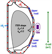
Figure 1. Poloidal cross section of the ITER Q = 10 scenario in DIII-D and the locations of the TBM coils (purple, racetrack coil and solenoid), the ex-vessel C-coil (green) and the in-vessel I-coil (blue). C-coil and I-coil (six toroidal sections each) were used for n = 1 and n = 2 compensation, respectively. Toroidal arrays of poloidal magnetic field sensors ( ) on the centerpost (light blue) detect the low-frequency plasma response to DC 3D fields while rotating instabilities (tearing modes, sawtooth precursors) are observed using both toroidal and poloidal arrays of Mirnov probes,
  (red).
Download figure:
Standard image High-resolution imageThese plasmas are heated with up to 4.4 MW of NBI with beamlines pointing in both toroidal directions, which decouples the NBI heating power from the applied torque (TNBI), allowing independent control of  and rotation. Feedforward beam power and torque control are employed to study
  values in the range of 1.8–2.2 whenever the impact of the applied 3D fields on energy and momentum transport is documented. Feedback control of
  is used in experiments when the applied torque is varied during a discharge and constant
  is desired at a fixed torque. Since reproducibility worsens as the applied torque is decreased below 1 N m, only transient experiments are pursued at torque values below this level. (See [10] for a discussion of the relevant stability issues under investigation.)
Error fields similar to those expected from the ITER TBMs are generated in DIII-D using a TBM simulator (see [5] for details), which is a set of electromagnetic coils: two 60-turn racetrack coils surrounding one 330-turn solenoid. These coils, located on the low-field side of the torus and centered vertically at the midplane (figure 1), mimic the toroidal and poloidal magnetization of a pair of representative TBMs in one equatorial port. In ITER, all six TBM designs differ in the exact amount of ferromagnetic material, but all will target a design with less than 1.3 tons of ferritic steel [2], which is calculated to produce a local magnetic field ripple (δ) of 1.2% [5]. The standard definition of ripple is used:  . Since the scaling of TBM effects from DIII-D to ITER is not well established, TBM fields of up to 3% total magnetic field ripple, as calculated at the maximum radial location on the plasma boundary (
 ), are investigated to help resolve the operational limits and for comparison against numerical simulation. The applied ripple in each experiment varies somewhat depending on the plasma shape and TBM current so it is reported throughout the manuscript when appropriate. Although the extrapolation from DIII-D results to ITER is not well understood, the maximum field strength of three times the expected ITER field ripple was motivated by particle transport simulations with the Monte Carlo code F3D-OFMC, which indicate thermal particle losses scale linearly with the number of TBM ports [14].
The recent experiments focused on assessing the capabilities of ITER-like actuators to control TBM effects. As in ITER, the DIII-D experiments utilize a row of ex-vessel mid-plane coils (the 'C-coil') for compensation of the n = 1 harmonic of the intrinsic error field and the TBM field8. Compensation of higher toroidal harmonics, namely n = 2, is achieved using two rows of six internal coils (the 'I-coil') located above and below the midplane. These coil arrays are similar to the upper and lower ITER in-vessel coils to be used for control of edge localized modes (ELMs) [13]9. While the poloidal (m) spectrum of the C-coil is fixed, the m-spectrum of the applied I-coil field can be adjusted via the toroidal phase difference between the upper and lower I-coil arrays ( ) in order to maximize the coupling between the applied field and the dominant plasma mode. For example, the coupling to the dominant n = 2 plasma mode in the ITER scenario, as calculated by perturbed equilibrium codes such as IPEC [17], is maximized for an up–down symmetric coil configuration (
 ), also referred to in the literature as the 'even parity' configuration.
Analysis of EFC algorithms in multiple devices has shown that optimal EFC is achieved by minimizing the drive for the plasma mode that couples most strongly to the total resonant field [15–20]. Although the C-coil m-spectrum cannot be tuned to match the dominant n = 1 plasma mode, it is expected to perform as well as the I-coil. This follows from n = 1 proxy error field studies that have shown that the plasma is insensitive to n = 1 error fields that are orthogonal (i.e. couple weakly) to the dominant mode, which is a kink mode [22, 30].
2.2. Tolerance to TBM error fields
The error field tolerance of the ITER Q = 10 scenario to uncorrected TBM error fields is studied at an applied torque level of 1.1 N m, which is close to the scaled ITER-equivalent applied torque of 0.8 N m [21]. When energized at 3 s, the TBM error field, which reaches a maximum of 2.86% ripple, is found to slow the plasma rotation, leading to the onset of an n = 1 locked mode instability (figure 2). The locked mode is followed by a plasma current disruption that terminates the discharge. This result contrasts previous observations at higher applied torque and lower plasma current where only a reduced level of plasma rotation braking is observed. At low torque, the rotation profile is observed to decrease nearly self-similarly across the profile with no indication of localized braking near rational surfaces (figure 3). Although large sawtooth crashes with inversion radii up to mid-radius and large type-I ELMs are observed as the rotation decreases, these instabilities do not appear to trigger the locked mode. Instead, the onset of the n = 1 locked mode occurs when the rotation near the q = 2 surface decreases to half of the unperturbed (pre-TBM) rotation. A bifurcation at this rotation level arises from error field penetration associated with a locked magnetic island [23].

Figure 2. (top) Time evolution of sawtooth and ELM activity with an uncorrected TBM error field applied leading to (middle) a slowing of the plasma rotation and (bottom) eventual growth of an n = 1 locked mode. The sawtooth crashes are observed in core electron temperature measurements from the electron cyclotron emission (ECE) diagnostic. The ELM activity is seen in visible  emission in the diverter region. The locked mode is detected using an n = 1 fit to measurements of the external poloidal magnetic field (
 ) from a sensor array at the outboard midplane.
Download figure:
Standard image High-resolution image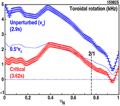
Figure 3. Comparison of the carbon impurity ion toroidal rotation profile (as a function of the normalized poloidal flux  ) from a charge-exchange recombination (CER) diagnostic before the TBM error field is applied (blue) to the critical rotation profile measured just prior to the onset of an n = 1 locked mode (red). The blue dotted line marks half of the rotation without the TBM field applied.
Download figure:
Standard image High-resolution imageA database of TBM-induced locked modes shows a consistent rotation scaling over a wide range of applied torque values (figure 4). The database includes ITER Q = 10 discharges as described above and an ITER similar discharge at lower plasma current ( ), higher beta (
 = 3) and higher applied torque (
 N m). This scaling, also observed in n = 1 locked mode experiments [22], suggests that the toroidal torque balance includes contributions from a resonant electromagnetic braking torque. Unlike resonant magnetic perturbations (RMPs), which displace magnetic field lines more in one radial direction when integrated along an initially closed field line, the magnetic field from the TBM module deflects field lines equally outwards and inwards, making it a purely non-resonant field. Therefore, the resonant magnetic field torque must be generated from perturbed plasma currents associated with the plasma response to the TBM field. Previous studies have shown that the dominant plasma mode contributing to the plasma response is the n = 1 global kink mode [22, 30]. The plasma response leads to enhanced rotation braking at low torque with the rotation level reduced below the threshold required to trigger a 'downward' bifurcation into a 'fully reconnected' state as described by Fitzpatrick [23]. Although NTMs are present in these discharges, they do not appear to cause significant changes in the evolution of rotation or in the onset of n = 1 locked modes.

Figure 4. Scaling of the critical rotation at the q = 2 surface, measured prior to the onset of the n = 1 locked mode, with the unperturbed rotation (no TBM) at the q = 2 surface. The dashed line is half the unperturbed rotation and is not a fit to the data.
Download figure:
Standard image High-resolution image3. Empirical optimization of compensation fields at low torque
3.1. Experimental technique
At the ITER  target, the dominant effect of the TBM field is on the plasma rotation and magnetic plasma response, making these two quantities suitable metrics for identifying the optimal compensation fields. The data are obtained by varying the amplitude I0 and toroidal phase
  of the coil current
  for a given toroidal harmonic (n) in order to either maximize the toroidal angular momentum (
 ), which includes changes in the particle and momentum confinement, or minimize the magnetic plasma response (
 ) [8]. Typically, the empirical optima identified by these two metrics yield similar but not identical optimal currents [16]. (Note that the current at a fixed toroidal location can be recovered using
  .) This approach has been used recently for studying proxy error fields with only a single toroidal harmonic [30]. During the optimization of n = 1 fields, the input torque is set to 2.1 N m and an estimate of the compensation field from the IPEC and PENT [31] codes is applied simultaneously with the TBM field in order to reduce the initial TBM rotation braking, and give some operational headroom at the maximum TBM coil current.
The total control coil current ( tot) can be decomposed into three contributions from currents representing the intrinsic error field (
 intri), the TBM error field (
 TBM) and the varied control current (
 ). Assuming any residual error field generates a torque proportional to
  , the steady-state angular momentum balance implies

where  is the angular momentum confinement time, c is the proportionality constant for the non-axisymmetric field torque,
  is the optimal control current for a given toroidal harmonic and error field source 'cc', and
  is the angular momentum achieved at
  . Here, 'cc' is either 'TBM' when the TBM coil is energized and 'intri' otherwise. Given the errors in the density and rotation measurements, which are about 4%, the error in the measured
  is about 6%. A fit over the widest possible range of coil currents helps to compensate for this error. Equation (1) is consistent with a non-resonant magnetic field torque, and is used here as a fit function to infer the optimal currents. Due to the presence of a non-negligible intrinsic error field in DIII-D, the optimal compensation currents due to the TBM field cannot be measured directly but must be inferred from optimizations with and without the TBM coils energized with
  .
.
3.2. Empirical optimization of n = 1 fields
An initial step in these experiments involves the correction of the n = 1 intrinsic error field  . Attempts to empirically optimize the C-coil currents at low torque (
 N m) were very challenging owing to changes in the NTM and ELM stability during coil current scans including the onset and locking of 3/2 and 2/1 NTMs and ELM-free periods, both of which pollute the dependence of
  on the control field. Therefore, the present best estimate of
  comes from a combined estimate from multiple experimental techniques.
The first technique is referred to in the DIII-D plasma control system as the 'standard algorithm', and provides the optimal coil currents for a given plasma current and toroidal field using the results from 'COMPASS scan' experiments. In these experiments, the amplitude of control fields is ramped at different toroidal phases in Ohmic plasmas in order to identify the critical current level for inducing a non-rotating locked magnetic island [9]. In the complex amplitude space for a given toroidal harmonic, the center of a circle fitted to the critical currents identifies  since a field ramped up from this current offset would lock at the same amplitude independent of the toroidal phase of the applied field. For the targeted plasma conditions, the
  for the C-coil is 1.296 kA at 49°. It is useful to compare other empirical estimates of the optimal currents relative to this estimate by quoting the amplitude multiplier and phase shift (e.g. the standard algorithm has a multiplier of unity and phase shift of 0°).
A second technique for  using the n = 1 C-coil can be determined by identifying the EFC currents that minimize the magnetic plasma response. In this approach, optimal I-coil currents are identified from a database of ITER like H-mode discharges indicating a minimum in the measured n = 1 magnetic plasma response (
 ) inside the vacuum vessel wall at the equatorial midplane on the low-field side. These I-coil currents are then mapped to the C-coil currents by minimizing the drive from the I-coil to the dominant plasma mode as predicted by IPEC. In this approach, the empirically optimized I-coil field is a proxy for the intrinsic error field. The analysis identifies a multiplier and phase shift relative to the standard algorithm of 1.6 and 5°, respectively, which is consistent with an enhancement of the intrinsic error field by the plasma in H-mode relative to the plasma response in lower pressure Ohmic plasmas.
The evolution of  in three discharges where these two estimates were used (figure 5) shows little to no change in plasma performance. During these experiments, only the C-coil EFC was varied: two cases use the standard algorithm and one discharge used the second estimate. Although the time range for comparison was limited by differences in MHD events (e.g. rotating tearing modes),
  is similar during the early phase of the plasma current flattop, suggesting that the estimates are likely to be near the optimal currents or are equidistant from the optimal
  .
.
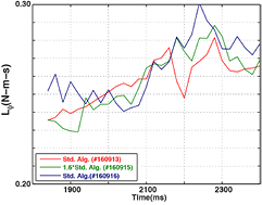
Figure 5. Evolution of  during the early phase of the plasma current flattop for three discharges where the n = 1 error field correction was varied from one shot to the next.
Download figure:
Standard image High-resolution imageA third technique for  comes from scanning the C-coil amplitude and phase during a discharge, monitoring
  and using equation (1) to identify
  . Ideally, the scans would cover a wide range of amplitudes and toroidal phases; however, due to the aforementioned variations in the MHD events and limited experimental time, only a limited range of currents yield meaningful results. Even so, the fits show good agreement with the the previous two estimates for
  (figure 6). As speculated, the first two estimates are equidistant from the inferred value of
  , which has a multiplier and phase shift relative to the standard algorithm of 1.3 and 0°, respectively. This also happens to be the average of the result from the first two techniques.
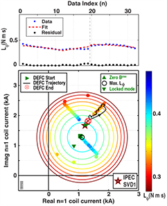
Figure 6. (bottom) Evolution of  for variations in the n = 1 C-coil current without the TBM coils energized (filled circles), and the optimal coil current corresponding to the fitted value of Lopt (open circle). The circular contours are generated by fitting the coefficients of equation (1) to the
  measurements. The blue triangles mark the expected optimal currents from different EFC optimizations including using the onset of locked modes in L-mode plasmas with the same edge safety factor (downward triangle), and zeroing the the magnetic plasma response (upward triangle). (top) Comparison of the measured (blue squares) and fit (red dashed line) values of
  together with the computed residual.
Download figure:
Standard image High-resolution imageA final estimate for  can be obtained using a technique referred to as 'dynamic error field correction'. In this approach, active magnetic feedback (as developed for resistive wall mode control) is enabled after a stationary plasma equilibrium is achieved. A low-pass filter with a relatively long time constant (100 ms) is used to smooth an error signal derived from an n = 1 fit to a toroidal array of poloidal field probes located at the midplane. The error signal is taken with respect to an arbitrary offset measured after the plasma current flattop. Results using the DEFC technique are limited in this target plasma; however, in one discharge where the technique was used, the coil currents initially moved away from the pre-programmed EFC currents only to return to those values later in the discharge. The trajectory is noted in figure 6. In this discharge the pre-programmed values were found by minimizing the plasma response (the second technique), which agrees well with the IPEC prediction of the EFC currents that minimize the coupling of the total field to the dominant n = 1 mode (red star in figure 6).
Table 1 summarizes the various estimates of  . An error estimate of 22% is found between the various methods. The average value taken from the mean of the empirical methods agrees well with the IPEC prediction, which is based on an error field source model for DIII-D.
Table 1. Empirically optimized and theoretically predicted values of C-coil correction of the intrinsic n = 1 DIII-D error field. The average value is taken over the empirical methods.
| Condition |  |
|---|---|
| Standard algorithm | 1.296 kA ∠49° |
Zero  |
2.060 kA ∠54° |
Max.  |
1.696 kA ∠49° |
| DEFC | 2.247 kA ∠54° |
| Average | 1.823 ± 0.430 kA ∠52 ± 3° |
| IPEC SVD1 | 2.06 kA ∠54° |
Empirically optimized values for  tot are obtained via variations of the current in the C-coil with the TBM field applied at 2.94% ripple, and are used to identify
  . The data are obtained in the presence of 4/3 NTMs, which, at large control coil current, can slow down and lock the plasma rotation to the resistive wall leading to disruption (green traces in figure 7). With partial compensation fields applied, the average change in
  due to the TBM field is
 N m s. Multiple discharges are analyzed to identify an extremum
  value that recovers as much as 58% of the partially corrected TBM-induced
  degradation (figure 8). The fit residual is small, indicating that equation (1) captures the dominant variation of
  .
.
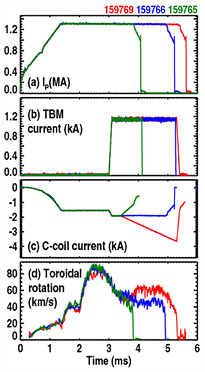
Figure 7. (bottom) Evolution of (a) the plasma current, (b) TBM coil current, (c) current in one of three pairs of C-coils, and (d) the toroidal plasma rotation at  during empirical optimization of the n = 1 compensation field. The rotation increases for certain n = 1 toroidal phases of the applied C-coil field, indicating a reduction in the total 3D field torque.
Download figure:
Standard image High-resolution image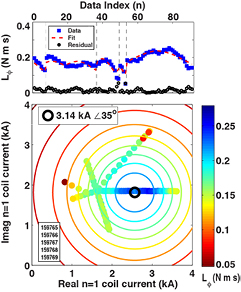
Figure 8. Same as figure 6 but with the TBM coils energized.
Download figure:
Standard image High-resolution image3.3. Comparison with theory
The empirically optimized and theoretically predicted values of  with n = 1 are compared in figure 9 and table 2. The empirically optimized value is over four times larger than that predicted by IPEC–PENT with a toroidal phase difference of 21.1°. However, the optimal value is expected to be closer to the value noted as
  in table 2 since it was successfully used to access operation at near zero applied torque as described in section 5.1. This value was selected during the experiment based on previous results, which showed that IPEC predictions of the optimal correction accurately predict the phase, but underestimate the amplitude [8]. Since a reduction of the n = 1 compensation field by 50% significantly increases the torque threshold for n = 1 locked mode onset (see section 5.1), we can conclude that
  must be quite close to the optimal value. Note that
  is in good agreement with the phase predicted by IPEC–PENT but underestimates the amplitude by a factor of two.

Figure 9. Plot of fitted values of  tot (black) and
  intri (red) taken from the average of the empirical methods together with the inferred value of
  TBM (blue), the IPEC–PENT prediction of
  TBM (cyan), and the value
  TBM used to evaluate access to low torque as discussed in section 5.1 (green). The estimated error in the amplitude of
  TBM is marked.
Download figure:
Standard image High-resolution imageTable 2. Empirically optimized and theoretically predicted values of  .
.
| Condition |  |
|---|---|
 |
0.328 kA ∠−15.6° |
 |
3.140 kA ∠35° |
Average  |
1.823 kA ∠52° |
 |
1.360 kA ∠5.5° |
 |
0.685 kA ∠−14.4° |
Together with results from a previous analysis [8], we conclude that the phase of the optimal compensation currents can be accurately predicted by IPEC–PENT analysis but that the codes consistently underestimate the required amplitude. The reason for the discrepancy found in this analysis is under further investigation. Uncertainty in the determination of the optimal compensation for both the intrinsic error field and the TBM error field could contribute. The estimated uncertainty in the amplitude of  TBM is marked in figure 9, but doesn't fully explain the discrepancy. An important known sensitivity that remains to be quantified is related to the sensitivity of the predicted perturbed fields to the safety factor profile, which is near unity across a large fraction of the minor radius resulting in near zero magnetic shear in the plasma core. The sawtooth instability itself may also play a role to modify the plasma response to the TBM field in a way not captured by linear models.
In these experiments, the EFC optimization based on maximizing the rotation yielded a result ( TBM) that differs from
  in both amplitude and phase. Since previous results have shown rotation optimization to be an accurate method for correcting fields errors, further comments explaining possible reasons for these discrepancies are warranted. First, the dominant fraction of the discrepancy is likely to be due to the fact that the rotation optimization procedure was not continued until a converged result was obtained. Due to limited experimental time and the added challenges of low-torque operation, regions of the n = 1 coil current space near the optimal value remained unexplored (see figure 8). Further studies might have identified a result for
  TBM in better agreement with
  . As mentioned previously, the added challenges of low torque operation include the presence of large-amplitude MHD instabilities (e.g. sawtooth, tearing modes, ELMs). The results of rotation optimization can be polluted by changes in the characteristics of these instabilities. In particular, changes in tearing mode amplitudes and/or mode structures from one discharge to the next make it more difficult and expensive (in terms of number of discharges required) to assemble a sufficiently large database. Second, the torque ramp-down experiments, which showed that EFC based on
  did not restore access to the torque level found without the TBM, suggest there is also an error in
  (i.e. this value is also not the converged result from this method). Further torque ramp-down experiments might have identified currents that completely restore access to low torque. It is possible those currents could be in better agreement with converged results from the rotation optimization experiments.
4. Impact of TBM error field on a hybrid scenario at high-torque
In this section, the impact and compensation of TBM fields in high-performance hybrid-like H-mode discharge is presented. These experiments were motivated by the previously observed increase in the TBM-induced confinement degradation in plasmas with  above 2 [7]. In a risk averse planning scenario, the decreased confinement could be considered severe enough to warrant removing TBM modules during the initial D–T experiments in ITER. To inform such a decision, recent experiments investigated whether the increased confinement degradation could be avoided using n = 1 EFC. The results are also relevant to plasma scenarios at reduced plasma current levels where the disruption rate is reduced [25]. The hybrid scenario is a suitable target for such as study since it is similar to the ITER baseline scenario except that it operates at higher plasma beta to compensate for the reduced plasma current [26].
4.1. Background
High- plasma operation provides an attractive possible path to improved performance in ITER, but is more susceptible to error fields due to decreased ideal and resistive MHD stability [27]. The impact of reduced stability has been observed in previous DIII-D experiments where the effects of TBM fields on plasma performance increases dramatically with
  , suggesting that TBM fields may limit confinement in high-performance ITER scenarios. Given the strong
  dependence observed in magnetic field measurements of the n = 1 plasma response [22], it is reasonable to speculate that the beta dependence of TBM effects is due to n = 1 field amplification by the plasma. Previous results from TBM error field studies at modest beta values show that complete suppression of the n = 1 plasma response to the TBM field is achievable, which suggests that n = 1 compensation may be more effective at suppressing an enhanced response at higher pressure [8]. Further, if the n = 1 component of the plasma response is the dominant harmonic amplified by the plasma leading to performance reductions, it should be possible to compensate for TBM effects at high beta to the level observed at lower beta using only n = 1 compensation. Here, we demonstrate experimentally that the strong performance degradation with beta can be avoided using n = 1 compensation alone and, furthermore, the performance recovery is associated with a reduction in the plasma response and first wall heat flux caused by the TBM field.
4.2. Experimental setup
The experiments are conducted in lower single-null, high-performance, inductive plasmas. Due to practical constraints not encountered at modest beta, it is necessary to modify the target plasma equilibrium away from the ITER Q = 10 target. First, the plasma current was reduced ( ) in order to increase q95 to 4.4, reducing the impact of NTM stability on energy confinement. Second, to improve access and reproducibility at high beta, counter NBI was not used, leading to an increased NBI torque of up to 7.4 Nm. Finally, the strength of the TBM field at the plasma surface and values of
  that could be investigated was limited by the heat flux to the first wall due to TBM-induced fast ion losses [29]. The operation limits required a target
  of 2.7 and an outer gap of 7 cm, an increase of 1 cm, in order to reduce the measured temperature change in the graphite tiles below the +250 °C limit, figure 10 (red crosses). This configuration corresponds to a total field ripple in front of the TBM of 2.55%.

Figure 10. Two-point comparison of tile temperature changes and TBM-induced performance degradation as a function of the outer gap at  . Results for a third discharge at
  are marked by the shaded region. The dotted line marks the DIII-D operations limit for the maximum allowable TBM tile temperature change.
Download figure:
Standard image High-resolution image4.3. Experimental results
At  values of 2.8–3, n = 1 EFC is able to avoid large reductions in
  and
and  . Figure 11 compares two discharges with TBM fields: one with n = 1 compensation of only the intrinsic error field and another with compensation of the intrinsic and TBM error fields. The TBM and control fields are applied for 2 s allowing the discharge to reach a stationary state and the change in plasma parameters to be measured. As seen previously, TBM effects are exacerbated at high beta (figures 11(a)–(c)), the n = 1 plasma response to the TBM is significant (figure 11(d)) and the heat flux to the first wall tiles in front of the TBM is substantial (figure 11(e)), reaching 4.5 MW m−2, which is nearly the maximum allowable heat flux to the 'enhanced heat flux panels' in ITER [28].

Figure 11. Comparison of TBM effects with (dashed red) and without (solid blue) n = 1 EFC of the TBM field with ex-vessel coils showing that (a) the compensation current leads to a recovery of (b)  and (c)
  together with a reduction of (d) the n = 1 magnetic plasma response to the TBM field on the centerpost midplane, and (e) the area-averaged heat flux to the TBM armor tiles.
Download figure:
Standard image High-resolution imageThe loss of confinement with compensated TBM fields was reduced to the level found at the ITER beta target (compensation is used also at the lower  value). This is seen in a comparison of both the TBM-induced reduction in
  and the recovered amount using n = 1 field compensation with in-vessel coils at two values of
  , figure 12. Here, we define the reduction in any parameters as the difference in the parameter before and after the TBM field is applied normalized to the pre-TBM level. Also, the 'recovered' amount is defined as the fraction of the reduction in a parameter restored with EFC. The performance recovery increases with
  more strongly than the observed reduction in performance, so as to avoid further performance degradation at higher pressure. Since the outer gap is larger at high beta, the recovery is a more indicative of the improved performance of n = 1 compensation than the measured reduction with EFC. The performance improvement using ex-vessel coils was also measured at high
  (but not low beta) and found to be somewhat less than with in-vessel coils (47% compared with 73%).

Figure 12. (left) Comparison of the reduction in  observed when TBM fields are applied without (red squares) and with (blue circles) n = 1 EFC with internal coils. The recovery (green circles) is the fraction of the reduction reclaimed with EFC. (right) Evolution of
  with uncompensated TBM field (red dashed) and with n = 1 EFC (blue solid).
  becomes stationary during the extended TBM field pulse (black solid).
Download figure:
Standard image High-resolution imageWhen the TBM field is compensated, the n = 1 magnetic plasma response at the midplane on the centerpost (the high field side) is also reduced by 60%. The high-field side measurements on the centerpost are used here to avoid complications from direct coupling between the TBM vacuum field and the magnetic sensors. The partial reduction of the plasma response suggests that control currents were not fully optimized and leaves open the possibility that further improvements in performance may be achievable using only n = 1 compensation. (Recall that the n = 1 plasma response to the TBM field was completely cancelled by the I-coil at  of 1.8.) Even so, the observed recovery is equivalent to a near complete avoidance of the strong beta dependence of TBM effects, which reduces concerns that high performance in ITER will be problematic with TBMs installed.
The optimized n = 1 compensation is also found to reduce the area-averaged heat load to the TBM armor tiles by 80% (figure 11(e)). The heat flux is measured by a fast 2D infrared camera installed specifically to view the TBM tiles; the area average is taken over the localized hot spot. Shortly after the TBM field is applied, the heat flux reaches 4.5  for uncorrected TBM fields. If this level of heat flux were expected from the ITER TBMs, special 'enhanced heat flux panels' capable of up to 5 MW m−2 would be needed near the three TBM ports. Such panels are envisioned for protecting the first wall from from heat flux associated with the ITER NBI system [28]. However, with n = 1 EFC, the heat flux in DIII-D is reduced to 0.85
  , which is below the rated heat flux (1 MW m−2) for standard first wall tiles in ITER. Extensive modeling of fast ion transport in the presence of vacuum TBM fields and comparisons with previous heat flux measurements has identified enhanced energetic particle transport as the main cause for the enhanced heat flux [29]. Further work is needed to resolve the role of the plasma response in this process.
5. Access to low torque with compensated TBM error fields
Although uncorrected fields limit low torque operation, access to low torque is restored by compensating the n = 1 error field using the DIII-D C-coil at an applied torque level of 1.1 N m (figure 13). Without the TBM field applied (blue traces), the discharge is stable even though the angular momentum is found to decay very slowly during the plasma. With the TBM coils energized (red traces), the torque from the uncorrected TBM field, applied at 3.3 s, slows the plasma rotation leading to locked mode onset and current disruption. The maximum rate of change of  with time occurs just prior to the locked mode onset, and is found to be −0.4 Nm. This value can only be considered an upper bound on the TBM torque since a change in
  can also come about by a change in the angular momentum confinement time. With the n = 1 compensation field (green and black traces), the locked mode is avoided and the maximum
  is reduced to −0.1 Nm.
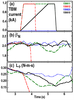
Figure 13. Evolution of (a) the TBM coil current, (b)  , and (c)
  in low-torque discharges for three TBM field settings: no TBM field (dotted blue), uncorrected TBM field (dash–dot red), and compensated TBM field (dashed green and solid black traces). In every discharge, a 5/4 NTM is present when the TBM coils are energized. Onset of a 4/3 NTM instability in 159 811 (green) at 4390 ms reduces energy and particle confinement, and modifies the torque balance.
Download figure:
Standard image High-resolution imageAlthough n = 1 EFC avoids loss of the H-mode, equilibrium changes due to the TBM field can modify tearing mode stability and the background plasma equilibrium. This is observed in a pair of discharges where the ramp rate of the TBM and n = 1 compensation fields was varied. In discharge 159 810 (figure 13, black traces), fields are ramped at a rate of 0.65 kA s−1 with a m/n = 5/4 NTM present. In this case, the applied 3D field torque slows the plasma rotation and NTM frequency. The thermal energy confinement time ( ) is reduced from the pre-TBM level of 167 ± 8 ms down to 151 ms and
  is reduced by a few per cent. In a repeat discharge (159 811), the TBM current is increased to 1.1 kA in 0.2 s resulting in a more rapid decrease in rotation. At 4.39 s, a 4/3 NTM is observed to grow replacing the 5/4 mode at the same phase velocity (figure 14). Analysis of magnetic fluctuations measured using toroidal and poloidal arrays of Mirnov probes, as shown in figure 1, follows the time-series modeling described by Olofsson et al [24]. This larger-amplitude NTM further reduces
  to 142 ms and
  by ∼10% (figure 13b). The plasma rotation increases following the mode onset (figure 13c), due mainly to a reduction in the density profile at constant input torque. If not for this equilibrium change, one would expect that a larger NTM, located closer to the vacuum vessel wall would decrease the plasma rotation, since it is positioned closer to the vacuum vessel wall. These observations highlight some of the challenges associated with predicting TBM effects in ITER, and suggest that an accurate assessment must account for the impact of changes in the NTM stability.
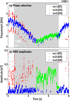
Figure 14. (a) Phase velocity and (b) root-mean-square (RMS) amplitude of fluctuations in the poloidal magnetic field in discharge 159 811 observed with toroidal and poloidal arrays of magnetic sensors. TBM and associated n = 1 compensation fields are applied in the shaded region. The n = 1 activity (red circles) is associated with the sawtooth precursor. The phase velocity (frequency divided by toroidal mode number) of the low-amplitude m/n = 5/4 NTM (blue circles) decreases after the TBM is energized. After 4.39 s, a larger-amplitude 4/3 NTM (green circles) becomes unstable replacing the 5/4 mode and leading to an increase in the plasma rotation frequency.
Download figure:
Standard image High-resolution image5.1. Margin for stable operation with TBM fields
Since n = 1 EFC does not obviate the TBM torque, it is important to understand the margin for stable operation in the space of applied torque, TBM field and the accuracy of EFC. These dependences are studied using two different experimental methods. In the first, an uncorrected TBM field is ramped up at fixed NBI torque to identify the critical TBM current for triggering a locked mode. In the second, a fixed compensated TBM field is applied and the NBI torque is ramped down to identify the minimum accessible torque prior to onset of the locked mode. Note that the second method only addresses the issue of access to low torque; it does not demonstrate sustained stable operation at the achieved torque level. Until reproducible conditions can be achieved below 1 Nm, it is not meaningful to assess TBM effects in that regime.
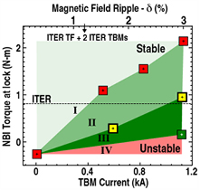
Without compensation, the TBM field progressively reduces low-torque access to levels above the ITER equivalent torque (figure 15, red points). Assuming the most unfavorable extrapolation to ITER where TBM effects in DIII-D and ITER are the same [5], these results imply the ITER Q = 10 scenario will not be accessible with uncompensated TBM fields. However, with empirically optimized n = 1 EFC, operation even below the ITER equivalent torque is achievable (transiently) at nearly three times the ITER equivalent field ripple (green point). (Recall from section 5.1 that sustained operation at 3% ripple is possible at 1.1 Nm.) With partial compensation, stability is lost near the ITER level if the TBM compensation field is reduced by 50% (yellow points). A nearly linear scaling with TBM field is found for two subsets of the data: uncorrected and partial compensation. Taken together, these results demonstrate that compensation of n = 1 harmonics of the TBM field is essential to access the expected values of applied torque in ITER. Furthermore, they show that predictions of the optimal compensation currents must have an error that is less than 50% in order to provide access to ITER equivalent torque values without the need for empirical optimization.
Figure 15. Torque access as a function of TBM field strength expressed in terms of TBM coil current and total magnetic field ripple for combinations of TBM and TBM-compensated fields: no n = 1 EFC (red), with optimal n = 1 EFC (green) and with partial n = 1 EFC (yellow). Region I can be accessed without encountering an n = 1 locked mode. Regions II and III are stable only with EFC and inaccessible otherwise. Region IV cannot be accessed even with optimized EFC of the TBM field. The dashed line marks the expected ITER-equivalent torque level in DIII-D. The total field ripple expected from a pair of 1.3 ton TBMs in ITER together with the TF ripple is 1.2%.
Download figure:
Standard image High-resolution image
6. Summary and discussion
Recent DIII-D experiments demonstrate that TBM error fields limit low-torque access in the ITER Q = 10 operational scenario. The low-torque TBM field limit depends on the applied torque and is set by the onset of n = 1 locked modes, which lead to disruption of the plasma current. Fortunately, the locked mode limit can be avoided using only n = 1 compensation fields generated by ex-vessel control coils similar to the single-row equatorial correction coils planned for ITER. With empirically optimized compensation fields, sustained operation at ITER performance metrics is possible at three times the ITER equivalent toroidal magnetic field ripple for a pair of TBMs in one equatorial port.
Variations in the accuracy of the EFC indicate that a reduction of 50% in the compensation field away from the empirically optimized control field results in an error field threshold that is just above the ITER-equivalent torque in DIII-D. This result sets the required accuracy (less than 50% error) for both predictions of the optimal compensation currents and the accuracy of empirical error field optimization methods. Comparisons between the empirically optimized compensation currents and IPEC–PENT modeling show that existing models do not accurately predict the compensation current to better than 50%, which implies that, without improved theoretical understanding, empirical methods will be needed to develop TBM EFC algorithms in ITER.
Although TBM field compensation is found to be essential at low torque in the ITER scenario, sustained operation with TBM fields can be achieved with resources expected to be available in ITER using the same experimental techniques discussed here. Even so, it is important to note a number of key issues that affect the extrapolation of DIII-D results to ITER.
First, even though the techniques used here do not rely on the onset of disruption for identifying optimal compensation currents (as done in seminal error field studies on DIII-D [32, 33] and low-density L-mode discharges with mock TBM fields [5]), these techniques are not inherently disruption-free at low applied torque. Disruptions were encountered when applying compensation currents far from the optimal EFC settings. Since the gradient of the rotation with respect to the coil currents is relatively weak near the optimal currents, it is desirable to obtain data at extreme values to constrain the fits. Therefore, if the plasma rotation is the main figure of merit for optimizing compensation fields, some techniques to avoid and/or mitigate disruptions may be needed when optimizing the compensation field at high plasma current. Real-time error field optimization techniques able to identify and track optimal EFC currents without triggering instabilities would also be highly desirable.
Second, it should be noted that the ITER-like plasmas in DIII-D were operated at high collisionality, in which neoclassical toroidal viscosity is reduced, so the margin in compensation requirements discussed in section 5.1 provides encouragement, but no proof that the ITER Q = 10 scenario will be accessible with TBMs installed. However, the results do give increased confidence that TBM error field algorithms can first be developed at high collisionality in ITER. If the plasma response to the applied TBM field is modified at low collisionality, real-time optimization techniques capable of tracking a time-dependent error field source, or plasma response, would probably prove to be a very useful tool in the development of low-collisionality plasma scenarios.
Since high- plasma operation provides an attractive possible path to improved performance in ITER, and since TBM effects on plasma confinement scale with
  , recent TBM experiments at high plasma pressure were pursued to evaluate the impact of EFC and establish if n = 1 field amplification is playing a role to enhance TBM effects. In these studies, uncorrected TBM fields degrade energy confinement and the plasma angular momentum, but do not trigger a disruption owing to increased levels of applied torque. However, as the torque is reduced, locked modes are encountered even at torque levels greater than 4 N m. This confirms that the unperturbed rotation level is immaterial in the onset of the locked mode; plasmas at any rotation are potentially susceptible to rotation collapse if the magnitude of the error field and the level of rotation braking are sufficient to trigger a locked mode. Therefore, a critical capability for support of ITER operation at high plasma current will be the ability to accurately predict the resonant field and associated torque from applied TBM fields. Only with such a validated quantitative model, accurate predictions of the ITER rotation profile and error field penetration threshold scalings that incorporate plasma rotation, will it be possible to assess the expected field level in ITER and accurately predict to what extent TBM fields will limit the operational space. This capability would be extremely valuable for planning the experiments that will develop EFC of TBM fields in ITER, especially because ITER will have little capability to vary the injected torque owing to the available input power, and thresholds for H-mode access.
In these discharges, n = 1 EFC leads to recovery of a dominant fraction of the TBM-induced plasma pressure and rotation degradation. Both single-row ex-vessel and two-row in-vessel coils perform well despite improved coupling between the in-vessel coil and the dominant global plasma instabilities. These results further validate concepts of a dominant mode to the n = 1 plasma response using an error field with a broad toroidal spectrum, thereby extending recent studies using n = 1 error fields [30]. One implication is that compensation currents can be mapped from one coil set to another using the coupling to the dominant mode as a figure of merit as demonstrated here for intrinsic EFC in section 3.2. This approach may be useful in ITER if it proves impractical to optimize compensation fields using the superconducting ex-vessel correction coils. These results also highlight the importance of nulling coupling between error fields and dominant modes regardless of the plasma scenario (ITER baseline or hybrid), since the plasma response and associated plasma rotation braking are increased whenever global modes are excited. In the ITER baseline, the impact of the plasma response is modified by the reduced plasma rotation, while in the hybrid the plasma response is increased due to increased plasma pressure.
In addition to avoiding severe confinement degradation at high  , EFC provides for a significant reduction of localized heat loads to the first wall, which is coincident with a substantial reduction in the n = 1 plasma response. These results are potentially important for assessments of TBM-induced heat loads in ITER and in the design of the first wall. At present, energetic particle simulations that include the vacuum TBM error field indicate negligible heat loads to the first wall in ITER due to TBM-induced fast ion losses [34]. However, these calculations neglect the plasma response to the TBM error field, which can be the dominant contribution to the total non-axisymmetric magnetic field. Although the correlation between plasma response and a reduction in heat load may be coincidental, these results motivate an assessment of the role of the plasma response on energetic particle losses in the ITER configuration with TBM fields. Such a study is also motivated by recent fast ion loss experiments in DIII-D involving error fields with a single toroidal harmonic; these show the predicted magnitude of the energetic particle loss fraction of fast ions from the edge of H-mode plasmas depends significantly on the model of the perturbed magnetic field [35]. In particular, further studies focusing on the role of rotation and kinetic effects on the plasma response would be relevant.
In closing, the results presented here provide great encouragement for the viability of the ITER TBM program. The recent experiments address important TBM-related questions in two challenging plasma regimes: high normalized current at low applied torque and high-beta operation. In both cases, n = 1 EFC alone avoids potentially detrimental TBM effects, regaining good confinement and providing protection against high heat flux to the first wall. Although an extrapolation of the DIII-D results to the ITER configuration remains to be completed, these results suggest the proposed limits on the amount of ferromagnetic material permitted in each TBM are reasonable, and increase our confidence that ITER will be able to achieve its scientific mission while developing critical blanket technology for DEMO.
Acknowledgments
The authors express their appreciation to many members of the DIII-D operations staff for their support during the 2014 TBM campaign including Arnie Kellman, Edward Allen and Richard Lee. We also acknowledge substantial effort by Rejean Boivin, Armando Chavez and Anthony Horton during the re-installation of the TBM and TBM-related diagnostics. This material is based upon work supported in part by the U.S. Department of Energy, Office of Science, Office of Fusion Energy Sciences, using the DIII-D National Fusion Facility, a DOE Office of Science user facility, under awards DE-FC02-04ER54698, DE-AC05-00OR22725, DE-AC02-09CH11466, SC-G903402 and DE-FG02-04ER54761. DIII-D data shown in this paper can be obtained in digital format by following the links at https://fusion.gat.com/global/D3D_DMP. The views and opinions expressed herein do not necessarily reflect those of the ITER Organization. ITER is a Nuclear Facility INB-174.
Footnotes
- 8
ITER will also have a 'top' and 'bottom' ex-vessel coil.
- 9
ITER will also have a third in-vessel coil array at the midplane.