


Abstract
The ITER Neutral Beam Test Facility (NBTF), called PRIMA (Padova Research on ITER Megavolt Accelerator), is hosted in Padova, Italy and includes two experiments: MITICA, the full-scale prototype of the ITER heating neutral beam injector, and SPIDER, the full-size radio frequency negative-ions source. The NBTF realization and the exploitation of SPIDER and MITICA have been recognized as necessary to make the future operation of the ITER heating neutral beam injectors efficient and reliable, fundamental to the achievement of thermonuclear-relevant plasma parameters in ITER. This paper reports on design and R&D carried out to construct PRIMA, SPIDER and MITICA, and highlights the huge progress made in just a few years, from the signature of the agreement for the NBTF realization in 2011, up to now—when the buildings and relevant infrastructures have been completed, SPIDER is entering the integrated commissioning phase and the procurements of several MITICA components are at a well advanced stage.
Export citation and abstract BibTeX RIS

Original content from this work may be used under the terms of the Creative Commons Attribution 3.0 licence. Any further distribution of this work must maintain attribution to the author(s) and the title of the work, journal citation and DOI.
1. Introduction
Efficient and reliable operation of the Heating Neutral Beam Injectors (HNB) [1] is required to achieve thermonuclear-relevant plasma parameters in ITER, a fundamental step on the path towards unlimited sources of clean fusion energy. ITER will be provided with two HNBs, each one expected to inject into the plasma a beam composed of deuterium atoms accelerated up to 1 MeV energy, delivering a power of up to 16.5 MW for a beam pulse length up to 3600 s [2].
Since these operating conditions have never been reached jointly before, it was recognized that a dedicated Neutral Beam Test Facility (NBTF) is needed to carry out an international R&D programme aimed at constructing, testing and optimizing the full-scale prototype of the HNBs and at assisting ITER during its operation [3, 4].
The ITER NBTF, called PRIMA (Padova Research on ITER Megavolt Accelerator), is hosted in Padova, Italy (figure 1). It includes two experiments: MITICA, the full-scale prototype of the ITER HNB injector and SPIDER, the full-size radio frequency (RF) negative-ion source. Very significant progress has been achieved in the construction of MITICA and SPIDER [5, 6].

Figure 1. 3D CAD view of the PRIMA facility.
Download figure:
Standard image High-resolution imageThe ITER NBTF is being realized mainly through the contribution of Consorzio RFX, of the European, Japanese and Indian Domestic Agencies (Fusion for Energy—F4E, JADA, and INDA, respectively), with the support of the ITER Organization and the collaboration of several European laboratories, including IPP-Garching, KIT-Karlsruhe, CCFE-Culham, and CEA-Cadarache. The schedule of the NBTF construction and experiments is strictly aligned with the general timeline of the ITER tokamak experiments, so as to guarantee that sufficient experience on the operation of the prototype source (SPIDER) and of the full injector (MITICA) will be available before starting the construction of the HNBs for ITER. According to the official ITER schedule, the first plasma will be achieved in 2025 and the start of the deuterium–tritium phase, requiring the HNB injectors in operation, will take place in 2031. Therefore, several years will be available to exploit the SPIDER mission to prove the possibility of achieving the ITER HNBs target requirements in an ion source of the same characteristics and size. Similar considerations also apply to MITICA, which is mainly devoted to optimizing the Beam Source—including the 1 MV accelerator—and the Beam Line Components, and will come into operation in 2021. Both experiments shall provide confirmations and key information before the construction of the corresponding components of the ITER HNBs. Both SPIDER and MITICA are also aimed at improving the HNBs performance in terms of reliability and availability, thus significantly contributing to risk mitigation for the successful operation in ITER.
This paper mainly reports on the design, developments and R&D that have been carried out to realize the ITER NBTF and the relevant projects SPIDER and MITICA, and highlights the huge progress made in few years since the signature of the agreement for the NBTF in 2011.
2. SPIDER
The risk mitigation strategy for the ITER HNBs involves the early assessment of beam extraction from an RF driven ion source having the same dimensions and characteristics as for the ITER HNBs. This is SPIDER, a negative ion source based on the concept developed at IPP-Garching [7, 8]. The challenging target parameters are summarized in table 1. For the achievement of this performance, a common international effort is being dedicated, in close collaboration mainly with IPP-Garching, where the half ITER-size ELISE test facility is in operation [9]. SPIDER has the same size as the ITER HNB ion sources and the same extractor design. It provides extraction and acceleration of H− and D− up to 100 keV for a pulse duration up to 3600 s. It also features ITER-like filter field configuration and caesium oven layout and environment (the caesium ovens are entirely in vacuum along with the whole beam source). Moreover, a wide set of diagnostics supports beam characterization and design validation for components. This is necessary for adjustments and optimizations during operation, aiming to fulfil the SPIDER mission to optimize the negative ion source performance for the ITER HNBs. The results of the SPIDER experiment will be also relevant for the ITER Diagnostic NBI equipped with a beam source expected to operate at 100 kV, 60 A, for one hour [10]. A view of the SPIDER in-vessel components is shown in figure 2, and an overall view of SPIDER in figure 3.
Table 1. SPIDER requirements.
| Unit | H | D | |
|---|---|---|---|
| Beam energy | keV | 100 | 100 |
| Max beam source filling pressure | Pa | 0.3 | 0.3 |
| Max deviation from uniformity | % | ±10 | ±10 |
| Current density of ions extracted from the plasma | A m−2 | >355 | >285 |
| Beam on time | s | 3600 | 3600 |
| Co-extracted electron fraction (e−/H−) and (e−/D−) | <0.5 | <1 |
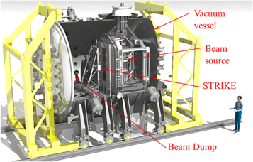
Figure 2. SPIDER view with in-vessel components.
Download figure:
Standard image High-resolution image
Figure 3. View of the SPIDER vacuum vessel during vacuum tests at the PRIMA site.
Download figure:
Standard image High-resolution image2.1. SPIDER vacuum vessel
The SPIDER Vacuum Vessel (VV) is an AISI 304 L stainless steel cylindrical vessel having diameter of 4 m and an overall length of about 6 m (see figure 3). It is made of two separate and demountable modules and two end lids, each of them installed on rails to facilitate the assembly and the opening/closing movements for future maintenance. Manufacture of the VV required optimized welding processes, very accurate machining, surface preparation and intermediate tests at the factory to fulfil the requirements for vacuum tightness, vacuum compatibility, precise positioning and opening/closing operations [11]. The VV is provided with three 100 kV ceramic bushings for service line feedthroughs: one for electrical connections (power and signal) and two for hydraulic and gas injection pipes. Figure 4(a) shows the two hydraulic bushings placed on the bottom of the VV. The successful results of the high voltage (HV) electrical tests are shown in figure 4(b): the target value of 130 kV was sustained for one hour at a vacuum level of 3 × 10⁻⁷ mbar, after about four hours of conditioning at increasing voltage levels.
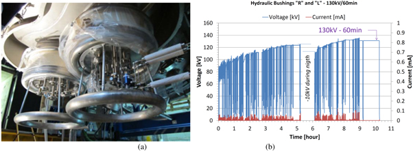
Figure 4. (a) Assembled hydraulic bushings on the SPIDER vacuum vessel. (b) Results of the HV insulation tests on site.
Download figure:
Standard image High-resolution imageThe vessel is presently fully assembled and tested, positioned inside the neutron shield and connected to the HV transmission line and to the vacuum and gas injection equipment.
2.2. SPIDER beam source
The SPIDER Beam Source (BS) [12], the most complex part of the device, is designed to accelerate the required negative ion beam up to 100 keV. The RF driven negative ion source, consisting of plasma source and extractor, is topologically identical to the existing one in ELISE and those to be provided for MITICA and ITER.
The plasma is generated inside eight small cylindrical chambers called drivers, where gas (hydrogen or deuterium) is injected at a pressure of about 0.3 Pa and ionized by RF power transferred from coils wound around the drivers. RF matching network components and vacuum capacitors are installed on the rear side of the ion source. Plasma diffuses into an expansion chamber towards the plasma grid (PG); this grid is covered with a thin layer of caesium, which lowers the work function so that the impinging hydrogen/deuterium atoms are more easily turned into negative ions. A bias plate (BP), divided into five segments, is mounted 10 mm upstream of the PG, with adjustable potential, in order to absorb a variable amount of electrons and thus to modify and optimize the electric field distribution in the region of negative ion production for eventual maximization of the performance.
A suitable voltage is applied between the PG and the following extraction grid (EG) so that the negatively charged beams are extracted from the plasma through the apertures located in the PG by applying an extraction voltage with respect to the following extraction grid (EG) so as to keep perveance matching. The grids, with the same geometry as the ITER ones, about 2 m2 wide, are provided with 1280 apertures, corresponding to the beamlets constituting the overall beam. Electrons are unavoidably co-extracted along with the negative ions, and are dumped onto the EG by a suitable arrangement of permanent magnets located in the EG. The negative ions are subjected to a further voltage, between the EG and the grounded grid (GG), so that they are accelerated to full energy.
The design of the accelerator for SPIDER [13] was aimed at obtaining the best beamlet optics by an integrated approach, taking into consideration at the same time physics and engineering aspects. The aperture shape and the distances between the grids were optimized, and suitable protrusions of the grids (called kerbs) were adopted; moreover, the apertures were arranged to steer the beamlets and to counteract electrostatic repulsion among neighbouring beamlets.
Some novel concepts were included in the design: the magnetic filter field, dedicated to reducing the amount and the temperature of electrons in the plasma just before the PG, is generated by a current flowing inside the PG itself, unlike the usual realizations adopting permanent magnets [14], and the current return path is such that only a low residual magnetic field penetrates into the RF drivers. The magnetic field that dumps the electrons onto the EG affects also the trajectories of negative ions; such a deflection is compensated for by a second array of permanent magnets housed in the GG and by a ferromagnetic plate just after the GG. The background gas distribution was considered in the accelerator design optimization [15].
R&D activities were performed in support of the design: a novel concept has been developed with regard to heterogeneous joints, resulting in a patent registered as the Vacuum Tight Threaded Junction (VTTJ) technique [16, 17], and an Insulation and Cooling Experiment (ICE) testing facility has been established to test the specific small cooling ducts embedded in the thickness of the actively cooled copper components, characterizing single channels and complete parts of grids [18–20].
The procurement of the SPIDER beam source is currently ongoing: manufacturing of the most critical parts is completed, including the overall support structure and the large plates for accelerator and ion source. The assembly in factory is in progress, and the delivery is expected in June 2017 [21]. Photographs of the SPIDER BS partially assembled inside the supplier's assembly room are shown in figure 5.

Figure 5. SPIDER BS under assembly at the supplier's factory: ion source plasma chamber (a) and support structure (b).
Download figure:
Standard image High-resolution image2.3. SPIDER calorimeters and diagnostics
The wide set of SPIDER diagnostics [22], together with the numerical codes to analyse the experimental results, are expected to provide design validation and help in operation optimization [23]. Table 2 lists the source and beam diagnostics with measured parameters: it is a wide-range set because it is crucial to get as much as possible information to demonstrate achievement of the challenging target performance in terms of beam intensity, ratio between co-extracted electrons and negative ions, uniformity and divergence over the beam profile for pulses up to one hour in duration.
Table 2. SPIDER diagnostics.
| Source Diagnostics | Beam Diagnostics |
|---|---|
| Electrical currents (current balance at power supplies) | Calorimetry and surface thermocouples (beam uniformity, divergence, aiming) |
| Calorimetry and surface thermocouples (power load on source components; detailed layout of thermocouples given in [12, 25]) | Instrumented calorimeter STRIKE (beam uniformity over 2D profile and divergence, resolution 2 mm < 10 s beam pulse) |
| Electrostatic probes (plasma uniformity, Te, ne) | Beam emission spectroscopy (BES) (beam divergence & uniformity, stripping losses) |
| Source optical emission spectroscopy (Te, ne, nH−, nCs, nH, impurities) | Beam tomography (beam uniformity over 2D profile, resolution 1/4 beamlet group) |
| CRDS (nH−), Laser absorption (nCs) | Neutron imaging (beam uniformity horiz. profile, resolution 3–4 cm, D only) |
SPIDER is the ideal test stand, having the same characteristics and size as the ITER ion source, but being much more accessible to experiments; conversely, diagnostics mounted on the ITER HNBs will be essentially limited to thermocouples, due to neutron and gamma radiation and to the limited number of access ports. Experimental data obtained from SPIDER operation have the potential to validate the physics models underlying both the source and the beam. Furthermore, the same data can be used to assess what information can be obtained from the limited set of measurements available in the ITER HNBs.
SPIDER is provided with two calorimeters: the water-cooled Beam Dump (BD) and a high-spatial-resolution uncooled calorimeter called STRIKE. The BD allows the maximum power of 6 MW to be absorbed and removed in steady state condition. It is procured by INDA, and was delivered at the PRIMA site in 2015 [24]; figure 6 shows the BD positioned inside the experimental hall at PRIMA site for the installation of thermocouples (TC). The BD is made of two panels arranged in 60-degree V shape, leading to a 30-degree beam incidence angle. Each panel consists of 31 water-cooled hypervapotrons (HPV), vertically stacked, and is cooled by an independent cooling circuit. The BD is equipped with TCs to study the power balance and the beam uniformity at relatively low resolution [25]. A TC is fastened to the outlet pipe of each HPV and to the input and output manifolds, thus measuring two power deposition vertical profiles, one for each panel. Additional 112 TCs are inserted at 3 mm from the beam heated surface of the central HPV of each beamlet group, to characterize with smaller thermal inertia both the vertical and horizontal power distribution of the beam. Simulations show that beamlet groups with 3 and 7 mrad divergence are clearly distinguishable, and information on divergence and horizontal aiming can be retrieved from the slope and position of edge gradients of horizontal thermal profiles [26]. In addition, the two panels of the BD are electrically insulated from each other and from the vacuum vessel: each panel is grounded outside the vacuum chamber and the measurement of the return current allows calculation of the total beam current hitting each panel, thus complementing the calorimetric measurement in the estimate of the power balance.
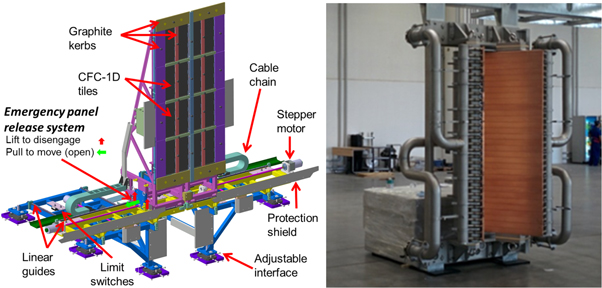
Figure 6. CAD view of STRIKE (left). BD as presently stored inside the experimental hall (right).
Download figure:
Standard image High-resolution imageSTRIKE—see figure 6—is a high resolution, short pulse calorimeter, based on unidirectional carbon fiber composite (CFC) tiles, whose development has required accurate R&D [27]. STRIKE is made of 16 1D CFC tiles, which are arranged in two panels perpendicular to the beam and intercepts the whole beam. The 20-fold higher thermal conductivity normal to the tile surface allows the precise reproduction of the front heated surface on the reverse, whose temperature map can be recorded by two infrared cameras. Since the tiles are not actively cooled, STRIKE can operate only with pulses having a duration of a few seconds; for longer pulses, the panels, installed on a remotely controlled support system operating under vacuum, are moved laterally out of the beam, which is then intercepted by the BD. STRIKE is the main beam diagnostic in SPIDER, as it is expected to achieve the spatial resolution of 2 mm over the entire beam profile, thus validating all other systems, especially those based on line-of-sight integrated measurements like beam emission spectroscopy and tomography. Beside beam uniformity, STRIKE can measure its divergence, by positioning the tiles at different distances from the source exit, and the collected beam current, as tiles are insulated from their support and are biased.
STRIKE will be ready to operate on SPIDER during the first phase of experiments. Other diagnostics that are required at the beginning of SPIDER operation (thermocouples, emission and laser spectroscopy, electrostatic probes, visible and infrared (IR) imaging) are almost ready including vacuum windows and the integration with the data acquisition system, while other ones still need R&D to be completed [28]. Prototypes, like tomography cameras, and full setups from sensor to acquisition system, basic analysis and visualization software codes, like those for thermocouples and IR cameras, are being tested at the NIO1 RF source test facility in operation at Consorzio RFX in Padova [29].
2.4. SPIDER caesium ovens
SPIDER will be equipped with three caesium (Cs) ovens to inject fresh caesium into the beam source in a controlled way. A dedicated R&D program [30] has been planned since the design is complicated by the vacuum environment, the high reactivity of caesium, the difficulty of controlling the temperature distribution among the parts and maintaining its stability, the need to develop a special customized solenoid valve in vacuum. The first oven prototype is ready to be tested on a caesium test facility at the PRIMA site; the three ovens are expected to be installed on the SPIDER beam source by the end of 2017. In parallel, the caesium oven test facility being established at the PRIMA site (section 4.6) will allow development and optimization of this component, crucial for the source performance.A section view of a typical caesium oven for the SPIDER Beam Source is shown in figure 7.
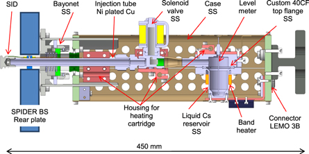
Figure 7. Section view of a typical caesium oven for the SPIDER BS.
Download figure:
Standard image High-resolution image2.5. SPIDER power supply system
The basic design approach of the SPIDER Power Supply (PS) system derives from one developed for MITICA and ITER HNB [31]. The SPIDER PS includes the Ion Source and Extraction Power Supply (ISEPS), a heterogeneous system of power supplies [32], and the Acceleration Grid Power Supply (AGPS). As the ion source operates at −100 kV to ground, ISEPS is situated in a large Faraday cage (13 m (L) × 11 m (W) × 5 m (H)), called the High Voltage Deck (HVD) according to the selected overall design approach. HVD is mounted on supporting insulators and clad with a conductive metal sheet to reduce the electromagnetic interference (EMI) [33]. Table 3 reports the main rating data of ISEPS and AGPS; the AGPS is procured by INDA, all the other SPIDER PSs and all the other plant systems necessary to operate SPIDER are procured by F4E.
Table 3. ISEPS and AGPS main output data ratings.
| ISEPS | |
|---|---|
| Extraction (EGPS) | −12.8 kV across 6 mm gap, 140 A |
| Radio frequency (RFPS) | 4 units, 200 kW each f = 1 MHz, 50 load |
| Bias (BPS) | ±30 V, 600 A |
| PG filter (PGFPS) | 15 V, 5 kA |
| AGPS | −96 kV DC across 35 mm gap, 71 A DC |
The final acceptance tests of ISEPS were successfully completed in September 2016, after the execution of a wide-range test program including tests on individual power supplies and a set of special tests whose goal was to check the integration of the ISEPS subsystems under the operational conditions foreseen in SPIDER. In figure 8(a) the ISEPS system in the final installation conditions is shown, after completion of the tests.

Figure 8. (a) The ISEPS system in the final installation condition inside the HVD. (b) AGPS switching modules.
Download figure:
Standard image High-resolution imageThe AGPS system is a power supply rated for 96 kV/71A; it is based on pulse step modulation technology and includes three oil-insulated multi-secondary transformers and 150 switching modules. The installation is presently well advanced, as can be seen in figure 8(b).
The power and signal connections from ISEPS and AGPS to the ion source are realized by means of a high voltage transmission line (TL), conceived as an original air insulated tri-axial line, consisting of a large (0.5 m diameter) HV inner conductor, inside a double screened structure (1.2 m × 1.2 m) shown in figure 9(a) that is aimed at assuring sufficient protection from electromagnetic interference (EMI) [34].

Figure 9. (a) View of the installed TL with the outer conductor in evidence. (b) TL interface with the VV, (c) Time history of applied voltage during conditioning and acceptance tests.
Download figure:
Standard image High-resolution imageThe TL interface with the SPIDER vacuum vessel is shown in figure 9(b); each TL cable/conductor is connected to its corresponding feedthrough, embedded on the metallic flange of the ion source electric bushing. The site acceptance tests were concluded by mid-2016; the most challenging one was the main insulation test in the final installation condition, with the ISEPS equipment inside the HVD and the vessel in vacuum. The test itself consisted of the application for 3 h of −120 kV DC between HVD (internally connected to the high voltage screen) and ground (to which the TL outer conductor was connected). The test was preceded by a preliminary gradual voltage application lasting many hours to condition the vacuum insulation inside the vessel and to reach stable voltage conditions at the TL test voltage level.
2.6. SPIDER instrumentation and control
The SPIDER Instrumentation and Control (I&C) system is implemented in three vertical tiers: conventional control (CODAS, Control and Data Acquisition System) [35], plant-wide investment protection (Central Interlock) [36] and Safety systems. These three tiers are not required to comply with the ITER Plant Control Design Handbook as SPIDER is not an ITER plant system. Nevertheless, most hardware/software technologies prescribed by ITER for the implementation of plant system I&C have been prototyped, tested and finally used [37]. SPIDER CODAS integrates three software frameworks: EPICS [38], MDSplus [39], and MARTe [40], and much effort has been devoted to encompassing them into a single, flexible and reliable software environment [41]. The scopes of these three software frameworks do not overlap significantly: EPICS is aimed at system supervision (about 20 plant systems are monitored), MDSplus at data management (130 Mbyte s−1 data throughput, 50 TByte/year estimated annual data storage in normal operation), and MARTe at fast, real-time control (500 μs fast control cycle time). The SPIDER Central Interlock system has been designed to protect the investment, starting from an accurate analysis of the failure modes (failure mode and effect analysis). Slow and fast protection functions have been identified, characterized and implemented. As for the time constraints, slow plc-based protection actions are required to be implemented in 20 ms reaction time (from fault input detection to protective output generation), whereas fast interlock (National Instruments CRIO based) protection actions require a reaction time of less than 10 μs, mainly to protect the electric systems during breakdown and beam-off events. The SPIDER safety system is under development and will be based on a redundant, PLC-based architecture.
SPIDER CODAS and Interlock systems have been procured, installed and tested; an I&C cubicle hosting the SPIDER CODAS interface with SPIDER ISEPS and AGPS is shown in figure 10(a); on the right side, one panel of the human–machine interface of the SPIDER gas and vacuum system. The integrated commissioning between control and plant systems is being started; the exchange of thousands of digital and analogue signals and commands are being verified and operational sequences and fault conditions are being tested.

Figure 10. SPIDER Plant System CODAS—(a) Power Supply Plant System I&C—SPIDER CODAS interface with SPIDER ISEPS and AGPS. (b) One panel of the human–machine interface of the SPIDER gas and vacuum system.
Download figure:
Standard image High-resolution image2.7. SPIDER integrated commissioning and first operational plan
Over the past few years, thorough studies regarding worker safety and occupational radiation protection from radiological agents (mainly secondary neutrons) have been completed for SPIDER. License for using radiation sources and conducting a radiation practice was issued by the Italian competent authorities in July 2016. As of January 2017, detailed prescriptions are being implemented to improve the safety procedures as required by the licensing authorities. Operation will become possible in the short term.
The SPIDER integrated commissioning and first operational plan is described in [42]. The integrated commissioning will be performed after the individual plant systems are operational, and will follow a staged approach, associating the test parameters of the plant systems in each commissioning phase with the values required for the following operational phase. The integrated commissioning will regard the operation of RF drivers, magnetic filter field, power supplies (including extraction and accelerator). The tests will be performed in air (for larger measurement capability of voltages and currents), in vacuum (high voltage conditioning of the accelerator) and with hydrogen (characterization of voltage holding).
The early SPIDER operation will feature the following phases:
- characterization of plasma ignition and ion source operation, without caesium and at low RF power; during this phase, the influence of the filter field on plasma ignition and the ion source uniformity will be assessed; the dependence of plasma parameters and plasma drifts on filter field PG bias and source gas pressure will be investigated;
- extraction and acceleration of a beam without caesium (low current density): the design of the accelerator will be validated; beam deflection and divergence will be assessed, as well as the amount of co-extracted electrons, the influence of PG bias and filter field, and the compensation of the zigzag pattern due to the permanent magnets located in the EG;
- evaporation of caesium and extraction and acceleration of a beam: the ion source plasma and the beam will be characterized, and first optimizations in terms of beam uniformity and co-extracted electrons will be performed.
Experiments will be mostly run in hydrogen, but some first verifications of the isotopic effect with deuterium will be carried out. Then the RF power will be raised, and investigations performed for increasing beam parameters.
3. MITICA
The construction of MITICA, which is the full-scale prototype of the ITER HNBs, entails a large step forward in terms of power and energy output with respect to the neutral beam injectors operating in the existing tokamaks. For this reason, MITICA will also necessarily represent a testbed, where the solutions to all the issues related to the achievement of full performance in the HNBs for ITER are to be verified and optimized. MITICA requirements are summarized in table 4.
Table 4. MITICA requirements.
| Unit | H | D | |
|---|---|---|---|
| Beam energy | keV | 870 | 1000 |
| Acceleration current | A | 46 | 40 |
| Max beam source filling pressure | Pa | 0.3 | 0.3 |
| Max deviation from uniformity | % | ±10 | ±10 |
| Beamlet divergence | mrad | ≤7 | ≤7 |
| Beam on time | s | 3600 | 3600 |
| Co-extracted electron fraction (e−/H−) and (e−/D−) | <0.5 | <1 |
MITICA will take direct advantage of the R&D and design optimization carried out for the SPIDER full-size ion source; hence, it is expected that the main issues specifically related to negative ion source operations are addressed with SPIDER, so that the work on MITICA will be mainly focused on the 1 MeV beam.
From the radiological point of view this device presents a real challenge, due to the high power of its particle beam. At the time of writing, an advanced radiation protection analysis is being finalized, aiming at assessing the source radiation values and optimizing worker safety. The first technical report for the licensing enquiry is almost ready, in which various critical issues are considered and sorted out. Some important safety issues related to radiation protection are: the neutron production, the radio-activation of solids, liquids and gases (like the indoor atmosphere), and the shielding of the main hall—which has a very complicated geometry.
A huge design and optimization effort has been focused on the critical aspects arising in the multi-stage, multi-beamlet negative ion accelerator and neutralizer, when voltage, current, and pulse duration are increased. These aspects should be solved by an integrated approach that can be summarized as follows:
- to improve high voltage holding capability in order to reach the target particle energy (1 MeV);
- to maximize the ion beam current produced (up to 46 A in H− or 40 A in D−), and minimize transmission losses, so as to deliver the target neutral beam power (16.5 MW);
- to minimize the heat loads and thermo-mechanical stresses on all components, to guarantee the required fatigue lifetime.
Additional issues are obviously present, tightly linked to the previous points, among which are:
- characterization of the beam by the calorimeter;
- performance of cryo-pumps to guarantee the proper vacuum conditions inside the VV.
An overall view of the MITICA Injector is shown in figure 11, with the main in-vessel components highlighted: the Beam Source, the Neutralizer, the Residual Ion Dump, the Calorimeter, and the Cryogenic Pumps.

Figure 11. View of the MITICA injector with in-vessel components..
Download figure:
Standard image High-resolution image3.1. The MITICA vacuum vessel
All components of the MITICA injector are contained in a VV with overall dimensions of 15 m × 5 m × 5 m (L × W × H), made of stainless steel AISI 304L. It is composed of two parts, the Beam Source Vessel (BSV), containing the Beam Source, and the Beam Line Vessel (BLV), containing the three beam line components and the cryo-pumps. The two parts are manufactured separately, and will be welded together on site, for transportation reasons. They are presently under construction and assembly at the Supplier's factory; in order to optimize the overall MITICA schedule, activity has been more concentrated so far on the BSV, expected to be delivered and assembled on site very soon. The construction of the BLV is going on in parallel, with lower priority, with the target to be completed by the end of 2017; figure 12 gives a view of the BSV and BLV under assembly at the Supplier's premises.
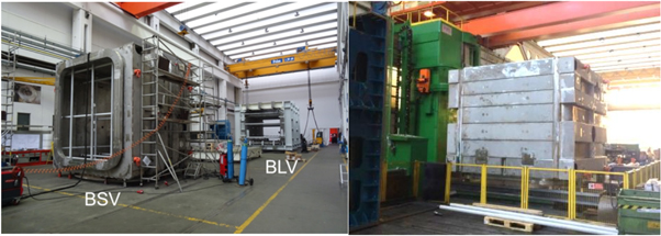
Figure 12. Pictures of the MITICA BSV and BLV during manufacturing.
Download figure:
Standard image High-resolution image3.2. The MITICA beam source
The MITICA/ITER HNB Beam Source (BS) is the key component of the injector, as its goal is the generation of the 1 MeV accelerated beam of deuterium or hydrogen negative ions.
The BS [43] is composed of an RF negative ion source, almost identical to the SPIDER one, for negative ion generation, and a five step electrostatic accelerator with multi aperture grids (MAMuG) for negative ion acceleration; an exploded view highlighting the main components is shown in figure 13.
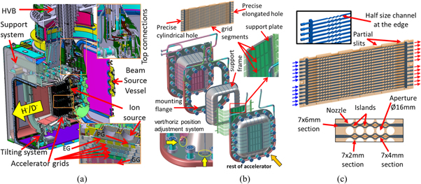
Figure 13. (a) and (b): Exploded view of the MITICA beam source under procurement. (c): Shape of the cooling channels for optimized heat removal.
Download figure:
Standard image High-resolution imageThe RF ion source is kept at an electric potential of about −1000 kV DC to ground for operation with D2 and −870 kV for operation with H2. It is open towards the ion electrostatic accelerator on the front side. An electrostatic shield surrounds the rear side facing the vessel at ground potential.
The negative ions generated in the plasma source are extracted across the gap between the PG and the EG, and accelerated toward the GG across five 200 kV acceleration steps defined by the potential of four intermediate acceleration grids (AG1 to AG4, from −800 kV to −200 kV), thus producing a negative ion beam of 46 A H− (or a 40 A D−).
As in SPIDER, all the grids are approximately 1600 mm high and 800 mm wide, and are divided into four segments of about 400 mm × 800 mm for alignment and manufacturing reasons, with each grid featuring 1280 apertures (320 per segment), grouped in sixteen beamlet groups each made of 16 × 5 apertures. Unlike in SPIDER, aiming requirements, related to the HNB injector configuration in ITER, force the choice of a non-flat configuration among the grid segments, to obtain a converging beam.
During the final design phase, several innovative solutions for the achievement of MITICA full performance have been proposed by Consorzio RFX and adopted [44]. The most significant of these are the following:
- The magnetic field in the accelerator has been optimized for suppressing undesired electrons (both co-extracted and stripped), so effectively reducing the heat loads, and improving accelerator efficiency [45]. A complex system of current-carrying busbars has been conceived to produce a suitable spatial distribution of horizontal component of the magnetic field in the ion source and across the multi-stage accelerator to improve plasma and beam uniformity. In addition, a vertical component of the magnetic field, locally generated by magnet arrays embedded in the acceleration grids, has been conceived so as to maximize the effectiveness of the electron suppression by introducing a diagonal deflection of the electrons.
- New solutions have been developed for the compensation of the undesired deflection of beamlets due to electron-suppression magnetic field [46], resulting in the registration of an international patent registered (Magnetic Grid) [47]. The relevant theory is developed in [48].
- Multi-beamlet optimization of focusing, aiming and compensation of overall beam optics have been achieved by suitable modification of electrode geometries and aperture positions for single-beamlet aiming, also considering assembly tolerances and thermal expansion (beamlets focus at 7.2 m, beamlet groups focus at 24.3 m) [49, 50].
- Optimization of gas pressure profile and grid geometry has been achieved for reducing losses of negative ion current, and mitigating the heat loads on accelerator grids and ion source backplate by secondary particles. The plasma source is operated at a filling pressure of 0.3 Pa to minimize the background gas filling the electrode gaps, where ion-neutral collisions cause loss of negative ion current and generation of back-streaming positive ions and stray electrons at high energy. A detailed calculation of the gas distribution in the beam line and in the beam source was originally performed by Krylov [51]; later the pumping speed in the first grid gap has been maximized by changing the geometry of the grid supports [52]; the distances between grids, and the detailed shape of the beamlet aperture at the electrodes were also optimized [53] and the transverse non uniformity of the effective gas target thickness for stripping was calculated as reported in [54]; finally the operating pressure and pumping speed at the BLV was calculated considering the updated beam line design (see for instance discussion in [55].
- Improvement of heat removal capability on water-cooled grids and reduction of thermo-mechanical stresses on grids and beam line components by geometry optimization [56, 57]. The optimized shape of the cooling channels is shown in the right part of figure 13(c).
- An enhanced design has been developed for high voltage holding capability, by accelerator geometry optimization [58], in relation to the presence of low pressure gas, complex geometrical constraints and magnetic field, single and multiple gaps [59].
All the design aspects of SPIDER and MITICA have been addressed on the basis of extensive numerical simulations. They were carried out using existing numerical codes (commercially available or developed in the high current ion beam community) together with a wide set of dedicated numerical models, specifically developed or improved. The most important features of these models are briefly described in section 4.7.
In several cases, innovative design solutions were proposed, developed and demonstrated at Consorzio RFX by means of specific verification tests. Prototypes of cooling channels for the thermal control of the grid segments have been built separately for each cooling channel geometry, named Single Channel Prototypes (SCP) [60], and for grid segment mockups with up to eight pairs of cooling channels, denoted Multi-Channel Prototypes (MCP) [61]. Flow tests have been carried out in the ICE facility [19].
With specific regard to thermo-mechanical design, it must be highlighted that all internal parts facing charged particles—whether plasma, ions or electrons—are subjected to high heat load, and so require active cooling. In particular, the power deposited on the grids is concentrated on the five acceleration grids (from AG1 to GG), in the range 1.2–1.6 MW each, with a local maximum density in the order of 10 MW m−2, while in the ion source the rear vertical plates are subjected to about 1 MW power deposition by back-streaming positive ions generated in the accelerator by secondary reactions. Several cooling water circuits are foreseen, to actively cool the BS, capable of removing a total power of 10 MW, and guaranteeing accurate temperature control during the pulse. In particular, small cooling ducts are obtained in the thickness of plates by machining and electro-deposition of copper, in order to maximize the efficiency of power removal, with specific optimization developed for MITICA grids [56].
The thermo-mechanical design (see figure 14) must also fulfil several different requirements for the most heated components: not to exceed the maximum temperature of about 200 °C (to keep acceptable mechanical properties of copper), to optimize stress distribution so as to assure a fatigue life (5 × 10⁴ beam on–off cycles) satisfying ITER design standards, and to produce comparable deformations among grids for easier aperture alignment.
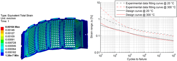
Figure 14. Stress distribution on a grid (left side) and fatigue life of the grids.
Download figure:
Standard image High-resolution imageThe concepts worked out for the assembly and positioning procedures require that each accelerator grid, and in particular each segment of each grid, be positioned with respect to the reference coordinate system identified at the GG center, rather than with respect to the other grids previously assembled. Hence, each grid segment and corresponding supporting plate will be precisely machined and assembled with two calibrated dowels leading the positioning for each segment, in order to guide the free thermal expansion under nominal conditions.
Adjusting elements foreseen between the external flanges and the grid support frames will allow the horizontal/vertical adjustment of each grid, even at the end of the assembly, in order to match the demanding alignment requirements. Moreover, the mechanical supporting system features the possibility of adjusting the source position in the horizontal plane, and tilting it in the vertical.
The design of the BS was completed in 2015 [43]; some critical parts, such as large ceramic post insulators linking the different stages of the accelerator [62], thick Mo coated surfaces protecting rear vertical plates from heat load and sputtering effects caused by impinging backscattered positive ions [63], customized design of RF lines [64], and heterogeneous joints [16], have required significant R&D to verify the feasibility of manufacturing and to qualify in advance unconventional manufacturing processes.
A framework contract for the BS procurement based on a stage-wise strategy has been launched by F4E in 2016; revision of manufacturing procedures is presently in progress, with the aim of finalising them and starting construction—expected to last approximately three years—by mid 2017.
3.3. The MITICA beam line components and diagnostics
The negative ion beam, once accelerated at 1 MeV in D− or 870 keV in H−, after passing through the gas-cell Neutralizer and Electron Dump (NED) and Electrostatic Residual Ion Dump (ERID), produces a ∼17 MW neutral beam, which will be intercepted by a target calorimeter for a duration up to 3600 s (figure 15).

Figure 15. Isometric views of the MITICA beam line components: (a) NED. (b) Calorimeter. (c) ERID .
Download figure:
Standard image High-resolution imageThe neutralizer, operating by charge exchange with gas molecules of the same type, is composed of four channels, with the lateral walls water cooled and capable of absorbing a total power of up to 5 MW. D2 or H2 is injected midway along each neutraliser channel. The neutralization efficiency of the high energy negative ion beam is expected to be about 60%, so a significant amount of positive and negative ions have to be filtered downstream of the neutralizer [65].
This function is performed by the ERID, by applying a transverse electric field. As for the neutralizer, the ERID is composed of five longitudinal panels; between each pair of panels a DC voltage of up to 20 kV is applied, plus, if necessary, an alternating voltage with a trapezoidal waveform of up to ±5 kV. The alternating voltage will sweep the deflected beams along the panels, reducing the average peak power density on the panels. The ERID is designed to absorb and remove a total power of about 19 MW and to withstand power densities of up to 8 MW m−2. Given the high heat loads applied to this component and the resulting thermal stresses, the panels are made of CuCrZr alloy.
The calorimeter consists of two panels in V configuration, whose aim is to absorb the energy of the beam, up to 18 MW. Two large cryo-pumps will also be installed on either side of the BLV. Each cryo-pump has an overall size of 8 m × 2.6 m and features a cryogenic circuit at about 5.5 K (average temperature) cooling cryosorption panels, surrounded by thermal shields kept at around 80 K. The cryo-pumps will be able to ensure a pumping speed of 4700 m3 s−1.
The design of the Beam Line Components: NED, ERID, calorimeter, is complete; thermo-mechanical analyses and fatigue verifications of ERID Beam Stopping Elements has required special care [66, 67]. The procurement tender has been launched with a stage-wise F4E procurement strategy similar to that adopted for the BS. The cryo-pump design is complete too, and the tender phase is being launched. A specific procurement contract was also arranged for 'The design, prototyping and manufacturing of Johnston Couplings for the MITICA cryo-pump and cryo-plant'; these are connection elements between cryo-pumps and cryogenic plant, to be specifically customized for this application.
Even though MITICA will allow much less access than SPIDER, and will be subject to a neutron rate intermediate between SPIDER and ITER HNBs, it is fundamental to equip it with as many diagnostics as possible—in particular, to optimize the operational space of the accelerator and to characterize the beam: the intensity profile, its uniformity and divergence over the profile for pulses of up to one hour in the actual ITER HNB geometry.
The design and development of MITICA diagnostics is in progress. The main system is the large set of thermocouples and optical thermal sensors— about a thousand—installed on all three beam line components, which measure the heat load distribution (from which the beam characteristics can be derived); they are also used for protection purposes [68]. Electrostatic sensors to be installed in the neutralizer and in the ERID have been designed and integrated in the CAD model [69]. A new diagnostic to derive the beam intensity profile at the beam dump, based on the secondary electron emission from the swirl tube panel, has been conceptually developed [70]. Fixing and cable routing of all these embedded sensors has been detailed, to be used for instrumentation installation by the manufacturer of the beam line components (figure 16) [71]. These will likely be the only diagnostics available in the ITER HNB, because they can survive the high neutron flux. In MITICA they will be complemented by other diagnostic techniques: beam emission spectroscopy [72], beam tomography [73] and neutron imaging, analogous to those installed in SPIDER. In particular, for the neutron diagnostic, after completion of the nGEM detector to be installed on SPIDER [74], the model for assessment of diagnostic performance in MITICA has been developed [75], and measurements of the neutron emission rate have been performed in ELISE to investigate the adsorption dynamics of deuterium on the beam dump [76].

Figure 16. CAD model of ERID electrical supply and instrumentation (left) and cross section with details of the standard and ITER-like feedthrough flanges (right).
Download figure:
Standard image High-resolution image3.4. The MITICA power supply system
The complexity of the PS system has been determined by the unprecedented requirements in terms of voltage and power both for the ITER HNB and for MITICA. The issues faced while developing the PS design were related not only to the feasibility of critical parts, but also to the location of the power supply components with respect to the injectors, and to the choice of which parts should be referred to ground potential and which to high potential. The basic choices of the finally selected design approach were to move all the electric and electronic devices far from the neutronic area, thus allowing their full accessibility, and to place the ion source power supplies inside a Faraday cage, named HVD1, air insulated for –1 MV to ground with just one main insulating transformer, operating at 50 Hz. This last choice solved an important feasibility issue related to the implementation of the RF driven Ion Source [31].
Table 5. AGPS voltage and current ratings.
| Stage | Voltage kV | Current A |
|---|---|---|
| DCG1 | 200 | 66 |
| DCG2 | 200 | 64 |
| DCG3 | 200 | 59 |
| DCG4 | 200 | 56 |
| DCG5 | 200 | 54 |
| Total power | 55 MW | |
The ITER HNB/MITICA power supplies include three main systems:
- the Acceleration Grid Power Supply (AGPS) producing the 1 MV DC voltage, in five stages, 200 kV each, to accelerate the Ion Beam. The main characteristics are reported in table 5; the AGPS is divided into a low voltage and a high voltage (HV) section, respectively called AGPS Conversion System (AGPS-CS) [77] and AGPS DC Generator (AGPS-DCG) [78];
- the Ion Source PS to feed the Ion Source, similar to the SPIDER ISEPS;
- the Residual Ion Dump PS feeding the electric panel of the ERID [79].
Figure 17 gives a 3D view of the MITICA Power Supply system; ISEPS and AGPS PSs are connected to the vacuum vessel through a special HV SF6 gas insulated Transmission Line (TL), 100 m long. The TL ends with the HV bushing, part of the primary barrier of the injector, dividing the vacuum environment from the SF6 in the transmission line, with an interspace in dry air [80].
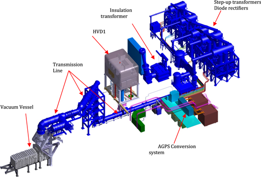
Figure 17. 3D view of the MITICA power supply system.
Download figure:
Standard image High-resolution imageThe grey box in the picture is the HVD1, a unique device consisting of a two-floor metallic box hosting the ISEPS, operating as a Faraday cage, air insulated to ground for −1 MV DC by means of post insulators. The external size of the HVD1 is 12 m × 8 m × 10 m (L × W × H). The post insulators are 6.5 m high. The ISEPS outputs are connected to the TL via an air-to-SF6 gas High Voltage Bushing Assembly (HVBA), installed under the HVD1 [81].
The HV components, in blue in figure 17, including step-up transformers and diode rectifiers of AGPS, TL, HV bushing and the 1 MV insulating transformer of ISEPS [82], are provided by JADA; all the other PS components by F4E.
The procurement of the MITICA PS system is well advanced. The design phase of the F4E procurements: ISEPS, AGPS-CS, HVD1, RIDPS has been closed during 2016; developments were necessary, in particular for AGPS-CS and HVD1, with respect to presently available industrial solutions. Presently, all these procurements are under manufacturing and factory testing phases; an example is given in figure 18 showing the set-up of the long-duration DC voltage withstand test at 1200 kV for 5 h on the 1:5 scaled-down HVD1 mock-up, provided with full-scale post insulators (left side) and the HVBA during assembly for pressure tests.
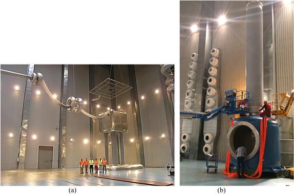
Figure 18. (a) 1:5 HVD1 mock-up inside HSP laboratory for insulation tests. (b) HVBA during assembly for pressure tests.
Download figure:
Standard image High-resolution imageAs for the parts provided by JADA, their delivery on site has started in December 2015 and the installation of 80% of the components has been completed by end of 2016; it has been a very complex activity, requiring preloading of the relevant areas, and special solutions for the alignment of the parts. Figures 19 and 20 report the status of the installation of JADA components, and help in imagining the challenging issues facing a successful assembly.
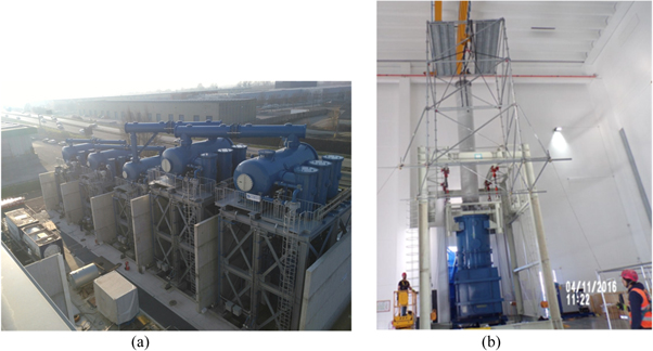
Figure 19. (a) MITICA AGPS: view of external yard with step-up transformers and diode rectifiers under installation. (b) High voltage bushing of the −1 MV insulating transformer.
Download figure:
Standard image High-resolution image
Figure 20. (a) TL in the pit inside the high voltage hall. (b) TL2 vertical section between high voltage hall and experimental hall.
Download figure:
Standard image High-resolution imageAfter the completion of the installation, the individual commissioning and acceptance tests will follow for each system, then the operation of each one under CODAS control will be deeply verified, and finally the testing phase aimed at assessing the integrated operation of the whole PS system on dummy load will start.
Special tests will be designed and executed to verify the whole PS system operation under CODAS control in case of breakdown between the grids, simulated by a special testing device; this is a condition expected to occur rather frequently during a pulse, but extremely hard considering the very high voltage (−1 MV) and power (56 MW), whose delivery has to be interrupted in some tens of microseconds.
Another testing phase expected to be very challenging addresses the verification of the voltage containment in vacuum up to 1MV; special provisions in particular on the HV bushing are under study, also on the basis of the recent experience gained at QST [83].
4. PRIMA: buildings and auxiliary facilities for NBTF
Figure 21 shows a aerial view of the PRIMA buildings. The construction of buildings for NBTF, including auxiliary conventional plants, started in October 2012 and was finished in 2015.The installation of components and plants has proceeded since the end of 2014. Further works have been done in 2016 to complete the Facility, including the MITICA bio-shield made of 1.8 m thick concrete walls, the concrete slab supporting the high voltage transmission line, and the fire protection concrete wall in the external area hosting the high voltage transformers.

Figure 21. Aerial view of the PRIMA buildings.
Download figure:
Standard image High-resolution image4.1. Medium voltage distribution system
The electrical power required by SPIDER and MITICA, 15 and 76 MVA respectively, is taken from the 400 kV Italian national grid via two existing 50 MVA step-down transformers; sufficient power is available to operate the two experiments simultaneously. Power is distributed to each experiment via a dedicated 22 kV medium voltage distribution system, and each experiment is provided with its own medium voltage distribution board. The medium voltage distribution boards have been successfully factory tested. The SPIDER medium voltage distribution board has been commissioned on site, and is ready for SPIDER PS integrated testing.
4.2. Cooling system
A large cooling system is necessary for the needs of MITICA and SPIDER experiments [84, 85]: it is designed to dissipate into the environment around 70 MW of power when the two experiments are operating in parallel at nominal performance. In order to reduce the rating of the cooling towers, the heat produced during operation of the experiments will be stored in the water contained in two underground water basins (1000 m3), and exhausted to the environment by cooling towers during the interval in between two beam pulses. Taking into account that the maximum duty cycle is 1/4, the cooling towers are sized for approximately 17 MW. An overall view of pipes, pumps, heat exchangers, air coolers and cooling towers inside and on the roof of the auxiliary hall is shown in figure 22, giving an idea of the size of the plant. Commissioning and site acceptance tests of the SPIDER Plant Unit are almost completed, while the plant units for MITICA are under installation.
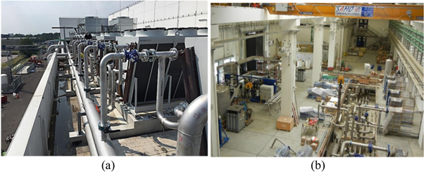
Figure 22. Cooling Plant equipment. Installation (a) on the roof, (b) inside the auxiliary hall.
Download figure:
Standard image High-resolution imageThe potential radio-activation of the coolant makes the cooling system design even more complex. Primary loops devoted to the MITICA components are the most affected by the possible presence of activated corrosion products in the water. Therefore, specific filtering sections, the coolant containment, and clearance procedures have been developed and will be implemented to guarantee the safety of workers and population.
4.3. Vacuum and gas injection system
The Vacuum and Gas Injection System (GVS) includes a common segment of the gas storage and distribution system (GSD-Shared Plant Unit) and two independent vacuum and gas injection systems dedicated to the SPIDER and MITICA experiments respectively [86]. Both the installation of the GSD-Shared Plant Unit and of the SPIDER Plant Unit, which includes the vacuum system, the gas injection system and their control system are completed and commissioning is presently in progress. The findings from the installation of the SPIDER Plant Unit have given inputs for the revision of the design and interfaces with other plants of the MITICA GVS Plant Unit, whose installation is planned in 2017. Figure 23 gives a view of turbomolecular and cryogenic pumps installed around the SPIDER Vacuum Vessel.

Figure 23. View of turbomolecular and cryogenic pumps installed around the SPIDER Vacuum Vessel.
Download figure:
Standard image High-resolution image4.4. High voltage padova test facility
The High Voltage Padova Test Facility (HVPTF) [87] is the ancillary laboratory of the NBTF, aimed to give support to the design of components subjected to high DC voltage in vacuum, to test different techniques of voltage conditioning, and to give experimental validation to voltage breakdown models.
The facility presently has a bipolar structure, consisting of two power supplies with opposite polarity, each one rated for 400 kV DC/1 mA, that feed two electrodes via two alumina feedthroughs. The electrodes are inside a 2 m3 vacuum chamber, horizontal axis, with a vacuum level around 10−5 Pa. So, the highest achievable inter-electrode voltage is 800 kV. The highest voltage reached so far is 550 kV, taking advantage of the so-called pressure effect. It has also the possibility to operate with a smaller, bipolar setup, with a 0.5 m3 vacuum chamber, two power supplies each rated for 150 kV/8 mA, two alumina feedthroughs, which allow changes to the gap length without breaking the vacuum. A picture of the facility is shown in figure 24.

Figure 24. View of the HVPTF 800 kV setup. The tank with the lead screening on the top and the two ±400 kV/1 mA power supplies are shown. Connection to the electrodes is made via coaxial XLPE cables.
Download figure:
Standard image High-resolution imageThe facility has a very high degree of immunity to EMI, to allow safe operation under very frequent voltage breakdown events. This feature has been obtained with a substantial coaxial structure and extensive use of fiber optics or insulated power supplies for measurements and control. The control and measurement system is based on Labview. Data storage and visualization are based on the MDSplus environment, which allows a great amount of data, deriving from long-lasting voltage application experiments, to be handled easily.
Recently, the HVPTF has been equipped with an x-ray energy spectrum analyzer, which should help in determining the role of x radiation in the process. Figure 25 shows a graph indicating the correlation between current, energy and intensity of the x-rays emitted by the interaction between accelerated electrons and anode.

Figure 25. Time evolution of current from the two 400 kV power supplies (top) and voltage applied by the two power supply (bottom). Time evolution of the emitted x-ray energy spectrum (centre); the colour corresponds to the fluence: the warmer the colour, the higher the fluence.
Download figure:
Standard image High-resolution imageThe main scientific result obtained from the experimental campaign in the HVPTF was the identification of the changes in the Paschen curves under the application of magnetic field [59]. This research allowed identification of the strategy to perform voltage conditioning in the presence of a magnetic field. Other achievements regard the validation of the Voltage Holding Predictive Model (VHPM), which allows the prediction of the voltage breakdown probability curve for any multivoltage-multielectrode configuration [96, 97]. The VHPM has been applied in the design of the MITICA accelerator [58].
4.5. Radio frequency test facility
The R&D activity aims to investigate issues related to the design and operation of RF drivers for NB negative ion sources. The task presently in progress is the characterization of the dielectric strength of low pressure gases when subjected to an RF electric field, with the final aim of verifying the electrical insulation design of the RF coils of the drivers of SPIDER and MITICA drivers. The operating conditions of the ion source coils are reproduced in terms of voltage (magnitude and frequency), gas species, pressure and materials, in a dedicated test facility called High Voltage Radio Frequency Test Facility (HVRFTF).
The setup of the HVRFTF (see figure 26) and the characterization of the RF circuit have been completed in 2016. The integrated commissioning has been successfully performed with the contemporary operation of the vacuum systems (pumping and gas injection) and the RF circuit able to reach around 10 kV. First tests have been carried out with Argon from 10−5 to 10−2 mbar and first Paschen curves have been derived.

Figure 26. Final setup of the high voltage radio frequency test facility.
Download figure:
Standard image High-resolution image4.6. Caesium oven testbed
A caesium oven testbed is part of the NBTF, having the following engineering and physics goals:
- qualification and acceptance tests for SPIDER caesium ovens in support of procurement;
- caesium diagnostic commissioning: Surface Ionization Detector (SID) and Laser Absorption Spectroscopy (LAS);
- caesium oven maintenance: cleaning, refilling, commissioning;
- caesium management during SPIDER and MITICA operations;
- caesium oven calibration and characterization in parallel to SPIDER and MITICA campaigns;
- caesium oven development: testing of alternative solutions (e.g. pellets for MITICA);
- studies on caesium deposition and interaction with gas and/or plasma.
After an initial phase dedicated to supporting SPIDER caesium oven procurement, the operational phases of the testbed will consist of: oven commissioning; commissioning of SPIDER caesium oven and caesium flux characterization and finally, support to caesium campaigns for SPIDER experiment. Further oven development and studies for MITICA and HNB might be carried out afterwards. Figure 27 shows a CAD view of the caesium oven test facility.

Figure 27. CAD view of the caesium oven test facility.
Download figure:
Standard image High-resolution image
4.7. Numerical tools
As mentioned above, simulations were carried out using existing commercially available numerical codes (e.g. OPERA 3D [88]), or codes developed in the past within the ion beam community (e.g. SLACCAD [89], EAMCC [90]). Dedicated numerical models were also specifically developed or improved, verified or validated in dedicated experiments when possible). The most significant are the following:
- Bypo [91] and ACCPIC [92] simulate the beam extraction and acceleration in a 2D domain, using ray tracing/fluid approach and particle in cell technique respectively.
- NBIMAG simulates the magnetic configuration produced by a complex combination of permanent magnets and current currying conductors using an integral approach [93] and optimizes according to a user-defined objective function [94, 95].
- The Voltage Holding Predictive Model VHPM [96] estimates the breakdown voltage taking into account the effect of the electrode surface and particle trajectories with a probabilistic approach [97].
- Avocado [98] evaluates the background pressure distribution in molecular regime by an integral approach; this code has been validated experimentally [99]. Molecular dynamics simulation of low-energy neutral particle interaction with surfaces has been treated in [100].
- The ray-tracing Samantha code [101] simulates the transport and neutralization of a space-charge compensated beam, taking into account the interaction with the gas target and the generation of energetic secondary particles, to obtain the heat load onto beam line components. This code has been benchmarked against the BTR code [102]. The beam space charge compensation was simulated by several codes [103, 104], adopting the Particle in cell technique in a 2D domain.
- For long-pulse operation, the BackScat [105] code has been developed to evaluate the trajectories of the stray electrons exiting from the accelerator, including scattering probabilities, and to calculate the relevant heat fluxes on beam line components [106].
- EAMCC3d [107] is a major extension of the EAMCC code, which overcome the limitation of the periodic single-beamlet calculation domain, as necessary to evaluate the edge effects in a large multi-beamlet beam geometry.
The combined use of these codes was systematically benchmarked against the experimental results obtained in the test facilities of the collaborating laboratories of QST (formerly JAEA), Naka (Japan) [108–110], IPP, Garching (Germany) [111], NIFS, Gifu (Japan) [112, 113] and NIO1 [114, 115], which is a flexible and modular beam source dedicated to providing a model for the larger sources and a versatile test bench for numerical models and innovative techniques operating in the CNR research area, where PRIMA is also located.
5. Conclusions
This paper has given a complete overview of the ITER Neutral Beam Test Facility, called PRIMA, and its two experiments: MITICA, the full-scale prototype of the ITER HNB injector; and SPIDER, the full-size radio frequency negative-ion source.
The motivations behind the NBTF construction, the mission of the two experiments: SPIDER and MITICA, the main challenges encountered during their design and the specific R&D to verify the feasibility of key parts have been discussed. The NBTF and its projects have become a reality in just a few years, from the signature of the NBTF agreement in 2011 up to now: the building construction was started in October 2012 and completed in 2015, the SPIDER integrated commissioning phase is starting, the implementation of diagnostics and control is in progress and the operation and research plan has been outlined; the procurement of several MITICA components is well advanced.
Regarding the radiation protection regulatory framework, both SPIDER and MITICA operation require compliance with legislation, codes and standards to guarantee the safety of workers involved with the experimental activity, and of people living around the facility. At the time of writing, licence for conducting a radiation practice has been obtained for SPIDER, while the licensing process is underway for MITICA.
Based on the delivery plan of the Beam Sources, the first SPIDER experimental phase is expected to start early in 2018, and MITICA in 2021; therefore, several years of operation are available for both of them before the use of the heating HNBs in ITER, where the first plasma is scheduled in 2025 and the start of the deuterium–tritium phase, requiring the HNB injectors in operation is foreseen in 2031. The NBTF experimental phase will be devoted to exploiting the SPIDER mission to prove the possibility of achieving the ITER target requirements in an ion source of the same characteristics and size. Similar considerations also apply to MITICA, mainly devoted to optimizing the Accelerator and Beam Line Components (BLC). Both experiments should provide key indications to improve the design of various components of the ITER HNB before its technical specifications are frozen, and then to optimize their performance in terms of reliability and availability, thus contributing to significant risk mitigation for their successful operation in ITER.
Acknowledgments and Disclaimers
The work leading to this publication has been partially funded by Fusion for Energy (F4E). This publication only reflects the views of the authors, and F4E cannot be held responsible for any use which may be made of the information contained therein. The views and opinions expressed herein do not necessarily reflect those of the ITER Organization.