
Abstract
This paper overviews the combined effects of winding, cool-down, and screening current-induced stresses in REBCO coils. First, a simulation method to model the circumferential stress modification effect due to the screening-current is overviewed. The simulation includes coil winding, cooling down, and coil charge up to the operating current. Second, we will compare the numerical simulation results with the experimental results. The numerical simulations for a dry coil and an epoxy impregnated coil agree well with the experimental results. Third, the enhanced circumferential stress did not degrade the performance of a dry winding REBCO coil, but the improved increased compressive stress buckled the coil structure. Finally, it is demonstrated that epoxy impregnation has beneficial effects in reducing the stress modification effect. However, the circumferential stress is enormously enhanced at the coil ends, sometimes resulting in degradation of the coil performance.
Export citation and abstract BibTeX RIS

Original content from this work may be used under the terms of the Creative Commons Attribution 4.0 license. Any further distribution of this work must maintain attribution to the author(s) and the title of the work, journal citation and DOI.
1. Introduction
In low-temperature superconducting (LTS) magnets, premature quenches are the most challenging problem. They are usually due to conductor motion induced by the electromagnetic force for dry wound coils [1–3] and debonding between the epoxy-impregnated coil winding and the coil form [4, 5]. Simulations of the cumulative radial stress distribution in the coil due to coil winding, cool-down, and electromagnetic force suggest how one can effectively suppress these phenomena [1–3]. If a sufficiently high compressive radial stress remains at the operating current, the conductor is tightly pressed together in the radial direction, suppressing the frictional conductor motion caused by the electromagnetic force [1, 2]. Such compressive radial stress also suppresses epoxy fracture and debonding in an epoxy impregnated coil [4, 5].
The simulation of radial stress distribution has not been investigated for high-temperature superconducting (HTS) magnets, as the conductor motion caused by the electromagnetic force does not induce premature quenches in HTS magnets as the current sharing temperature is sufficiently high. On the other hand, the most challenging problem appearing for the REBa2Cu3Oy (REBCO, RE = rare earth) coil is the sudden thermal runaway below the critical current. Such a runaway is due to permanent damage caused during cooling down [6] and by the electromagnetic force [7]. Recent investigations demonstrate that the conductor damage is related to the interaction between the axial magnetic field and the screening current [7–16]. The positive current on the conductor's upper part amplifies the outward force, while the negative current on the conductor's lower part intensifies the inward force as shown in figure 1. Thus, the phenomenon modifies the circumferential stress distribution, increasing the tensile stress on the conductor's upper part and the compressive stress on the conductor's lower part. Excessive tensile stress causes microcracks or fractures, damaging the conductor. Compressive stresses induce buckling, degrading the coil performance.

Figure 1. Additional force due to screening current. (a) Transport current in REBCO tape, (b) screening current induced by a radial component of magnetic field, and (c) Lorentz force generated by an axial component of magnetic field and no-uniform current.
Download figure:
Standard image High-resolution imageIn the first studies, the modified circumferential stress was numerically simulated based on the interaction between an axial magnetic field and the screening current [8–10]; however, we recently noticed that such a simulation gave an overestimate of the circumferential stress due to the electromagnetic force. The interaction force tilts the conductor, reducing the induced screening current, resulting in a decrease in circumferential stress, i.e., it is called a discrete coupled model, while the conventional model is a discrete sequential model [11, 12]. It has been demonstrated recently that a friction force or epoxy bonding between a pancake edge and an inter-pancake insulator suppresses the conductor's tilting and conductor damage. Furthermore, demagnetization, use of multifilamentary conductors and overshooting operation reduce the stress modification [13–15].
The coil deformation due to the screening current depends on the cumulative radial stress distribution in the coil winding. Suppose that a sufficiently high compressive radial stress remains at the operating current, then conductors are tightly pressed together in the radial direction. They do not behave individually but act as a bulk, resulting in suppressing the stress modification effect. Epoxy impregnation of the magnet winding provides similar beneficial effects [16]. Thus, the stress modification effect of the screening current for the REBCO magnets depends on the radial stress distribution and coil fabrication processes, such as dry winding and epoxy impregnation.
This paper first overview the numerical simulation methods regarding the stress modification effect of the screening current. It includes coil winding, cooling down, and coil charge up to the operating current; we will use a discrete sequential model for the coil charge. We then compare the numerical simulation with the experimental results for a dry coil, a no insulation coil, and an epoxy impregnated coil. We then discuss the adequate remedy of stress modification effects due to the screening current.
2. Numerical simulation of the effect of the screening current
In the numerical structural simulation of REBCO coils, the important issues are the forces experienced in various processes and a modeling of the winding.
The following forces and stresses in REBCO coils must be considered:
- (a)the mechanical stress due to the winding tension and the bending strain during the winding process,
- (b)thermal stress during cooling down, and
- (c)electromagnetic stress, including the effect of screening current.
Bending strain dependence and uniaxial tensile strain dependence of critical current, Ic, are the important mechanical properties of REBCO tape for application to superconducting magnets, so many groups have evaluated these properties of a REBCO tape [17–21]. We must consider the bending strain and winding tension such as the thermal stress or electromagnetic force as the internal stress in order to accurately simulate mechanical behaviors of REBCO coils.
It is necessary to pay attention to the winding deformation in REBCO coils during a cooling down process because degradation of the critical current of epoxy impregnated REBCO coils has been reported [6]. Delamination between the REBCO layer and the buffer layer occur during the cool-down in a REBCO coil bonding between the winding turns, resulting in degradation of the REBCO tape performance. On the other hand, dry winding and paraffin impregnation suppress degradation, as turns are separated because of the negligible bonding strength. In this case, the separation and movement of winding turns due to the thermal contraction must be considered in the numerical simulation.
A high Lorentz force is exerted on a high-field REBCO magnet. Generally, the coil windings are subjected to circumferential tensile stress and radial compressive stress due to the electromagnetic force. Furthermore, as shown in figure 1, in a REBCO coil, the additional electromagnetic force due to the screening current is applied to REBCO coils in comparison to assuming that a uniform current flows in the tape when designing the coil. Thus, the screening current poses a severe problem related the mechanical damage and reinforcement structure of REBCO coils. The sequential model and the coupled electromagnetic-mechanical model are reported as used in the mechanical analysis considering electromagnetic forces due to screening current [11, 12, 16]. The Lorentz forces are directly extracted from the electromagnetic analysis and applied to the elastic deformation analyses in a sequential model. In a coupled model, we consider the tilting angle and strain–critical current relationship.
In a conventional mechanical simulation of coils, the coil winding is considered as an anisotropic body in radial and circumferential directions by the rule of mixture for composite materials. The numerical simulations of a REBCO coil as an anisotropy single elastic body were reported in [22]. However, in a non-impregnated NI coil, which was proposed to promise extremely enhanced thermal stability and self-protection of REBCO coils [23], the contact situation between turns changes as shown in figure 2. A force normal to the contacting surfaces acts on the adjacent two turns when they touch each other. If there is friction between the surfaces, shear forces may be created resisting the bodies' tangential motion (sliding). Thus, the screening current-induced force affects the delamination, tilting, buckling of REBCO tape and so on. Therefore, a single elastic body model does not lead to accurate numerical results. Some groups have recently reported and discussed the deformation of REBCO coils in numerical simulations, considering the contact and separation of turns [11, 12, 16]. The contact problems are generally nonlinear owing to changing boundary conditions. One numerical algorithm for a contact problem is the penalty method, however a simple algorithm using a gap element or contact element was incorporated into a finite element method in this study [16]. We considered the winding stress, thermal stress, and electromagnetic stress in the sequence. The procedure of this simulation is follows:
- (a)First, the stress distribution was calculated subject to the winding tension and the bending strain in winding process.
- (b)Next, the deformation was simulated considering the thermal strain in cooling process and the calculated stress in winding process as internal stresses.
- (c)Finally, the stress distribution was calculated subjected the electromagnetic force considering the screening current in the charging process.

Figure 2. Contact conditions. (a) Contact, (b) separation, (c) slide. Figure adapted from [16] (SUST, 2021).
Download figure:
Standard image High-resolution imageHere, the cases of 10 T class REBCO coils are introduced from [16]. This coil comprises 22 single-pancake stacked coils. Winding, cool-down and electromagnetic force screening current-induced effects are considered. Figure 3 shows the numerical results for (a) a dry winding coil wound with insulated REBCO tape and (b) epoxy impregnated coil wound with no insulated tape. They show the circumferential stress due to electromagnetic force, including screening-current effect, that is achieved for the uppermost single pancake coil; the red solid line shows the stress in the upper side, while the blue solid line is that in the lower side. In the dry winding coil seen in figure 3(a), the development of the stress separation due to the screening current is remarkable. The insulation coating REBCO tape shrinks during a cooling process. It easily deforms against the force received by the REBCO tape during an excitation process. The REBCO tapes in winding move and deform according to the nonuniform electromagnetic force distribution due to a screening current. Therefore, stress modification (i.e. separation) is significant, as seen in figure 3(a). On the contrary, in the epoxy impregnated coil, the coil winding acts as a bulk, therefore, stress modification (separation) is much reduced. Epoxy impregnation has beneficial effects in reducing stress modification and coil degradation. However, if the radial stress is enhanced after cooling down, the radial stress exceeds the acceptable transverse stress, a typically ∼10 MPa, resulting in conductor delamination [6].

Figure 3. Effect of epoxy impregnation on the stress modification due to screening current. (a) Dry winding coil wound with insulated REBCO tape, (b) epoxy impregnated coil wound with no insulated tape. Figure adapted from [16] (SUST, 2021).
Download figure:
Standard image High-resolution image3. Comparison between experimental results and numerical simulations of the stress modification and coil degradation due to the screening current
3.1. Circumferential stress modification effect due to the screening current for a small dry coil
3.1.1. Experimental results.
The experimental apparatus seen in figure 4 demonstrates the stress modification effect due to the screening current [9]. Two five-turn REBCO dry pancake coils, 79.5 mm in inner diameter, were installed inside a 5 T NbTi coil; we used a 4 mm wide SuperPower REBCO tape for both coils. Coil A is fixed in the middle of the upper half of the 5 T NbTi coil, while Coil B is at the top end of the NbTi coil. We bonded three strain gauges on the outer surface of each test coil for measuring the circumferential stress distribution along the conductor width, as seen in figure 4. The operating current for Coil A is 693 A under the external magnetic field of Bz = 4.8 T and Br = 0.4 T, while that for Coil B is 300 A under Bz = 2.8 T and Br = 1.6 T. We tested them at 4.2 K. A graph at the center of figure 5 shows the measured circumferential stress (strain) distribution vs position along the conductor width; ZRE = −2 mm is the lowest edge, while ZRE = 2 mm is the highest edge of the conductor. The left axis shows the circumferential strain, while the right axis is the corresponding stress. The circumferential stress measured by the strain gauge increases with ZRE due to the screening-current effect, as expected from the numerical simulation described in the previous section; note that each conductor separates from the other. The circumferential stress at ZRE = 1 mm for Coil A is 615 MPa, about double that for Coil B, 225 MPa, due to a higher magnetic field, Bz , and higher coil current density. Another unique feature for Coil B is that the circumferential stress at the lower part of the conductor at ZRE < −1 mm seems to be compressive. They will be compared with the numerical simulation later.
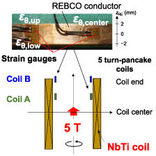
Figure 4. Experimental apparatus demonstrating the circumferential stress modification effect due to the screening current.
Download figure:
Standard image High-resolution image
Figure 5. The measured circumferential stress (strain) distribution vs position along the conductor width. The degradation only appears in Coil B, due to the buckling.
Download figure:
Standard image High-resolution imageFigure 5 also shows the coil performance at 77 K after the charging experiment. Coil A on the right does not show degradation, although the maximum circumferential stress is high. On the contrary, Coil B shows degradation. We can infer that the circumferential compressive stress results in buckling damage at the lower part of the conductor, degrading the coil performance. Figure 6 proves the buckling at the lower edge of the coil, showing cracks and delaminations on the right and critical current degradation on the left.
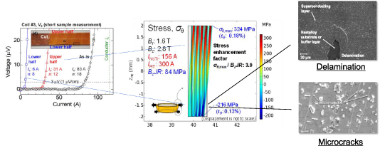
Figure 6. The deformed coil shape achieved by the numerical simulation. The conductor performance is severely degraded, and cracks and delamination appear in the lower half of the conductor. Figure modified from [9] (IEEE, 2020).
Download figure:
Standard image High-resolution imageThe screening current effect results in the circumferential stress hysteresis for Coil B, as shown in figure 7. We observed a hysteresis effect while the NbTi coil current is swept up and down without the any current flow in the test coil; the interaction between induced screening current and axial magnetic field of the NbTi coil results in a circumferential stress distribution. The hysteresis is due to the difference in induced screening current during charging and discharging the coil. The circumferential strain for ZRE = −1 mm seen by a solid green line is negative (i.e. compressive) while increasing the NbTi coil current, resulting in buckling damage of the coil. Thus, stress modification due to the screening current results in (a) excessive tensile damage at the upper edge of the conductor and (b) buckling damage at the lower edge of the conductor.

Figure 7. Hysteresis of the measured circumferential strain due to the interaction between screening current and the axial magnetic field for Coil B; the horizontal axis is the NbTi coil current. There was no transport current flow in the five-turn coil. Figure adapted from [9] (IEEE, 2020).
Download figure:
Standard image High-resolution image3.1.2. Numerical simulation results.
The numerical simulations of the stress modification effect due to the screening current for the five-turn REBCO dry pancake coils, as seen in figure 4 [9], were performed. This coil is a dry wound with polyamide-insulated REBCO tape conductor. The thickness of the insulator is 35 µm; each turn in the dry coil deforms separately and move freely. The contact between turns is modeled using gap elements. In the simulation, winding, cool-down and screening current-induced stresses are considered. The simulation circumferential strains are shown in figure 8(a). The solid green line shows the numerical simulation results for Coil A, and the solid blue line is for Coil B. The strain shown in figure 8 includes both electromagnetic and bending contribution. Turns are separated from each other, as seen in figure 8(b). Therefore, the circumferential strain distributions along the REBCO tape width, considering a screening current, is different from that for uniform current case (green and blue dashed lines). The circumferential stress is concentrated at the top of the tape while it decreases at the bottom. As seen in figure 8(a), the simulation results (solid lines) agree very well with the experimental results (triangle); the maximum tensile strain 0.6%, corresponding to ∼800 MPa at ZRE = 2 mm. In comparison, the maximum compressive strain for Coil B is −0.06%, corresponding to −100 MPa at ZRE = −2 mm. The conductor is not degraded in the former case in the experiment, as seen in figure 5. On the contrary, it is the degraded in the latter case as seen in figures 5 and 6. Thus the numerical results are in reasonable agreement with experiments.
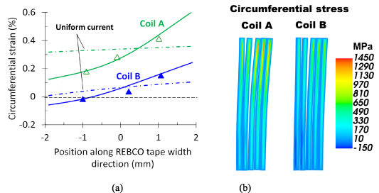
Figure 8. The numerical results on the strain and stress modification effect due to the screening current for the experimental apparatus as seen in figure 4. (a) The computed circumferential stress (strain) distribution vs position along the conductor width. The strain shown includes both electromagnetic and bending contribution. (b) The deformation and stress circumferential distributions in a cross-section of winding.
Download figure:
Standard image High-resolution imageBased on the numerical simulation, we observed the hysteresis of the circumferential strain for Coil B as seen in figures 9(a)–(c), agreeing very well with the experimental result seen in figure 7. Figure 9(d) shows the deformation and circumferential stress distributions in a cross-section of winding. Although the hysteresis of circumferential strain in figures 9(a)–(c) is very similar to the experiment, the values are different. The reason is errors in the mechanical properties of the REBCO conductors or the plastic deformation of composing materials.
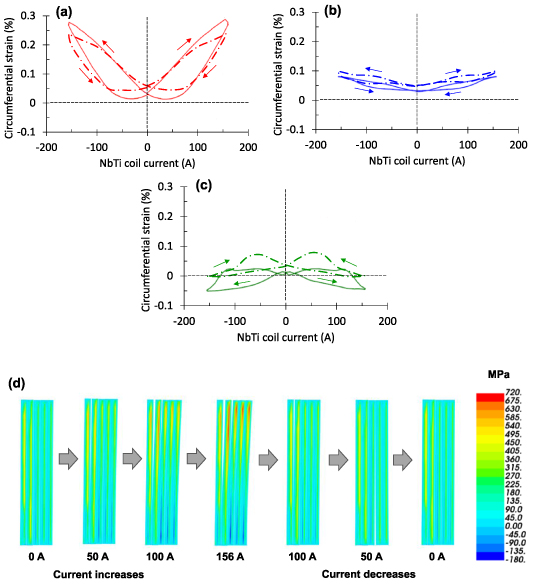
Figure 9. Numerical simulation (dashed line) on the hysteresis of the circumferential strain at (a) upper edge, (b) center and (c) lower edge vs the NbTi coil current, agreeing well with the experiment (solid line); (d) the deformation and circumferential stress distributions in a cross-section of winding.
Download figure:
Standard image High-resolution image3.2. Circumferential stress modification effect due to the screening current for an epoxy impregnated coil
3.2.1. Experimental results.
As described in the previous section, if the cumulative radial stress for a coil is not sufficiently negative, conductors are separated from each other, and therefore each conductor reacts individually to the electromagnetic force. In this case, the REBCO conductor is bent in wave pattern due to the circumferential stress distribution along the width, as the REBCO conductor's flexural rigidity is minimal. This bending sometimes results in degradation of the coil performance. On the contrary, as described in the last section, if the compressive radial stress is significant, the conductor is tightly pressed together, enhancing the flexural rigidity of the winding. Thus, we can suppress the wavy bending of the conductor, reducing the stress modification and degradation of the coil performance. Higher winding tension and thinner insulation, such as a no-insulation coil, are adequate for suppressing the coil degradation [16].
On the contrary, in the case of epoxy-impregnated coils, the coil winding acts as bulk; therefore, the flexural rigidity of the winding is significant regardless of the cumulative radial stress. Thus, we can control the stress modification effect and suppress degradation of the coil performance, as described in the previous section [16].
However, a drawback of REBCO conductors is the weakness against peeling [6, 24]. If we impregnate a REBCO coil with epoxy resin, tensile stress is created between a REBCO conductor and the epoxy resin during cool-down, resulting in peeling off a REBCO layer, thereby degrading the coil performance [6]. An electrodeposited polyimide layer spread over REBCO surface [25] decouples the REBCO-conductors from the epoxy resin, suppressing the peeling damage during cool down [6]. We will show charging test results of an epoxy impregnated REBCO coil wound with a polyimide electrodeposited REBCO conductor.
A 10 μm thick polyimide layer is electrodeposited on the REBCO conductor's surface. A four-turn solenoid, 80.0 mm in inner diameter, 81.0 mm in outer diameter, and 94.8 mm in height, was produced. A wet winding process with epoxy resin was employed as seen in figure 10, as vacuum impregnation was difficult due to the minimal space between turns and layers.

Figure 10. Pictures of the coil wet wound with epoxy resin using the polyimide-electrodeposited REBCO tape conductor. (a) Polyimide electrodeposited REBCO tape conductor. (b) Wet winding with epoxy resin. (c) Coil appearance after curing the coil.
Download figure:
Standard image High-resolution imageFigure 11(a) shows the coil voltage vs current at 4.2 K in an external magnetic field of 11 T [26]. Resistive voltage and voltage spikes do not appear below 406 A, as shown by the red open circles. However, the coil voltage suddenly jumped to 0.9 mV at 408 A with a time duration of <40 ms, as shown in figure 11(b). The coil voltage becomes constant after the voltage jump, and therefore the voltage jump is due to the sudden failure of the REBCO conductor. The 408 A value is 65% of the short sample critical current, corresponding to the circumferential tensile stress, i.e. BjR, 469 MPa; B is the axial magnetic field, j is the coil current density, and R is the coil radius. This tensile stress is not amplified by the screening current as the coil is impregnated with epoxy resin; the circumferential tensile stress is insufficient for conductor failure. While discharging the REBCO coil, the resistive voltage remains in the range from 410 A to 250 A. The irreversible behavior results from conductor failure by the electromagnetic force; the coil critical current decreases from 621 A to 250 A, 40% of the initial value.

Figure 11. (a) The coil voltage vs REBCO coil current. (b) Transient voltage signal at the voltage jump. Figure adapted from [26] (Elsevier, 2018).
Download figure:
Standard image High-resolution imageAfter the coil charge test, we found a conductor fracture at a top turn of the 2nd layer, as seen in figure 12 [26]. Epoxy did not satisfactorily penetrate cavities at both ends of the solenoid coil. Therefore, the top turn of the second layer was not adequately supported by adjacent layers. Thus, it behaves like a self-supported single turn; the stress enhancement due to screening current becomes remarkable, resulting in conductor fracture.
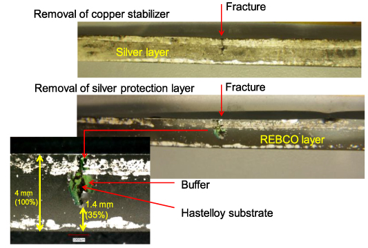
Figure 12. An optical micrograph of the REBCO conductor fracture. The fracture length is 65% of the conductor width. Figure adapted from [26] (Elsevier, 2018).
Download figure:
Standard image High-resolution image3.2.2. Numerical simulation.
Figure 13 shows the numerical results for layer wound epoxy-impregnated coil as shown in figure 10. In epoxy impregnated coil, the coil winding acts as a bulk; therefore, stress modification is much reduced as seen in figure 3; i.e. epoxy impregnation has beneficial effects in reducing stress modification and coil degradation [16]. However, as seen in figure 13, the stress enhancement due to screening current becomes remarkable at both ends of the layer-winding coil, as they are not supported by the adjacent layer's tape conductor. Based on the numerical simulation, the enhanced tensile stress at the conductor's top edge becomes as high as 1.3 GPa, sufficient for conductor fracture., Thus, a conductor fractures at a top turn of the 2nd layer as shown in figure 12. The simulation result is reasonable for experiment. The top turns of layer winding were isolated from adjacent layers and are not adequately supported by adjacent layers, even if the coil is impregnated with epoxy resin. As seen in figure 13(b), the tensile stress dramatically decreases if we fill the space at both ends of the coil winding with stainless steel tape.
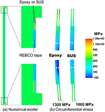
Figure 13. The numerical results on the stress distributions for the experimental apparatus as seen in figure 10 [26]. (a) 2D numerical structure model for a cross-section of layer winding and (b) circumferential stress for the layer-winding coil; both ends are filled with epoxy and stainless steel.
Download figure:
Standard image High-resolution image3.3. Hoop stress modification due to the screening current obtained for a 30 T class LTS/Bi-2223/REBCO magnet
3.3.1. Experimental results.
As a step towards developing a 1.3 GHz NMR magnet (30.55 T) [27], we developed a 30 T class ultra-high field (UHF) magnet comprising a REBCO inner coil, a Bi2Sr2Ca2Cu3Ox (Bi-2223) middle coil, and an LTS outer coil [28]; at the operating field of 30.5 T, the REBCO coil generates 9.3 T, the Bi-2223 coil is 4.0 T, and the LTS outer coil is 17.2 T. The stress modification effect for the 30 T class UHF LTS/Bi-2223/REBCO magnet is described here.
The REBCO conductor used for the REBCO inner coil is 4.03 mm in width and 0.097 mm in thickness. It is 17.6 mm in inner diameter, 67 mm in outer diameter, 40.1 mm in length; the number of turns is 9 (turns) × 180 (layers). A coil was wound with a winding tension of 4.9 N (12.5 MPa). We inserted an interlayer laminate sheet between each winding layer; the sheet comprises an 8 μm thick copper and 18 μm thick polyethylene terephthalate layer. A copper sheet vertically shorts the turns, and therefore this coil is a kind of no-insulation coil; we call this coil an intra-layer no-insulation (LNI) coil [29]. A 25 μm thick nickel alloy sheet overbanded the REBCO coil with a winding tension of 5 N (50 MPa); the over banding thickness is 2.1 mm. While charging the magnet, we measured a circumferential strain of the outer surface at the top of the over-banding.
After charging the outer LTS coil to 17.2 T, the current of the series-connected REBCO and Bi-2223 coil was gradually increased. In the first test, the magnet was charged to 30 T without quenches and discharged. The second test reached 31.4 T and was quenched. After the coil quench, we tested the magnet in liquid nitrogen, and it was confirmed that the quench did not damage the magnet.
Figure 14 shows the binder's hoop strain vs HTS coil current measured in the first test (figure 14(a)) and the second test (figure 14(b)). The strain shows a hysteresis, which demonstrates that the strain is due to the screening current.

Figure 14. (a) Circumferential strain vs coil current for the first test; hysteresis of the circumferential strain vs coil current appears for the first run (30 T). (b) The circumferential strain vs HTS coil current for the second run. The coil was quenched at 31.4 T, although the coil was not damaged.
Download figure:
Standard image High-resolution image3.3.2. Numerical simulation result.
The numerical simulations of the stress for the 30 T LNI coil were performed. The 2D numerical structure model for a cross-section of layer winding is adopted, as shown in figure 15. We considered the detailed structure, such as the inserted interlayer laminate sheet and over-banding. Figure 16 shows the numerical results of the circumferential stress and strain distributions in cross-section at 30 T, increasing at the top and bottom of the coil because of the screening current. The numerical circumferential strain at the top of the over-banding is ∼0.25%, as seen in figure 16(b), 25% larger than the experimental result, ∼0.2%, seen in figure 14(b) Then the REBCO winding experiences the maximum circumferential strain of ∼0.7%, corresponding to the stress of ∼1.0 GPa. Figure 17 shows the numerical results of circumferential and radial stresses vs radius at REBCO layer in the uppermost turns; the red solid line shows the stress in the upper side, while the blue solid line is that in the lower side. As seen in figure 17(a), the circumferential stress at upper side is higher than that of lower side, as they are not sufficiently supported by the adjacent layer's polyimide sheet. Furthermore, the circumferential stress decreases in the outer turns by the effect of over-binding, as seen in figure 17(b).

Figure 15. 2D numerical structure model for a cross-section of 30 T LNI coil.
Download figure:
Standard image High-resolution image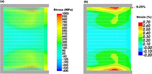
Figure 16. Numerical results of the circumferential (a) stress and (b) strain distributions in cross-section at 30 T.
Download figure:
Standard image High-resolution image
Figure 17. Numerical results of (a) circumferential stress and (b) radial stress at the uppermost turns; the red solid line shows the stress in the upper side, while the blue solid line is that in the lower side.
Download figure:
Standard image High-resolution image
The conductor damage was not observed in the experiment. Therefore, the simulation gives an overestimate of the circumferential stress and strain compared with the experiment. We can assume that the electromagnetic force tilts the conductor, and the induced screening current reduces, resulting in a decrease in circumferential stress. The friction between tapes can be dealt as parameter for matching between experimental and numerical result. In particular, it is possible that the friction effect shows a significant impact in high field layer-wound magnet because of large electromagnetic force. The mechanisms of sliding motion and its effects at 4.2 K were studied in detail for several metal/insulator pairs in superconducting magnet windings models [30]. It reported that the friction coefficient was 0.2–0.3. However, we have not verified the friction effect in REBCO winding coil yet. The friction between tapes will be an issue to be addressed in the future.
4. Summary
This paper focuses on the combined effect of winding, cool-down, and screening current-induced stresses in a REBCO magnet. They are summarized as follows:
- (a)The numerical simulation methods on the high field magnets' circumferential stress modification due to the screening current are overviewed. The simulation includes coil winding, cooling down, and coil charge up to the operating current; a discrete sequential model was used for the coil charge.
- (b)The numerical simulation results agree very well with the experimental results achieved for a dry coil and an epoxy impregnated coil. In this numerical simulation, we did not consider that the interaction force tilts the conductor, reducing the induced screening current. Therefore, the simulation of large deformation in high-field magnets gives an overestimate of the circumferential stress and strain.
- (c)The enhanced tensile stress did not degrade the performance of a dry winding REBCO coil. Still, the improved compressive stress buckled the coil structure. We must take care to remove such compressive stress parts from the coil winding.
- (d)Epoxy impregnation has beneficial effects in reducing stress modification due to the screening current and coil degradation in pancake-winding coils and in layer-winding coils supported by the adjacent layer's tape conductor and its winding tension. However, the circumferential stress is enormously enhanced at layer-winding coils end turn resulting in conductor damage, as the turn is isolated from adjacent layers. The top turns of layer winding are isolated from adjacent layers and are not adequately supported by adjacent layers, even if the coil is impregnated with epoxy resin.
Acknowledgment
The part of this work was supported by JST-Mirai Program Grant No. JPMJMI17A2, Japan.
Data availability statement
All data that support the findings of this study are included within the article (and any supplementary files).