

Abstract
We are reporting on the conversion of gas/air flow energy in pipes to electrical signals using the triboelectric effect. A flapping triboelectric generator design with all freestanding flexible films is introduced in this regard. The generator can be integrated within a regular pipe infrastructure, as it is independent of the pipe material, for implementing the triboelectric effect. All flexible materials are used to develop the triboelectric generator, utilizing a simple fabrication process that is easily scalable. The performance of the triboelectric device was influenced by several physical parameters, as well as by the gas flow speed, which has been optimized here for a pipe diameter of 5 cm. The triboelectric generator implementing a flexible silver material in combination with polytetrafluoroethylene (PTFE) exhibits 100% higher optimum average power output compared to a generator made of PTFE and polyurethane. A harvester unit with two pairs of triboelectric films with an active film area of 5 × 3.3 cm2 with 6 mm gaps was demonstrated. The device produced total average power of 1.64 mW across an optimum load resistance of 16.7 MΩ under the air flow speed of 9.8 ± 0.2 m s−1.
Export citation and abstract BibTeX RIS
1. Introduction
The rise of new digital industrial technology, industry 4.0, has enabled companies to transform their value chains into more flexible, faster, and efficient processes for high-quality goods production at a lower cost. A greater number of sensors and communication modules are being integrated into industrial machines for automation. In addition, with the adoption of the Internet of Things more and more sensors have been incorporated into home appliances, vehicles, physical devices, and even infrastructures at remote geographical locations for real-time monitoring and security. Due to miniaturization and advanced manufacturing processes, nowadays, electronics exhibit lower power consumption. Unfortunately, conventional power supplies lack portability and batteries have limited lifespans that make it difficult to maintain these sensors. Therefore, the current trend is focused toward developing self-powered sensors and/or harvesting energy from the ambient environment as renewable and sustainable energy sources. Among different green energies sources, mechanical/kinetic energies are abundant in nature and can be harnessed to power electronics [1, 2].
Mechanical energies can be transformed to an electric signal applying several conversion principles, namely, electromagnetic [2, 3] and piezoelectric [4, 5]. The main drawbacks of these mechanisms are complex architectures, complicated manufacturing processes and high cost. Since its first discovery in 2012 [6], the triboelectric nanogenerator (TENG) has gained increased attention for use as a mechanical/vibration energy converter due to its simple design, fabrication process, and high efficiency [7]. The TENG implies contact electrification and electrostatic induction mechanisms [8]. Compared to other mechanisms, a wide range of materials can be used to develop a TENG [9], with the only constraint being implementing material pairs with opposite charge affinities to facilitate contact electrification during friction. TENGs can be used for mechanical/kinetic energy scavenging [10–14], as well as self-powered sensors [15–20].
Among the different forms of mechanical energies, wind energy is unlimited, environmentally friendly, and readily available in nature, but is unfortunately underutilized. In recent years, several TENGs have been developed in a variety of shapes and designs for energy harnessing from mechanical energies [8, 10, 21–24], including wind flow energy scavenging [25–30]. Rotational motion conversion using a TENG wind energy harvester has been reported [31]. The maximum power of 6.5 μW across 1 MΩ after 400 s was obtained for the single electrode mode design with aluminum (Al) and fluorinated ethylene propylene (FEP) layers. Perez et al [32] presented a single electrode mode TENG with copper (Cu) and FEP as triboelectric layers that produced peak power of 550 μW for a wind velocity of 20 m s−1 to convert the rotation motion of a turbine with diameter of 4 cm. The single electrode mode flapping film design was developed by Yang et al [33] that generates peak power of 160 μW for a resistance of 10 MΩ and wind speed of 10 m s−1, where an FEP layer was used as freestanding film and an Al layer was fixed on the walls. Similarly, Wu et al [34] prepared a double electrode mode flapping designed TENG with an Al layer as a freestanding flag and corona-charged electric layer fixed on a wall as triboelectric layers to charge a 470 μF capacitor in 5 s under a wind speed of 18 m s−1. The stacked layer design of TENG was composed of two electrodes and a micro-pyramid patterned polydimethylsiloxane (PDMS) layer and Al as active layers that showed capability of producing a maximum power output of 0.903 μW for the resistance of 10 MΩ and a wind speed of 3 m s−1 was reported by Seol et al [27]. A TENG with PDMS and polyethylene terephthalate (PET) layers with electrodes was reported to generate average power of 0.42 μW across 10 MΩ for a wind speed of 5.8 m s−1 [35]. In this case, the flapping design was created by deforming PET layers by applying heat to make an arc shape and joining one end directly to the polytetrafluoroethylene (PTFE) surface. The wind-rolling TENG design to harness wind energy due to ration of a lightweight dielectric sphere along the vortex whistle substrate patterned with multiple silver electrodes was also reported [26]. Bian et al [36] introduced a bionic TENG composed of supercells with a leaf and stem structure made of Al and PTFE that produced peak power of 3.6 mW for the optimum resistance of 60 MΩ at a wind speed of 11 m s−1. In addition, Zhao et al [37] reported a double electrode mode freestanding flag-type TENG by weaving polyimide (PI) and nickel (Ni) belts as functional layers for high-altitude wind energy harnessing.
In recent years, TENG-based wind energy harvesting has shown some progress. However, there are very few studies performed on energy harvesting using the triboelectric effect from the gas/air flow inlet, outlet, and ventilation, such as flow through regular infrastructure pipes/tubes frameworks. Almost all vehicles/transports, industrial machinery, infrastructures (e.g., industrial, laboratory, and home buildings) have gas exhaust mechanisms and ventilation systems. The gas/air flow energy through those structures, that is generally overlooked and wasted in daily life, could be a valuable source for small-scale energy harvesting to power sensing systems embedded inside or mounted on these structures. In this work, we present a self-operating triboelectric generator made of flapping triboelectric films for energy harvesting from gas flow in pipes. The proposed design can easily be integrated with the existing pipes in an infrastructure since it does not require any adaptation of the pipe materials to apply the triboelectric principle. The triboelectric generator is composed of freestanding active films demanding simple preparation and assembly. Among the different materials investigated, the pair made of flexible PTFE and silver (Ag) films provided the highest output power. For an optimized area of 3.3 × 5 cm2 and a gap of 6 mm, an average of 766 μW was harvested at an air flow speed of 9.8 ± 0.2 m s−1 in a pipe with a diameter of 5 cm. A multi-pair design is introduced to boost the output using optimized geometrical parameters.
2. Materials and methods
2.1. Design and materials
This work introduces a standalone triboelectric generator with a freestanding flapping film design for energy harvesting from gas flow in pipes for air flow speeds up to 20 m s−1. Figures 1(a) and (b) illustrate a schematic diagram of the cross-section and three-dimensional (3D) view of the freestanding triboelectric design. The design consists of two triboelectric layers with different charge affinities assembled facing one another using plastic holder rim and finally mounted on a pipe. Their corresponding electrodes acted as charge collectors. The PTFE was selected as a negative triboelectric layer due to its strong negative charge affinity. A conductive XYZ-axis double-sided adhesive tape layer with 3D networks of electrically conductive fibers was used as the electrode for the PTFE layer. The XYZ-tape has a very strong adhesion with the PTFE surface that can withstand high frequency vibration without delamination. Since the XYZ-tape is ultra-soft and highly flexible, it does not stiffen the PTFE foil structure after integration. As a positive triboelectric layer, two flexible materials were considered, namely, polyurethane (PU) due to its high positive charge affinity, and a new conductive and flexible casted Ag film. In these cases, PI foil was implemented as a support film to prepare the PI:Ag:PU and PI:Ag layers. Since the casted Ag and PU layers were thin, soft, and flexible, the mechanical strength of the silver and PU films originated mainly from the mechanical properties of the PI substrate. For the PI:Ag:PU structure, Ag was implemented as the current collector, whereas for the PI:Ag layer, Ag performed both as an active triboelectric layer and a current collector.

Figure 1. Schematic of (a) cross-section view and (b) 3D view of freestanding triboelectric design of the gas flow energy harvester with PTFE and PU as functional layers.
Download figure:
Standard image High-resolution imageThe geometric parameters of the device are listed in table 1. Experiments were conducted for a fixed pipe diameter of 5 cm, as recommended by our industrial partner. A fixed and maximum width of 3.3 cm for the triboelectric films was maintained to avoid obstruction of their vibration from the wall of the pipe. The spacing between the active layers from 2−6 mm were investigated since larger spacing led to more obstruction from the wall of the pipe and less vibration. Similarly, the lengths of the functional films were varied from 3−5 cm. Longer films resulted in reduced motion of the films within the confined space because of higher obstruction by the pipe wall, and the harder impact on the wall accelerated their deterioration. On the contrary, a smaller film length raised the structural rigidity and significantly reduced the active contact area of the layer during vibration.
Table 1. Physical parameters of the triboelectric gas flow energy generator.
| Physical parameters | ||
|---|---|---|
| Width of the film [cm] | : | 3.3 |
| Length of the film [cm] | : | 3, 4, 5 |
| Spacing between layers [mm] | : | 2, 4, 6 |
| Thickness of PTFE layer [μm] | : | 30 |
| Thickness of XYZ-tape [μm] | : | 100 |
| Thickness of Ag layer [μm] | : | 30 |
| Thickness of PU layer [μm] | : | 60 |
The commercial PTFE foil was purchased from Angst + Pfiste. The XYZ-axis conductive Scotch tape (9719, 3M), a silicone-based electrically conductive double-sided tape, was acquired from Digi-Key. The casted silver layer was prepared using commercial Ag 520EI conductive paste from Chimet (Italy), a elastic formable conductor with high silver loading providing a high-quality conductive network under deformation. The material is screen printable, provides high adhesion between layers with minimum voids, and contains no materials that can migrate, which means reliability under mechanical stress.. The PU (MM4520) was supplied by SMP Technology Inc. The polyimide (PI) foil, which was used as substrate, with a thickness of 75 μm, was provided by Sichuan Coxin Insulating Material Co., Ltd, Deyang City, Sichuan, China).
2.2. Experimental process
The triboelectric generator was prepared by combining PTFE as one of the active triboelectric layers paired with PU or Ag as the other. Figure 2 presents schematics of the prepared triboelectric films. The PTFE functional film was prepared using thin PTFE foil and the XYZ-axis conductive tape (XYZ-tape) was implemented as electrodes. Initially, the XYZ-tape was patterned, laminated on one surface of PTFE layer, and wired. Thereafter, the PTFE:XYZ-tape:PTFE sandwich structure was made by laminating another PTFE foil. In addition, two separate structures, namely, PI:Ag and PI:Ag:PU, were prepared as the second active layer. A film casting technique was implemented to deposit the electrically conductive Ag layer on the PI substrate to prepare the PI:Ag film, while the PI:Ag:PU structure was obtained by film casting a PU layer on a Ag electrode. Prior to the casting process, oxygen plasma treatment was conducted to enhance the adhesion between layers. The microstructure and the roughness of the surface of layers were studied using an optical digital microscope (HIROX model: KH-8700) and an optical profiling system (WYKO NT1100 from Veeco) for the scanning area of 0.93 × 1.24 mm2. The four-point probes technique was utilized to examine the electrical conductivity of the electrodes. Finally, a triboelectric generator was assembled by placing PTFE as one of the triboelectric layers paired with PU or only Ag layers as the second functional layer facing one another using a specially designed holder rim made of poly(methyl methacrylate) (PMMA). The holder rim had an identical internal diameter as the pipe diameter to promote smooth gas flow path through the joint section. 3D printed parts were then used to mount the holder rim along with the assembled triboelectric generator films in a tube/pipe with a diameter of 5 cm. Figures 3(a) and (b) show a photograph of the freestanding gas flow energy harvester unit with a single pair of triboelectric films.
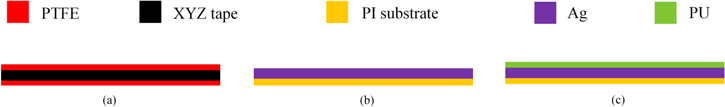
Figure 2. Schematics of prepared triboelectric layers: (a) PTFT:XYZ-tape:PTFE layer, (b) PI:Ag layer, and (c) PI:Ag:PU layer.
Download figure:
Standard image High-resolution image
Figure 3. Photograph of the freestanding triboelectric generator: (a) front view and (b) side view.
Download figure:
Standard image High-resolution imageFigure 4 presents an image of the experimental setup that was used to scavenge energy for air flow inside the pipe system. The setup mainly consists of an air blower (QF2611 4500kV brushless motor with a 64 mm 5 blade turbine, QX-motor) with a controller to produce gas flow, a sensor (Wind Sensor Rev. P, Modern Device, USA) to measure flow speed, and a holder to mount the triboelectric generator on a pipe with diameter of 5 cm. The triboelectric films were installed vertically inside the tube with respect to the ground to defy the gravitational effect while vibrating, 35 cm apart from the air blower. The flow sensor was mounted in between the air blower and harvester, 7 cm in front of the generator. The tests were performed for controlled experimental conditions, such as gaps between the films, lengths of the films, and a speed range for the gas flow below 20 m s−1 inside the tube. An oscilloscope was used to record voltage responses over varying load resistances (RL), and the corresponding output current and power values were calculated. Finally, the root-mean square (rms) values of voltage and current, and the average value of the output power was calculated over the measurement time duration of 10 s. In this work, the open-circuit voltage (VOC) and short-circuits current (ISC) were measured across the load resistances of 10 GΩ and 1 kΩ, respectively.
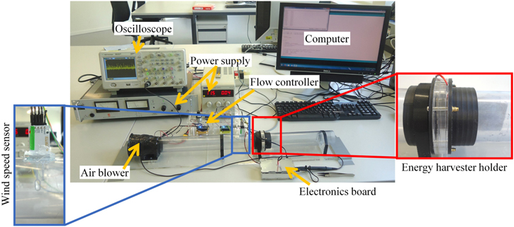
Figure 4. Photograph of the experimental setup for gas flow energy harvesting within the tube structure.
Download figure:
Standard image High-resolution image3. Results and discussion
Figure 5 shows the microstructures of the XYZ-tape and casted Ag layer. The Ag layer exhibited a rms surface roughness (Rq) of 1.7 ± 0.2 μm. The electrical conductivity of the XYZ-tape was (2.9 ± 0.4) × 102 S. The Ag layer, with a thickness of 30.0 ± 3.2 μm, demonstrated a sheet resistance of 24.0 ± 3.6 mΩ/square that is equivalent to the conductivity of (1.4 ± 0.2) × 106 S.
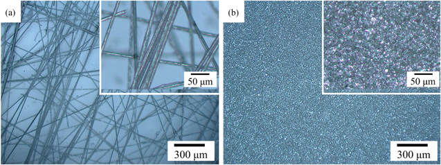
Figure 5. Optical microscopy image of (a) the XYZ-axis conductive tape and (b) casted Ag layer.
Download figure:
Standard image High-resolution imageThe fabricated devices were examined for triboelectric responses inside the developed gas tunnel under different operational conditions. Above a given flow speed, the vibration was enough to bring the triboelectric layers in contact with each other and that triggers charges transfer between functional layers due to contract electrification. Thereafter, the contact and separation between active layers causes a change of potential drops between the layers and drives electron flow between their corresponding electrodes. Initially, the PTFE and PU layers couple exhibiting the largest gap between their charge affinities were investigated. The optimum set of physical parameters of the generator was identified with respect to the pipe used with a diameter of 5 cm. Figure 6 presents triboelectric responses of the gas flow energy harvester with different geometric parameters with all the results tabulated in table 2.
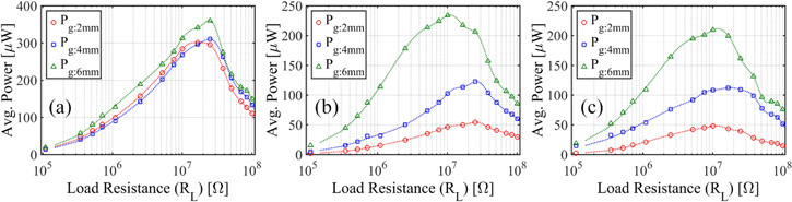
Figure 6. Average power output with respect to load resistances (RL) of triboelectric generator for fixed film width of 3.3 cm, (a) for a film length of 5 cm at an air flow speed of 10.2 ± 0.2 m s−1, (b) for a film length of 4 cm at 12.6 ± 0.3 m s−1, and (c) for a film length of 3 cm under 20.9 ± 0.5 m s−1 air flow.
Download figure:
Standard image High-resolution imageTable 2. Summary of the responses of the triboelectric film-based harvester with PTFE and PU as active layers under gas flow through the pipe.
| Triboelectric film length | Spacing | Air flow speed | Optimum load resistance | rms voltage | rms current | Avg. power |
|---|---|---|---|---|---|---|
| [cm] | [mm] | [m s−1] | [MΩ] | [V] | [μA] | [μW] |
| 5 | 2 | 10.2 ± 0.2 | 16.7 | 71.0 | 4.2 | 301.1 |
| 4 | 10.2 ± 0.2 | 25.1 | 88.3 | 3.5 | 310.5 | |
| 6 | 10.2 ± 0.2 | 25.1 | 95.0 | 3.8 | 360.0 | |
| 4 | 2 | 12.6 ± 0.3 | 25.1 | 36.9 | 1.5 | 54.4 |
| 4 | 12.6 ± 0.3 | 25.1 | 55.5 | 2.2 | 122.7 | |
| 6 | 12.6 ± 0.3 | 10.1 | 48.6 | 4.8 | 233.7 | |
| 3 | 2 | 20.9 ± 0.5 | 10.1 | 22.0 | 2.2 | 48.0 |
| 4 | 20.9 ± 0.5 | 16.7 | 43.3 | 2.6 | 112.1 | |
| 6 | 20.9 ± 0.5 | 10.1 | 46.0 | 4.6 | 209.5 |
Reduction of triboelectric films length resulted in the requirement of a higher gas flow speed to trigger the flapping motion. For a length of 5 cm, a minimum flow speed of ∼6 m s−1 was needed to trigger vibration, whereas for the lengths of 4 and 3 cm the minimum required flow speed was ∼12 and ∼20 m s−1, respectively. Moreover, the films length effects the maximum achievable wind flow speed in the currently used experimental setup. The maximum flow speed experienced a saturation at ∼15 m s−1 for the length of 5 cm, which gradually increased with the reduction of the length to reach ∼21 m s−1 for 3 cm. The effects of varying length and spacing between films on the responses of the generators were examined under the flow speeds of 10.2 ± 0.2, 12.6 ± 0.3, and 20.9 ± 0.5 m s−1, respectively, for the film lengths of 5, 4, and 3 cm.
As the result suggests, for the fixed film width and spacing between active layers, the films length of 5 cm produced the best performance. The reduction of the length of the films from 5−3 cm reduced the average power outputs from 301.1 μW to 48.0 μW for the constant films spacing of 2 mm, although the latter was exposed to an ∼2 times higher wind flow speed. Longer film lengths not only promoted vibrational motion at a lower flow speed, but also contributed to raising the active contact area of the functional layers while flapping, in which higher power values arise. Furthermore, responses of the triboelectric generator increased with the increasing spacing/gap between the functional layers for all lengths of films evaluated (figure 6). Higher spacing between films might permit progressive vibrational space and provide a higher contact-separation gap that drives comparatively more charges between the corresponding electrodes, resulting in slightly higher output responses.
Accordingly, for the triboelectric generator made of PTFE and PU active layers under the air flow speed of 10.2 ± 0.2 m s−1, the leading performance was obtained for the films with a length of 5 cm, a width of 3.3 cm, and spacing of 6 mm. This device configuration provides an rms value of the open-circuit voltage (VOC) of 1933.3 V, an rms value of the short-circuit current (ISC) of 13.6 μA, and an optimum average output power of 360.0 μW across the optimum RL of 25.1 MΩ, as presented in figure 7. The optimal geometrical parameters of a length of 5 cm, width of 3.3 cm, and spacing of 6 mm were therefore adopted for the triboelectric generator made of PTFE and Ag functional layers.
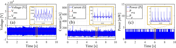
Figure 7. Responses of the triboelectric generator (with an area of 5 × 3.3 cm2 and a gap of 6 mm between them) for air flow at 10.2 ± 0.2 m s−1, (a) open-circuit voltage, (b) short-circuit current, and (c) power output across load resistance of 25.1 MΩ.
Download figure:
Standard image High-resolution imagePairing PTFE with Ag as the functional triboelectric layer resulted in ∼100% increase of the generated average output power in comparison to the couple PTFE-PU. For the air flow at 9.8 ± 0.2 m s−1 and across an optimum load resistance (RL) of 25.1 MΩ, the generator implementing the Ag layer delivered a rms voltage, a rms current, and a corresponding optimum average power output of 138.7 V, 5.5 μA, and 766.6 μW, respectively (figure 8). Although, Ag has a slightly lower positive charge affinity than PU, being electrically conductive, the Ag layer contains far more loosely bound electrons to donate to the PTFE layer during contact electrification. The higher contact electrification leads to higher potential changes between layers while contact-separation motion and thus to enhances output power.
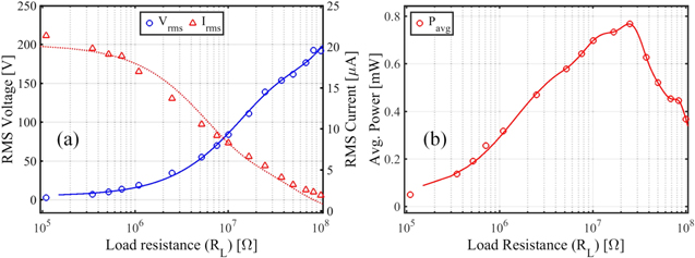
Figure 8. Responses of a generator with PTFE and Ag as active layers (with lengths of 5 cm each with spacing of 6 mm) across load resistances (RL) for gas flow at 9.8 ± 0.2 m s−1, (a) rms voltage and current responses, and (b) average power output.
Download figure:
Standard image High-resolution imageThis triboelectric harvester configuration was finally tested to study the influence of the gas flow speed on its outputs. For constant load resistances, the average power output of the generator increases with the increasing air flow speed (figure 9(a)). The operation range of the triboelectric generator made of PTFE and Ag layers with the optimum set of physical dimensions lies between ∼8 m s−1 and ∼15 m s−1. The generator produced an average power output, across the load resistance of 16.7 MΩ, of 24.3 ± 1.4 μW under the air flow speed of 5.8 ± 0.1 m s−1, which increases by 55 times to 1.3 ± 0.1 mW for the flow speed of 14.8 ± 0.3 m s−1. Figure 9(b) presents its voltage responses for different flow speeds. As observed, for the fixed load resistance, the elevated flow speeds resulted in the triboelectric films vibrating at higher frequencies, which were clearly distinguishable from the output voltage signals. In addition, the greater flow speed leads to much higher voltage amplitudes of the output responses due to the higher flapping force. The rms voltage output over the resistance of 16.7 MΩ was 20.1 ± 0.6 V at 5.8 ± 0.1 m s−1, which increases gradually for the flow speed of 10.1 ± 0.2 and 14.8 ± 0.3 m s−1 to 89.8 ± 0.5 V and 150.0 ± 2.7 V, respectively.
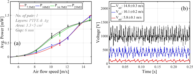
Figure 9. Responses of a generator with PTFE and Ag as active layers with lengths of 5 cm each with spacing of 6 mm, (a) average power output (P) with respect to gas flow speed, and (b) output voltage across the resistance of 16.7 MΩ for the air flow speed (Vair) of 5.8 ± 0.1, 10.1 ± 0.2, and 14.8 ± 0.3 m s−1.
Download figure:
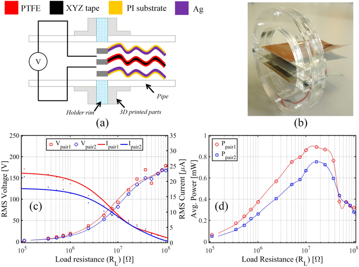
Standard image High-resolution imageTo maximize the output power generation, finally, multiple pairs of triboelectric generators can be combined in the same holder. In this regard, keeping the same predefined optimal dimensions (length: 5 cm, width, 3.3 cm, spacing: 6 cm), one PTFE:Ag:PTFE and two PI:Ag films were assembled to prepare a harvester unit with two pairs of triboelectric layers, as shown in figures 10(a) and (b). The responses of the harvester unit with two triboelectric generators are illustrated in figures 10(c) and (d). For the air flow at 9.8 ± 0.2 m s−1 across the optimum load resistance (RL) of the 16.7 MΩ, pair one generated an rms voltage and current of 121.9 V and 7.3 μA, which corresponds to the optimum average power output of 890.6 μW. Similarly, the second pair produced an rms voltage of 111.9 V, an rms current of 6.7 μA, and an optimum average power response of 751.2 μW across the load resistance (RL) of 16.7 MΩ for the flow at 9.8 ± 0.2 m s−1. Therefore, a total average power output of 1.64 mW across the optimum RL of 16.7 MΩ was produced by the harvester unit with two triboelectric generators.
Figure 10. Images and responses of the harvester unit with two triboelectric generators: (a) schematic diagram, (b) photograph, (c) rms voltage and current responses under air flow at 9.8 ± 0.2 m s−1 across load resistances, and (d) average power output for flow at 9.8 ± 0.2 m s−1 with respect to load resistances.
Download figure:
Standard image High-resolution image
4. Conclusion
A flapping motion based triboelectric generator with a freestanding film structure was demonstrated for energy harvesting of gas/air flow in pipes. The design principle simplified the integration of the harvester with existing infrastructures, since it is independent of the pipe materials. The results showed great potential for small-scale gas flow energy harnessing. The responses of the device vary with several physical parameters, namely, film length and spacing between them, and provide higher triboelectric responses with higher gas flow speed. The parameters were optimized in relation to the pipe diameter of 5 cm that was used during this work. The combination of PTFE and Ag as triboelectric layers exhibits the best performance for films width of 3.3 cm, length of 5 cm, and spacing of 6 mm, among the tested parameters ranges. The integration of two triboelectric generators, with width, length, and spacing of 3.3 cm, 5 cm, and 6 mm, in a harvester unit produced total optimum average power of 1.64 mW across a resistance of 16.7 MΩ for the air flow speed of 9.8 ± 0.2 m s−1. By combining multiple harvester units in series within the pipes the output power can be further enhanced. An identical approach can be adopted for a wide range of pipe/tube diameters to harvest gas flow energy. However, additional investigations are required to study the pressure drops in the pipe depending on application and the longevity of the triboelectric films under high speed gas flow, as well.
Acknowledgments
The authors would like to acknowledge Sonceboz, Switzerland for their financial contribution and technical support. We are also grateful to Chimet, Italy for providing silver ink samples for evaluation.