

Abstract
Current flexible/compliant tactile sensors suffer from low sensitivity and high hysteresis introduced by the essential viscosity characteristic of soft material, either used as compliant sensing element or as flexible coverage. To overcome these disadvantages, this paper focuses on developing a tactile sensor with a smart hybrid structure to obtain comprehensive properties in terms of size, compliance, robustness and pressure sensing ability so as to meet the requirements of limited space applications such as prosthetic fingertips. Employing micro-fabricated tiny silicon-based pressure die as the sensing element, it is easy to have both small size and good mechanical performance. To protect it from potential damage and maintain the compliant surface, a rigid base and a soft layer form a sealed chamber and encapsulate the fixed die together with fluid. The fluid serves as highly efficient pressure propagation media of mechanical stimulus from the compliant skin to the pressure die without any hazard impacting the vulnerable connecting wires. To understand the pressure transmission mechanism, a simplified and concise analytic model of a spring system is proposed. Using easy fabrication technologies, a prototype of a 3 × 3 sensor array with total dimensions of 14 mm × 14 mm × 6.5 mm was developed. Based on the quasi-linear relationship between fluid volume and pressure, finite element modeling was developed to analyze the chamber deformation and pressure output of the sensor cell. Experimental tests of the sensor prototype were implemented. The results showed that the sensor cell had good sensing performance with sensitivity of 19.9 mV N−1, linearity of 0.998, repeatability error of 3.41%, and hysteresis error of 3.34%. The force sensing range was from 5 mN to 1.6 N.
Export citation and abstract BibTeX RIS
1. Introduction
Intelligent prosthetic hands have undergone considerable development in the past few decades but are still far from being as truly dexterous as human hands. One of the challenges is to replicate the tactile sensing ability, which is significant for tasks of grasp, manipulation and texture recognition. So far, many tactile sensors have been developed according to different transduction methods, including piezoresistive [1–3], piezoelectric [4–6], capacitive [7–9], optical [10–12], etc. Most of them concentrate on improving sensing performance such as flexibility, spatial resolution, sensitivity and force range. There are two soft skin related problems that the current tactile sensors suffer but that have attracted less attention, which limits their further application. First, to mimic the human skin and obtain a compliant surface for contact, the tactile sensing elements are usually embedded in, or covered with, a soft and flexible layer, which unavoidably induces lower sensitivity and higher hysteresis [13–15]. In this case, the prosthetic hands become insensitive to light contact and tardy in response to tactile force variation, which is harmful to controlling stability during object grasp and manipulation. Second, the tactile sensors always lack a compact smart structure with a proper packaging method to enable a tiny and stable working environment for the sensing elements. On the one hand, the current tactile sensing elements and wire connection parts are fragile and can be broken [16], which greatly impairs the stable output of the sensing signals and the robustness of the tactile sensors. On the other hand, well-developed rigid packaging in the common IC or MEMS devices is not allowed in most compliant tactile sensors because it will block the outside pressure or deformation completely, making the sensing elements fail to work. There are some examples of compliant packaged tactile sensors in which only the soft cover acts as the compliant packaging material [17–19]. However, the sensing elements are still vulnerable as they have to endure the internal stress or strain physically transferred from the soft cover. As a result, the tactile sensors are trapped into the dilemma between sensing element protection and the maintenance of a compliant surface at the same time.
Since a skin-like soft layer is indispensable for tactile sensors, to solve the above-mentioned dilemma an innovative and effective solution has been developed by adopting a smart structure with corresponding packaging to balance the compliant interface necessity with good mechanical response to external stimulus. In fact, the human skin is not a single layer of soft tissue but contains blood vessels and sweat glands, which inspired us to create a novel elastomeric structure embedded with fluid channels. Fluid has the special characteristic of combining deformability, conformability and high compressive stiffness so that a major part of the soft layer can be replaced by fluid to improve the response capabilities of the embedded sensing elements to external mechanical stimuli. Furthermore, at any instant the encapsulated fluid medium uniformly distributes pressure into the entire internal space, which directly contacts the sensing elements and brings no risk of mechanical damage to them. Several different research groups have developed tactile sensors exploiting the fluid inside the soft structure. Wettels et al [20] developed the BioTac tactile sensor that incorporates electro-conductive fluid for detecting impedance changes from distributed electrodes and extract deformation patterns to external stimulus. Noda et al [21] enclosed a viscous liquid in PDMS chambers, which could conform with bending under normal or shear force and detect the induced pressure using an embedded cantilever. Ridzuan et al [22] developed a flexible capacitive sensor that contained highly dielectric liquid to increase the sensitivity and at the same time maintaining enough flexibility. However, these tactile sensors treated the fluid channel as a special deformable medium but lacked investigation of the pressure transmission ability of the encapsulated liquid. In fact, as proved in the hydraulic industry, liquid has high efficiency to transmit pressure, which is useful for improving the force sensing performance of tactile sensors.
Furthermore, to obtain a stable sensing output with high spatial resolution, a reliable sensing element of small size is obviously demanded. Though many polymer-based or conductive-elastomer-based sensing elements have the advantage of flexibility, the viscoelasticity of those sensing materials inevitably increases their hysteresis and instability. Among the developed sensing materials for tactile sensing, it is believed the silicon materials are easy to be fabricated for small dimensions and feature reliability of both electronic and mechanical properties, which has been verified by silicon-based tactile sensors [23–25]. Commonly accepted fingertip force sensitivity, revealed by physiological investigation, has a force sensing resolution of less than 0.01 N and upper force sensing range of not less than 10 N so that a dynamic force range of 1000:1 is desirable [16, 26]. Silicon-based sensing elements with 0.1% resolution are commercially available, which can be a good choice for a fingertip tactile sensor component. In this paper, the authors focus on the work of replicating the force sensitivity of the fingertip.
Considering the above, we propose a novel structure with a soft elastomer layer encapsulating the fluid and the silicon sensing element inside. We use fluid to replace some parts of the traditional single soft layer so that the combination of a fluid and silicon pressure die will be effective in solving low sensitivity, high hysteresis and instability problems resulting from soft materials, which has troubled many past sensors. In addition, the sensor structure still maintains a soft contact surface and provides a safe and stable condition for the brittle sensing element. In this work, an analytic model is developed to explain the basic working principle. After that, a prototype with proposed smart structure is presented, including the design and fabrication process, followed by simulation analysis and experimental tests. Finally, a discussion and conclusion are presented. The above-mentioned fingertip force sensibility is a reference for the results of sensor prototype testing.
2. Methodology
2.1. Sensor structure design
In this design, we aim to realize a tactile sensor structure with stable sensing output and reliable soft packaging so that it is fit for the daily tasks of a prosthetic hand. As the sensing element is vulnerable, a natural idea is to construct an enclosed space for each sensing element to isolate any possible harm.
As shown in figure 1(a), we propose a novel sensor cell structure composed of four parts: the soft layer, the fluid, the sensing element and the rigid base. Here, the soft layer and the rigid base form a shared chamber as the enclosed space where the fluid is encapsulated; the sensing element is surrounded by the fluid and isolated from outside objects. The soft layer is shaped as a bulge, which is easy to realize by molding from elastomeric materials like silicone rubber. To depress the negative effects of the elastomer, a large part of the original soft layer is replaced by fluid. The encapsulated fluid functions as not only a deformable layer but also a transfer media for pressure signals. To reduce the loss of mechanical energy in the fluid chamber, it is reasonable to diminish the flow friction for the fluid. In addition, the fluid needs to be electrically insulated to avoid interference with the signals of the sensing element inside. Therefore, the fluid to be selected should have low viscosity and stable properties of both physical and chemical aspects. In the sensing system, the deformation of the soft layer leads to the compression of the fluid, which results in the value change of the sensing element. The sensing element is required to be sensitive to pressure change and small enough in size, which is available from commercial silicon-based pressure dies. The rigid base contains a cavity to fix the sensing element, which provides a steady circumstance for the sensing element. For the integration of the sensor onto the prosthetic hand, the artificial finger needs to reserve a groove to mount the rigid base. The whole structure of the sensor cell is simple and easy to fabricate.
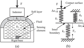
Figure 1. (a) Schematic diagram of the sensor cell contacting an indentor. (b) Schematic diagram of a spring system model for pressure transmission of the sensor structure.
Download figure:
Standard image High-resolution image2.2. Sensing principle
The working principle of the sensor is based on the fluid power transmission between the soft layer and the pressure sensing element. When force is applied on the soft bulge, the bulge deforms, which compresses the fluid in the chamber. Owing to the high bulk modulus, the enclosed fluid is nearly incompressible which leads to effective pressure transmission so that it is sensitive to even tiny compression. The numerical relationship between the volume change of the fluid and the pressure inside is expressed as

where p and p0 are the pressure inside the fluid and the initial pressure, respectively; V and V0 are the volume of the encapsulated fluid under external pressure and the initial volume, respectively; and K is the bulk modulus of the fluid. Due to the small size of the sensor cell, the hydrostatic pressure of fluid by gravity is reasonably omitted.
When contacting an object the working process of the sensor cell is quite complicated. Different from traditional hydraulic devices, the fluid chamber of this sensor cell contains the soft part, which also deforms under the fluid pressure. While the soft layer deforms under external contact to compress the fluid inside, the induced fluid pressure is also reversely loaded onto the soft layer and makes it deform. Thus, there is a coupling effect between the soft layer deformation and the encapsulated fluid compression. To measure the deformation, the stiffness of the soft layer is introduced and defined as the generalized capacity for resisting the deformation of any direction in response to applied force. When contacted by an object, the soft layer can be separated into two parts, which have different boundary conditions. As shown in figure 1(a), the soft layer is divided into the contact section and the non-contact section segmented by the thin dashed lines. The outer boundary of the contact section is constrained by the object while the outer boundary of the non-contact section is free. The inner boundaries of both the contact section and the non-contact section are loaded uniformly by the fluid pressure. Therefore, the contact condition, the stiffness of the soft layer and the stiffness of the compressed fluid jointly determine the boundary profile of the soft layer and finally the pressure change in the fluid.
To further understand the pressure transmission mechanism, the pressure sensing system can be simplified and topologized into a 1D spring system as shown in figure 1. In the spring system, k1, k2 and k3 represent the generalized stiffness of the soft contact section, the soft non-contact section and the compressed fluid, respectively. As the deformation of the soft layer is partially related to the non-contact surface, the stiffness of the soft non-contact section needs to be modified by the non-contact ratio, which is defined as the ratio of the non-contact surface area to the whole outer boundary of the soft layer. The non-contact ratio is denoted by α, ranging from 0 to 1. In figure 1(b), the inner boundary of the soft layer is abstracted to a massless block so that the deformation of the soft layer is condensed into a one-directional displacement. Based on the force equilibrium and deformation compatibility, the following equations can be obtained:


where F and F3 denote the load force and the detected force, respectively;  ,
,  and
and  denote the deformation of each spring, respectively.
From equations (2) and (3), we know that the applied force range depends on the stiffness of the soft layer k1 and possible deformable displacement  , while the force transmission efficiency depends on the value of
  . As the deformation
  is limited by the thickness of the soft layer, the applied force range is largely up to the stiffness of the soft layer k1. To reduce the loss of force load, increasing the contact area or the fluid stiffness or decreasing the stiffness of the non-contact soft layer is implied. The contact area is related to both the shape of the object and the contact force. The fluid stiffness is up to the bulk modulus, which is constant when the fluid type is selected. The stiffness of the soft layer can be reduced by selecting an elastomeric material with smaller Young's modulus. However, as the above-mentioned applied force range is proportional to the stiffness of the soft layer, a lower stiffness means a smaller force range. Thus, a tradeoff of stiffness for the soft layer is required to balance the applied force range and the force transmission efficiency.
2.3. Prototype design and fabrication
According to the conceptual structure mentioned above, a prototype of the tactile sensor array with 3 × 3 sensing elements is designed and fabricated. As shown in figure 2, the prototype mainly consists of five parts: the rigid base, the pressure sensing die, the fluid, the soft layer and the clamp plate. The entire dimensions of the sensor array prototype are 14 mm × 14 mm × 6.5 mm, which meets the limited space requirements of fingertip tactile application.

Figure 2. (a) Schematic view, (b) cross-section view and (c) exploded view of the sensor prototype.
Download figure:
Standard image High-resolution imageFrom bottom to top, the chamber array is sandwiched by the rigid base, the soft layer and the clamp plate tightened by the screws. Each chamber space consists of the cavities in both the rigid base and the soft layer. The rigid base contains 3 × 3 cylindrical cavities with a diameter of 4 mm and depth of 2 mm for each. In addition, in the rigid base, there are twelve M1 threaded holes for screws to tighten the clamp plate so that it guarantees a fine sealability in the interface between the rigid base and the soft layer. The soft layer contains 3 × 3 bulges with a diameter of 3 mm. Inside each bulge there is a cavity with a diameter of 1.5 mm. The detailed sizes are depicted in figure 2.
Each chamber described above is filled with silicone fluid (PMX-200, Dow Corning) with viscosity of 50 cSt. A silicon-based pressure sensing die (SM5108C-060, Silicon Microstructures) is selected as the sensing element for its small size and its cube shape with each edge length of only 0.65 mm, as shown in figure 3(b). In addition, the pressure die is favored for its excellent performance in pressure sensing capability. The full scale pressure sensing range is 413.6 kPa, which produces a typical full scale output of 100 mV with linearity error as 0.07% at 5 V DC power supply at room temperature. Before encapsulation of the soft layer, the pressure die adopted was calibrated on the relationship between its output voltage and the outside pressure, the value of which is 0.25 mV kPa−1. The silicon die is composed of four strain gauges forming a full-bridge circuit with a typical bridge resistance value of 5 kΩ, which improves the sensitivity and enables the elimination of temperature drifting. The pressure die is adhered onto the center of the bottom surface of each chamber using epoxy adhesive (DP 420, Scotch-Weld, 3M). As shown in figure 3(a), in the bottom of each cavity there are five through holes with a diameter of 1 mm. Four of these holes are reserved for fixing the metal pins and the other for fluid entrance. The metal pins are fixed using glass sintering technology to ensure a good seal and electrical insulation between the metal pins and the rigid base. As to the wire connection problems, the pressure die is accessed by the external circuitry through the metal pins. Using ultrasonic wire bonding technology, the four pads of the silicon die are connected to the four metal pins with gold wires.
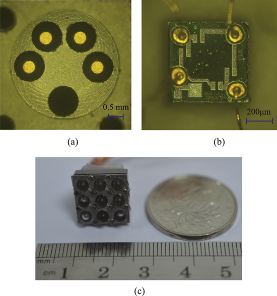
Figure 3. (a) Photo of a cavity of the rigid base with pins mounted. (b) Photo of the pressure sensing die with gold wires connected. (c) Photo of the prototype.
Download figure:
Standard image High-resolution imageBoth the rigid base and the clamp plate were fabricated from stainless steel by traditional machining technologies. As to the soft layer, it was molded from PDMS (Sylgard 184, Dow Corning) with 10:1 of monomer to curing agent. The fabrication steps for the soft layer are shown in figure 4(a). When the major solid parts are ready, the assembling process can be conducted as shown in figure 4(b). The fluid filling process is implemented using a homemade vacuum tank where the sensor array is immersed in silicone fluid, as depicted in figure 4(c). There is a small hole in each chamber, which expels trapped air and lets fluid enter. After filling with fluid, a small steel ball with diameter of 1 mm is inserted into the fluid inlet and then covered by a thin layer of the epoxy adhesive (DP 420, Scotch-Weld, 3M), which plugs possible tiny gaps and confines the silicone fluid inside the chamber. The fabricated prototype of the tactile sensor array is shown in figure 3(c).
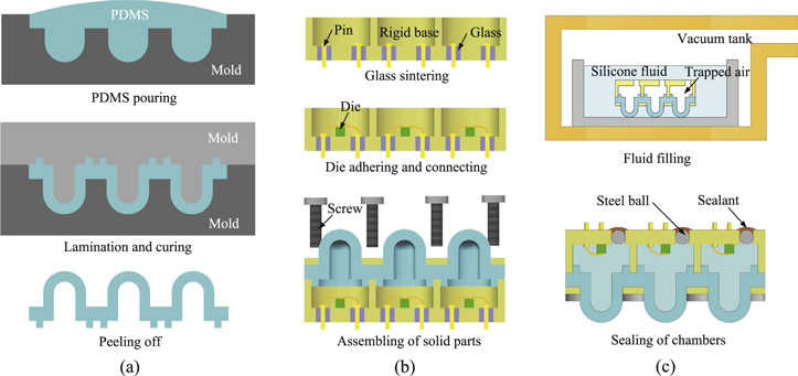
Figure 4. (a) Fabrication of the soft layer. (b) Fixing of solid parts. (c) Filling with silicone fluid.
Download figure:
Standard image High-resolution image2.4. Simulation
The finite element simulation employing COMSOL 5.1 is performed to verify the relationship between the fluid pressure change and the applied force. Considering tactile sensing working at low frequency, the dynamic flow behaviors of fluid in the sealed chamber are ignored to simplify the simulation model. Hence, in the model, a volume related pressure is applied on the inner boundary of the chamber. According to equation (1), the volume of the enclosed fluid is calculated simultaneously for the fluid pressure change. The coupling effect between the fluid pressure and the soft layer deformation is processed through iterative computation. As the structure of each tactile cell is approximate to axial symmetry, a 2D axisymmetric model is established. As shown in figure 5(a), a flat indentor is loaded on the top soft bulge in the sensor model. The parameters set for the model are shown in table 1. The bulk modulus of the silicone fluid refers to the data in [27]. In the simulation, the flat indentor is moved down vertically at a displacement of 0.5 mm with a move step of 0.01 mm, and both the encapsulated fluid pressure and the contact force are calculated at the same time. The linear relationship between the fluid pressure and the contact force is depicted in figure 5(b) with good sensitivity of 119.3 kPa N−1 and good linearity with Pearson'r as 0.998. To analyze the relationship more accurately, the load force is divided into two parts: 0-0.1 N and above 0.1 N with sensitivities 98.8 kPa N−1 and 124.4 kPa N−1, respectively. The results are compared with the experimental tests in the following section.

Figure 5. (a) Model of the sensor cell and the deformation of the soft layer under a loading force of 0.5 N. (b) Relationship between the encapsulated fluid pressure and the indentation force using the finite element method (FEM).
Download figure:
Standard image High-resolution imageTable 1. Parameters for the simulation model.
| Parameter | Value |
|---|---|
| Young's modulus of PDMS | 2 MPa |
| Poisson ratio of PDMS | 0.499 |
| Young's modulus of stainless steel | 200 GPa |
| Poisson ratio of stainless steel | 0.3 |
| Bulk modulus of silicone fluid | 1.05 GPa |
3. Results and discussion
3.1. Test set-up
To study the sensing performance of the tactile sensor under indentation, test experiments were conducted using the set-up shown in figure 6. The sensor prototype is well fixed on a specially designed stage and the rigid base is carefully clamped. Right above one of the sensor cells, a 4 mm diameter circular loading bar with flat bottom surface is mounted onto a load cell (BSLM-3, Bufson Instrument Technology, China), which is linked to a three-axis manual stage (M460P, Newport) through an aluminum alloy accessory. The load cell is used for load force monitoring. Sensing signals from the prototype are processed by the signal conditioning circuits with an amplification factor of 100. In figure 6, nine channels of signal conditioning circuits are established for each sensor cell of the sensor array. A schematic diagram of one channel of the signal conditioning circuit is depicted in figure 7(a) while a schematic diagram of the data acquisition system for nine channels of sensing signals from the sensor array are shown in figure 7(b). The signal conditioning circuit is composed of three parts: the Wheatstone bridge, the zero adjustment and the instrument amplifier. The sensor cell itself contains four resistors to form the Wheatstone bridge. And the initial output signals from the Wheatstone bridge are zeroed before being sent to the instrument amplifier. Both the sensing signal from the conditioning circuit and the load monitoring signal from the load cell are acquired by independent channels of a data acquisition card (USB-6343, National Instruments).
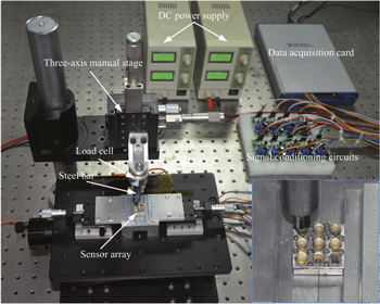
Figure 6. Experimental set-up for indentation tests.
Download figure:
Standard image High-resolution image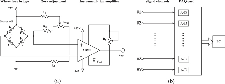
Figure 7. (a) Schematic diagram of one channel of the signal conditioning circuit. (b) Schematic diagram of the data acquisition system for nine channels of sensing signals.
Download figure:
Standard image High-resolution imageAs all cells of the sensor array are separated from each other by the rigid base and the rigid clamp, the crosstalk effects between the adjacent sensor cells are weak enough to be ignored. Considering the above, in this study we focus on the sensing performance of a single sensor cell. Therefore, only the test results from one sensor cell of the sensor array prototype are presented below.
3.2. Indentation tests and results
Based on the experimental set-up described above, indentation tests are conducted to evaluate the sensing performance during load-controlled contact stimulus. The rod loading bar, together with the load cell, is driven by the three-axis stage with revolution, of 0.01 mm in each direction. The loading bar with a flat surface vertically indents the bulge of the sensor cell, and the sensor array is horizontally fixed so that the bottom surface of the sensor array is maintained parallel to the platform.
The indentation tests have two stages to investigate the sensitivity, linearity and hysteresis of the developed sensor. In the first stage, the authors focus on investigating the sensitivity for stimuli near the low-force threshold. The loading bar indents the sensor cell with a force decreased from 0.1 N until the response of the sensor cell is drowned in noise by carefully adjusting the indentation displacement. The original point for the indentation movement is set at the location where the force is loaded as 0.1 N. In the second stage, the load force ranges from 0 to 1.6 N. The testing is conducted so that the loading process increases the force by 0.2 N at each step from 0 to 1.6 N, while the unloading process decreases the load force by 0.2 N at each step from 1.6 N to 0. The test processes are repeated five times. Considering the sensing fingertip consisting of nine sensor cells, the total mechanical stimulus is up to 14.4 N.
Figure 8(a) shows the force loading signal under 0.1 N, the original measured signal and measured signal filtered by the FFT filter method. Both the constant loading duration and the interval of force load are about 25 s. The first step of the signal responds to the force loading of 0.1 N, followed by the steps with indentation depth decreasing by 0.01 mm compared to the previous one. After the thirteenth step (0.12 mm away in depth from the origin), the response is drowned in the signal noise, which is far from distinguishable. The smallest step of the filtered signal is 8 mV, resulting from an applied force of 5 mN, which can be thought of as the minimum detectable threshold of the sensor cell. Figure 8(b) indicates the linear relationship between the measured voltage and the applied force under 0.1 N, with Pearson's r as 0.999 and sensitivity as 15.77 mV N−1 (without amplification). The rapid response to the loading and unloading steps is clearly shown in the signal waveform, which implies the good dynamic characteristic of the sensor.

Figure 8. (a) Force loading signal, measured signal and filtered signal of the sensor cell when the applied force is under 0.1 N. (b) Relationship between the measured voltage of the sensor cell and the applied force under 0.1 N.
Download figure:
Standard image High-resolution imageFigure 9 shows the measured voltage change of one sensor cell through applied force between 0 and 1.6 N in both the loading and unloading processes. The results indicate good linearity performance with Pearson's r as 0.998 and high sensitivity as 19.9 mV N−1 (without amplification). In addition, the repeatability errors for both the loading and unloading processes are small so that the largest error is 3.41% of the full scale output. The hysteresis can be elicited by comparison of the measured signals in loading and unloading processes; and the largest is found at 0.8 N with a discrepancy of 3.34%. Table 2 gives the detailed repeatability errors and hysteresis errors for the five tests.
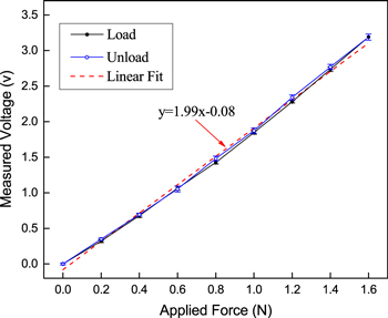
Figure 9. Relationship between the measured voltage and the applied force of one sensor cell from the indentation tests.
Download figure:
Standard image High-resolution imageTable 2. Repeatability and hysteresis error.
| Repeatability error | Repeatability error | Hysteresis error | |
|---|---|---|---|
| Force (N) | for loading (%) | for unloading (%) | (%) |
| 0 | — | 0.95 | 0.54 |
| 0.2 | 1.71 | 1.37 | 2.26 |
| 0.4 | 1.82 | 1.60 | 1.99 |
| 0.6 | 2.08 | 3.18 | 1.65 |
| 0.8 | 1.90 | 2.64 | 3.19 |
| 1.0 | 1.86 | 3.41 | 2.28 |
| 1.2 | 1.35 | 2.67 | 3.34 |
| 1.4 | 2.72 | 3.26 | 2.73 |
| 1.6 | 3.23 | — | — |
3.3. Discussion
It is meaningful to compare the experimental results with the previous FEM results. As the sensitivity value of the pressure die is 0.25 mV kPa−1, the sensitivities for the low and high force load can be converted into 63.1 kPa N−1 and 79.6 kPa N−1, respectively. According to the FEM work, the sensitivities are 98.8 kPa N−1 and 124.4 kPa N−1, respectively. Therefore, the sensitivity variations from low force to high force are exactly the same, which is a 26% increase for both. The possible reason for the sensitivity change is that the soft layer is easy to deform and be compressed under low force but has slightly further deformation under high force. Thus, the soft layer has a major role in resisting low forces while the fluid has a major role in resisting high forces.
To further verify the positive effects of the fluid, we set up another device in which pressure die is directly covered with a 5 mm thick silicone layer, as shown in figure 10. The pressure die is adhered onto the rigid base with gold wires connected to the outside circuit. The indentation tests were implemented to compare with the sensing performances of the proposed sensor. In the tests, the diameter of the rod indentor is selected as 2 mm because the gold wires are fragile and a larger indentor would easily break those wires. To avoid possible damage, the indentation force is from 0 to 0.5 N. Three aspects of the two devices are to be compared. First, the comparison of normalized test results is depicted in figure 11(a), which shows that the proposed sensor reduces by 25.6% the hysteresis values. Second, to compare the sensing stabilities, we conduct the experiments with the force load staying at 0, 0.25 N and 0.5 N for about 30 s for both the proposed sensor and the fully silicone-covered device. As shown in figure 11(b), the measurement signals are normalized for easier comparison. The results indicate that the fully silicone-covered device suffers from the stress relaxation problem of soft silicone, which leads to a signal drift of 6% for 50s when the force load is at 0.5 N. By contrast, the proposed sensor maintains stable output with very little signal drift. Third, for the pressure transmission efficiency, we can convert both the contact force and the output voltage into pressure values. The pressure transmission ratio is then calculated as 56.2% for the proposed sensor compared with 21.4% for that with direct elastomer layer, which indicates an effective improvement of sensitivity. Therefore, this indicates that using fluid to replace some part of the silicone layer will effectively reduce the negative effects of soft materials and improve the sensing ability for the sensor cell.
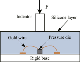
Figure 10. Schematic diagram of the indentation test for pressure die directly covered with a silicone layer.
Download figure:
Standard image High-resolution image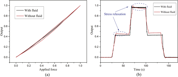
Figure 11. Comparison results of the indentation tests for the proposed sensor and pressure dies directly covered with a silicone layer. (a) Comparison of hysteresis between the loading and unloading processes. (b) Comparison of the stress relaxation phenomenon.
Download figure:
Standard image High-resolution imageIn this work, we focused on investigating properties of the proposed sensor structure for normal contact force, thus the tests are all related to vertical indentation. In principle, the sensor should also respond to lateral stimulation. Additional load tests with lateral force ranging from 0 to 1 N were conducted and the results are shown in figure 12. Compared with the performance under vertical indentation, the response to lateral force has smaller sensitivity as 14.2 mV N−1 (without amplification). This is likely because the deformation of the sensor structure is asymmetric under a lateral force and that some parts of the soft layer are stretched while other parts are compressed, which limits the function of fluid compression and weakens the pressure transmission. Thus, for better performance with both vertical and lateral force loads, it is necessary to make further improvements to the sensor structure to guarantee effective fluid compression all the time. For a single sensing cell, it is difficult to distinguish between a lateral force and a vertical force. However, it is feasible to form a new sensor cell containing four sensing elements using a proper structure to enable 3D force detection, which has been realized in much past research.

Figure 12. Relationship between the measured voltage and the applied lateral force on one sensor cell.
Download figure:
Standard image High-resolution image
4. Conclusion
In this study, a novel tactile sensor structure combining the encapsulated fluid and the soft layer was proposed. A compact prototype with a 3 × 3 sensor array and dimensions of 14 mm × 14 mm × 6.5 mm was presented to show the capability of tactile sensing for fingertip application. A commercial tiny pressure die was integrated into the sensor cell to detect fluid pressure changes. The fabrication of the rigid base and the compliant PDMS layer, and the encapsulation process of the prototype, were easily reached by currently available methods. To illustrate the working principles of the sensor structure, an analytic model based on the spring system was established and followed by a FEM simulation. The FEM work correctly indicated the sensitivity change from low force to high force by 26%. Testing results showed that the sensor cell has high sensitivity of 19.9 mV N−1 in the range of interest from 0 to 1.6 N, high repeatability with repetitive error of 3.41% and low hysteresis with a discrepancy error of 3.34%. The detectable low force threshold is 5 mN, and the total sensing capacity can be up to 14.4 N on a fingertip integrating the developed sensor array. Therefore, this sensor cell structure effectively attenuates the negative impacts related to the soft skin layer. To sum up, for task related requirements of prosthetic hands, the proposed tactile sensor structure performs well in comprehensive aspects with high reliability, low hysteresis and good force sensing ability while achieving balance between a compliant contact surface and sensing element protection.
In future work, the authors will focus on improving the spatial resolution of the sensor array by further innovation of the elastomeric layer structure and developing an effective algorithm. The investigation of other tactile sensing capabilities such as slip detection and texture discrimination will be also carried out.
Acknowledgments
This work is supported in part by the National Basic Research Program of China under Grant 2011CB013303 and the Science Fund for Creative Research Groups of National Natural Science Foundation of China under Grant 51521064.