
Abstract
A theoretical study of the propagation of left-hand polarized shear Alfvén waves in spatially decreasing magnetic field geometries near the EMIC resonance, including the spectrum and amplitude of the mode converted EMIC waves and the pitch angle scattering of relativistic electrons transiting the resonant region, is presented. The objective of the paper is to motivate an experimental study of the subject using the UCLA LAPD chamber. The results are relevant in exploring the possibility that shear Alfvén waves strategically injected into the radiation belts using either ionospheric heating from ground based RF transmitters or injected by transmitters based on space platforms can enhance the precipitation rate of trapped relativistic electrons. Effects of multi-ionic composition are also investigated.
Export citation and abstract BibTeX RIS
1. Introduction
Electromagnetic ion cyclotron (EMIC) waves are left-hand polarized shear Alfvén waves propagating parallel to the ambient magnetic field with frequency approaching the ion cyclotron frequency. They are often found in the radiation belts and are considered primary candidates for precipitation of MeV electrons trapped in the belts. The surprising strength of the interaction of waves with frequency  much smaller than the electron cyclotron frequency
 with relativistic electrons can be appreciated by referring to the dispersion relation of low frequency waves propagating parallel to the ambient magnetic field
  in multispecies plasma, given by
where  and
and  are the ion plasma and cyclotron frequencies, respectively, of ion species
  and
and  and
and  are the electron plasma and cyclotron frequencies. (The other symbols have their usual meaning.)
Figure 1 shows an example of this dispersion relation for a plasma with a mixture of hydrogen, helium and oxygen ions such as encountered in the radiation belts. Notice that

As a result there will be a wavenumber range close to the ion resonance where electrons with energy  will satisfy the anomalous cyclotron resonance condition for pitch angle scattering

Since  the condition given by equation (3) reduces to a wavelength condition given by

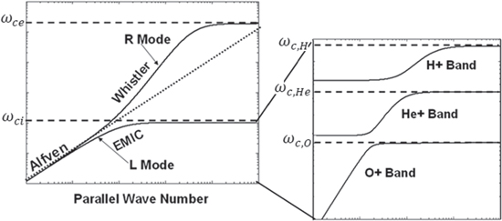
Figure 1. EMIC dispersion relation for a multi-ionic plasma including hydrogen (H), helium (He) and oxygen (O) ions.
Download figure:
Standard image High-resolution imageIn most of previous work on the subject it was assumed that the EMIC waves are excited by unstable distributions of ring current ions both inside and outside the plasmapause and propagate in regions localized in longitude. The electrons drifting eastward in the Earth's magnetic field encounter the localized waves and are scattered in pitch angle with scattering rate that depends critically on the wave amplitude, frequency and chirping rate of the EMIC waves (Summers et al 2007, Omura et al 2010, Morley et al 2010, Engebretson et al 2015, Kubota et al 2015). In this paper we want to propose that EMIC waves with controlled bandwidth and chirping rate can be generated by mode conversion of shear Alfvén waves propagating along the magnetic field lines when they encounter the EMIC cyclotron resonance. Such a possibility was addressed recently by Shao et al (2009) who proposed shear Alfvén waves generated by ionospheric heating can create regions of strong EMIC waves when they encounter the O+ cyclotron resonance at altitude between 1000 and 2000 km. Alternatively such waves can be artificially injected at the appropriate regions from space-based transmitters. The underlying mode conversion physics parallels the 'magnetic beach' experiments and theory conducted by, among others, Stix (1958), Stix and Palladino (1958), and Roberts and Hershkowitz (1992), and occurs when a left-hand polarized shear Alfvén wave propagates parallel to a weakening magnetic field.
The objective of this paper is to motivate a laboratory experiment to study mode conversion of shear Alfvén waves in a mirror geometry, such as it occurs in the radiation belts, and determine the pitch angle scattering rate of energetic electrons interacting with the waves through the anomalous cyclotron resonance interaction by controlling the parameters of the injected shear Alfvén waves. Such an experiment can ideally be conducted at the UCLA LAPD device that has already been the site of numerous experimental studies of kinetic shear Alfvén waves with multispecies ion plasmas in mirror geometries (Vincena et al 2001, 2010, 2011, 2013, Farmer and Morales 2013). These studies focused on the kinetic Alfvén wave injection and the resultant ion heating and ion–ion hybrid resonant effects. It should be noted that pitch angle scattering of energetic electrons have been studied using whistler waves (Van Compernolle et al 2014) and Alfvén waves (Wang et al 2012, 2014).
In this paper we investigate the wave propagation of EMIC waves near cyclotron resonances, including the resultant wave spectra near the singularity and the pitch angle scattering of relativistic electrons injected in the turbulent region. The linear Hall-MHD model with an inhomogeneous magnetic field is presented in section 2, where analytic solutions (Stix 1960, 1992) of the waveform near cyclotron resonances are discussed for waves propagating parallel to the magnetic field. The analytic results are compared to numerical simulations in section 3. In section 4, the analytic solution for the wave magnetic field is used to derive the pitch angle diffusion coefficient and compute the scattering of relativistic electrons for typical UCLA LAPD parameters. Finally, conclusions are drawn in section 5.
2. Mathematical model
To study the propagation of EMIC waves in spatially varying plasma, we use the cold Hall-MHD model involving the linearized ion momentum equation for ion species  with charge
  and mass

and the electron momentum equation for the inertialess electrons

where  and
and  are ion and electron damping rates due to collisions. The equations of motion are coupled with Ampère's and Faraday's laws,

and

respectively, and where quasineutrality requires that  where
where  is the electron number density.
2.1. Propagation parallel to the magnetic field
As the EMIC wave approaches a cyclotron resonance, its parallel wave vector component gradually increases. For an L-polarized wave with frequency  propagating parallel to
  such that
 ![${\bf{E}}={\rm{Re}}[E(z)(\hat{{\bf{x}}}-{\rm{i}}\hat{{\bf{y}}}){{\rm{e}}}^{-{\rm{i}}\omega t}]$](https://content.cld.iop.org/journals/0741-3335/59/10/104003/revision2/ppcfaa8100ieqn21.gif) and similarly for
and similarly for 
 and
and  equations (5)–(8) turn into scalar complex valued equations for the envelopes,


and

respectively. Eliminating 
 and
and  from equations (9)–(12), the equation for the electric field envelope for can be written
The cyclotron and plasma frequencies vary in space depending on the profiles of the number densities and the magnetic field. In the absence of collisions, resonances occur where  so that the expression in parenthesis on the right-hand side of equation (13) diverges, while ion–ion hybrid cutoffs occur when this expression vanishes, introducing stop bands between the ion cyclotron resonances (e.g. Perkins 1977, Summers and Thorne 2003). In an inhomogeneous magnetic field, the ion–ion hybrid cutoffs represent reflecting layers for EMIC waves as they propagate towards converging magnetic fields and their wavelengths increase, while the ion cyclotron resonances represent absorbing layers, where the EMIC wavelength decreases and the wave energy is converted to kinetic energy of the ions. The EMIC waves are expected to pitch angle scatter electrons most efficiently near the short-wavelength EMIC resonances where the resonance condition (4) can be fulfilled, while the ion–ion resonance cutoffs occur at long wavelengths with no efficient electron pitch angle scattering.
2.2. Analytic solutions near resonance
To obtain analytic solutions of the wave profiles near cyclotron resonances, we assume a diverging ambient magnetic field decreasing with  Near the location of the ion cyclotron resonance,
  where
where  we can expand
  for
for  where
where  and
and  is the length-scale of the decreasing magnetic field. Neglecting collisions, we then have from equation (13)

where  We note that
  is oscillatory in space for
  and evanescent for
  The spatial profile of the wave near resonance depends only on the local length-scale of the magnetic field and the ion plasma frequency, and hence on the number density of the resonant ion species. The WKB approximation can be used in a slowly inhomogeneous plasma, but it breaks down close to resonances, where the plasma dielectric function varies more rapidly than the local wave vector (Stix 1960, 1992). The WKB solution would predict a highly oscillatory solution with infinitely many wavelengths near the resonance, which is generally not the case.
We next for simplicity assume that  is constant. The electric field for an incoming wave propagating in the positive
  direction, is given by the solution of equation (14) as (Stix 1960, 1992)
where  and
and  are Bessel functions of the first and second kind, and
  is the modified Bessel function of second kind, of order
  The wave magnetic field is obtained from Faraday's law (12) as
where we denoted  The ion quivering velocity is obtained from the ion momentum equation (9) as

which, using  gives
gives
with 
Figure 2 shows the spatial profiles of 
 and
and  As noted by Stix (1960, 1992) there is a decrease of
  near resonance, but the electric field remains finite,
  at
at  For the wave magnetic field, there is a logarithmic divergence of the amplitude near
  The ion quivering velocity
  has a
has a  singularity near the resonance, implying that most of the wave energy density near the resonance is in the kinetic energy density
  of the ions. Thus, in general the EMIC wave propagates towards the resonance where it absorbed by the acceleration of ions. It should be noted that dissipative effects such as collisions and ion cyclotron damping (and possibly nonlinear effects) will prevent infinite amplitudes at the resonance. In the derivation of the analytic solutions (Stix 1960, 1992), a small damping was kept as a mathematical tool making
  complex valued, to avoid the singularity at the resonance.
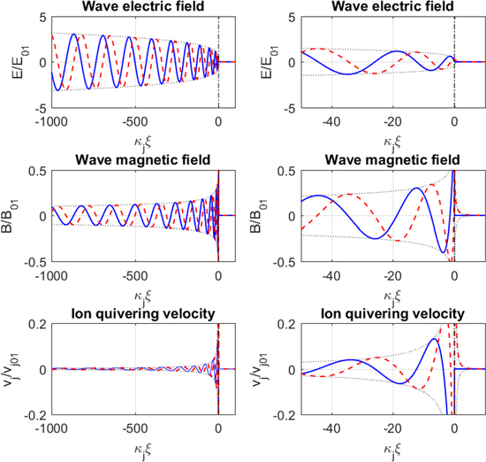
Figure 2. The electric field, magnetic field, and ion quivering velocity (top to bottom panels), showing real parts (blue solid lines) and imaginary parts (red dashed lines) near the resonance layer at  for a linearly decreasing magnetic field. The right-hand column shows a close-up near the resonance. The EMIC wave is evanescent and the amplitude decreases exponentially with distance for
Download figure:
Standard image High-resolution image3. Simulations of EMIC wave propagation
To assess the analytic solution for the wave magnetic field, we carry out simulations of EMIC propagation in laboratory plasma. Some details of the numerical two-ion model is given in appendix A. We use plasma parameters and dimensions relevant for the UCLA LAPD device. Figure 3 shows the propagation of EMIC waves in single ion species plasmas with a decreasing magnetic field along the  -axis (see figure 3(a)), using singly charged neon (Ne) and helium (He) ions with a homogeneous plasma density of
  (see figure 3(b)). To study the wave propagation near resonance in the Ne plasma, an L-polarized wave is excited at
  with frequency
 which equals
  at
at  (figure 3(c)). In the He plasma, a wave with frequency
 is launched, which also equals
  at
at  (figure 3(d)). The EMIC wave in both cases approaches the resonance layer
  (indicated with red dashed lines) where the local magnetic field has decreased to
  and only weak excitations are seen beyond the resonant layer. The local magnetic field length-scale
  at the resonance layer, and the ion plasma frequencies
  and
and  give
give  and
and  reflecting the more rapid spatial oscillations near the He resonance in figure 3(d) compared to the Ne resonance in figure 3(c).

Figure 3. The propagation of EMIC waves in single ion Ne and He plasmas, showing (a) the axial magnetic field, (b) particle number densities, with  and with
 in panel (c) and
 in panel (d). L-polarized EMIC waves are excited at
  with frequency
 (panel (c)) and
 (panel (d)), which respective equal
  and
and  at
at  where
where  (dashed horizontal lines). For clarity, the horizontal axes have been enhanced in panels (c) and (d).
Download figure:
Standard image High-resolution imageIn figure 4, the same magnetic field profile as in figure 3 is used, but with spatially varying ion number densities in a mixture of Ne and He ions and with a spatially increasing He number density along the  -axis. Ion cyclotron resonances occur at
  (same as in figure 3) for the transmitted frequencies
  and
and  and an ion–ion hybrid cutoff at
  (see figure 4(d)) for
  In the latter case, the source at
  is within the evanescent region, and the EMIC waves must tunnel through the evanescent region to become propagating waves for
  It should be noted that while EMIC waves can tunnel through a small evanescent region in laboratory plasma, the effect would be more significant in the ionosphere due to much larger gradient length-scales.

Figure 4. The propagation of EMIC waves in two-ion Ne-He plasma showing (a) the axial magnetic field, (b) particle number densities, with  with spatially varying ion number densities keeping
  L-polarized EMIC waves are excited at
  with frequencies
 (panel (c)) and
 (panel (d)) which respectively equal
  and
and  at
at  where
where  (horizontal dashed lines). The ion–ion hybrid cutoff
  is at
is at  for
for  (panel (d), dashed–dotted line). For clarity, the horizontal axes have been enhanced in panels (c) and (d).
Download figure:
Standard image High-resolution image4. Pitch angle diffusion of relativistic electrons
While the magnetic moment of a relativistic electron (e.g. Walt 1994, Öztürk 2016)  is nearly conserved in a slowly varying magnetic field, hydromagnetic waves can resonantly scatter and break the conservation of the magnetic moment, leading to an increased precipitation of mirror contained electrons. Here,
  is the relativistic gamma factor,
  is the speed of the electron, and
  is the magnitude of the velocity of the electron perpendicular to the magnetic field. Models exist for the pitch angle scattering of charged particles by broadband hydromagnetic waves in the Earth's dipole magnetic field (Lyons and Williams 1984, Summers and Thorne 2003, Shao et al 2009). The question is how efficiently the EMIC waves near cyclotron resonances pitch angle scatter relativistic electrons. The Doppler resonance condition between a relativistic electron and an EMIC wave propagating parallel to the magnetic field is (e.g. Summers and Thorne 2003)
  where
where  is the parallel component of the electron's velocity and
  is the pitch angle. Omitting the
  -term, which is justified since
  for EMIC waves, the resonance condition can be written

The spatially varying wave magnetic field (see figure 2) may interact resonantly with relativistic electrons where the EMIC wave locally fulfills the resonance condition (19). To derive a diffusion coefficient for the pitch angle scattering of relativistic electrons, we first calculate the spatial Fourier transform of the wave magnetic field (see appendix B),
where  is the sine integral (Abramowitz and Stegun 1964). It holds that that
  for
for 
 for
for  and
and  for
for  A good approximation of equation (20) for
  is therefore

Hence, an EMIC wave which is monochromatic in time has a broadband spatial spectrum near the cyclotron resonance. The scattering of charged particles due to broadband electromagnetic waves can be treated with quasilinear theory (Melrose 1980, Steinacker and Miller 1992). Summers and Thorne (2003) give the pitch angle diffusion coefficient on the form

where  is the background magnetic field energy density, and
  is the wave magnetic field spectral density normalized such that
  where
where  is the spatially averaged wave magnetic energy density. Assuming a spatial average over a domain
  much larger than the EMIC wavelength, we have the spectral density

Using equation (23) in equation (22) then gives the pitch angle diffusion coefficient

with  given by equation (20). Using instead the approximate expression (21) in equation (24) gives

for  and
and  for
for  and where the resonance condition (19) was used in the last step in equation (25). For multi-MeV electrons, we can use
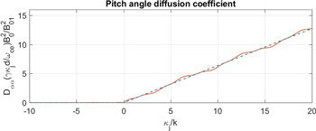
  The diffusion coefficient given in equations (24) and (25) are plotted in figure 5 as solid and dashed lines, respectively. It is seen that
  to a good approximation grows linearly with positive
  and is negligibly small for negative
  The asymmetry of the diffusion coefficient with respect to the sign of
  reflects that the L-polarized EMIC wave interacts resonantly with electrons propagating in the same direction as the wave, but not with electrons propagating in the opposite direction.
Figure 5. Normalized pitch angle diffusion coefficient  (solid line) as a function of
  where
where  and
and  is given by equation (20) with
  being the pitch angle. Efficient pitch angle diffusion occurs only for
  i.e. for electrons propagating in the same direction as the EMIC wave. The solid line is given by the expression (24) while the dashed line shows the approximation (25).
Download figure:
Standard image High-resolution image
For mirror-contained electrons, we can estimate the effective domain length  where
where  is the bounce period, which inserted into equation (25) gives the bounce-averaged pitch angle diffusion coefficient

Using equation (26), the spread in pitch angle after time  may roughly be estimated as

It is desirable to express the diffusion coefficient (26) and pitch angle spread (27) in terms of the local wave magnetic field amplitude  where the resonant wave-particle interaction takes place. Using large argument expansions of the Bessel functions
  and
and  in equation (16) gives
  for
for  The phase of the EMIC wave varies approximately as
  and hence the local wavenumber can be taken as
  Resonant wave-particle interaction takes place where
  i.e. where
  This gives
  solving for
  and inserting the result into equations (26) and (27) gives

and

respectively, where  is evaluated in space at
As an application of the above results we consider injecting 2 MeV electrons (
 ) with a pitch angle of
  giving the parallel velocity
  in the UCLA LAPD chamber under the conditions discussed previously (see figures 3 and 4). The results are summarized in table 1. The high-energy electrons with large pitch angles could for example be injected via electron cyclotron resonance heating (ECRH), in a similar manner as was done by Wang et al (2012, 2014). To mirror contain these electrons, the magnetic field should be significantly increased near both ends (both the high-field and low-field) of the device to form 'magnetic plugs' (not shown in figures 3 and 4). The condition for containment is
  for the mirror ratio
  For a magnetic field of
  near the EMIC resonance layer (see figure 3), it is thus required that
  to mirror contain an electron with pitch angle
  The non-relativistic electron cyclotron frequency is
  and the condition (19) gives a resonant wavenumber
  For mirror contained electrons in the UCLA LAPD device (axial length
  m), the bounce time back and forth once in the mirror field would be
  Using the parameters in figure 3, with
  and
and  gives
gives  and
and  and assuming a large wave amplitude such that
  (e.g. Carter et al 2006, Auerbach et al 2010, Howes et al 2012, Dorfman and Carter 2013, 2015, 2016) would give (see equation (28))
  for the Ne case and
  for the He case. After
  (about 5 bounces back and forth) the pitch angle spread (equation (29)) would be
  rad for the Ne case and
  for the He case. The typical lifetime of a relativistic electron depends on the mirror ratio of the experiment, the initial distribution of the electrons, etc. As a crude estimate, it can be assumed that the electrons have a significant probability to being scattered into the loss cone when the
  rad. Using
  in equation (29) and solving for time, the estimated lifetime is

Table 1.
The pitch angle scattering of relativistic electrons by EMIC waves with parameters for Ne and He laboratory plasma (see figure 3) relevant to the UCLA LAPD chamber. For 2 MeV electrons having the initial pitch angle  and EMIC waves of amplitude 1% of the background magnetic field, the typical lifetime is of the order 1 ms or less.
| Species |

|

|

|

|

|

|

|
|---|---|---|---|---|---|---|---|
| Ne | 0.1 | 0.01 | 16 | 30 |

|

|
1 |
| He | 0.1 | 0.01 | 16 | 153 |

|

|
0.2 |
This gives the lifetime  ms for the Ne case and
  ms for the He case. It should be noted from equation (30) that the lifetime scales as the inverse square of the wave amplitude, and from the definition
  (see equation (14)) the lifetime is inversely proportional to the length-scale
  of the magnetic field at the ion cyclotron resonance, i.e. larger
  leads to more efficient electron scattering. The locations of the strongest resonant electron-wave interaction is
  for the Ne case and
  for the He case. Hence, the resonant interaction occurs at
  for the Ne case (see figure 3(c)), and
  for the He case (see figure 3(d)). Both cases fit well in an experiment.
It is interesting that Wang et al (2012, 2014) in their experiment observed efficient scattering of electrons by right-hand polarized Alfvén/whistler waves, which they attributed to the interference between the whistler wave and the electron's azimuthal grad-B drift motion also occurring in the right-hand direction, but no efficient electron scattering by left-hand polarized EMIC waves. However, their launched EMIC wave frequency was significantly lower than the ion cyclotron frequency, resulting in a wavelength too long to resonantly pitch angle scatter the electrons.
The ultimate goal is to model electron scattering by EMIC waves in the ionosphere. As an example of parameters of the Earth's ionosphere at an altitude of 2000 km, we take the magnetic field  T giving the electron cyclotron frequency
  and the number density of hydrogen ions
  corresponding to the hydrogen plasma frequency
  We again consider 2 MeV electrons, with
  and
and  Using a typical local magnetic field length-scale
  would give
  while the resonance condition (19) gives the resonant wavenumber
  so that
  A typical relativistic electron at an altitude of 2000 km near the equator has a bounce period of the order
  (e.g. Hess 1962). Taking the EMIC wave magnetic field
  gives (see equation (28))
  and (see equation (29))
  (with
(with  in seconds). The typical lifetime of an electron can be taken as when it has been pitch angle deflected to
  rad, which is reached when
  (
( h). Taking into account a similar degree of pitch angle scattering at the conjugate hemisphere would decrease the lifetime a factor two to
  (
( h). The resonant interaction between the electrons and EMIC wave would take place at a distance
  away from the EMIC resonance layer. There will also be a longitudinal grad-B drift of the electrons with a revolution of the order of an hour. If the EMIC waves are present only in localized regions, the drift-averaged diffusion coefficient may be a few orders of magnitude smaller than
  and the lifetime correspondingly longer (e.g. Summers and Thorne 2003).
5. Conclusions
The propagation of EMIC waves near the cyclotron resonances and the pitch angle scattering of relativistic electrons have been studied theoretically. Multi-ion plasma introduce cyclotron resonances at locations where the wave frequency matches the respective ion cyclotron frequency, and in addition ion–ion hybrid cutoffs where the wave frequency matches the ion–ion resonance frequency. Due to the inhomogeneous magnetic field and rapidly spatially changing wavelength near a cyclotron resonance, a monochromatic (in time) EMIC wave gives rise to a broadband spectrum of waves in space, where relativistic electrons are resonantly pitch angle scattered by the EMIC wave when the local wavenumber fulfills the electron cyclotron resonance condition. Simple expressions for the pitch angle diffusion coefficient are derived using the spatial profile (Stix 1960, 1992) of the wave magnetic field near an ion cyclotron resonance. The theory is relevant to laboratory plasmas such as the UCLA LAPD experiment, where a typical lifetime for a mirror-contained relativistic electron is predicted to be of the order of a millisecond using an EMIC wave magnetic field of the order 1% of the ambient magnetic field. Ultimately the application of the theory is to mirror contained electrons in the Earth's ionosphere, where EMIC waves can pitch angle scatter energetic electrons near the EMIC resonance regions.
Acknowledgments
This work was supported by the MURI grant FA95501410019. B E gratefully acknowledges the hospitality and support of University of Maryland, where part of this work was carried out, as well as support from the EPSRC (U K) grant EP/M009386/1. Discussions with Drs W Gekelman and S Vincena, and a critical reading of the manuscript by G Milikh, are very much appreciated. Simulation data supporting the figures can be found at http://doi.org/10.15129/3878b808-70e6-4d45-b3b3-972cb08ce4b9.
Appendix A.: Numerical multi-ion model
A collisional Hall-MHD model was developed by Eliasson et al (2012) (see also Sharma et al (2016) for polar coordinates), where plasma conductivities and dielectric constants were derived from the electron and ion momentum equations. We here slightly modify the formulation of Eliasson et al (2012) to include multiple ion species. Introducing the vector and scalar potentials  and
and  through
  and
and  with the Weyl (or temporal) gauge
  we have

which effectively replaces Faraday's law. For two-ion species, we have the momentum equations

and

where we denoted  and
and  and
and  and
and  are ion-neutral collision frequencies. The electric field is given by the electron momentum equation with inertialess electrons,

where we denoted  and
and  is the electron-neutral collision frequency. The electron velocity is obtained from Ampère's law as
together with the quasineutrality condition  The displacement current has been neglected in equation (15) with the assumption that the wave speed is much smaller than the speed of light. In the numerical examples, collisions are neglected, hence
The external current source  is employed to inject circularly polarized waves into the plasma by a left-hand rotating current source. We use the divergence-free external current source
where  the peak amplitude of the current density, and
  and
and  is the width and axial position of the source. We use
 and
and  in the simulations. Equations (A1)–(A6) are solved numerically, using a simulation box with dimensions—
 and
and  which is close to the dimensions of the UCLA LAPD chamber. The simulation domain is resolved on a uniform numerical grid with 20 intervals in the x-direction and 400 intervals in the y-direction. For simplicity, periodic boundary conditions are used in the
  -direction while reflecting boundaries
  and
and  are used at
  and
and  Spatial derivatives with respect to x are calculated using a pseudo-spectral method while
  -derivatives are approximated by centered 2nd-order difference approximations. A standard 4th order Runge–Kutta scheme is used to advance the solution in time, with a time-step of
  It should be noted that equation (13) can be derived from equations (A1)–(A5) using
  and the assumption that all time-dependent quantities are proportional to
Appendix B.: Integral relations for the Fourier transform of the magnetic field
In calculating the Fourier transform (21) of the magnetic field in (17), use were made of the following integral relations for  (and
(and  ):
):


where  is the cosine integral of argument
  (Abramowitz and Stegun 1964). For
  a temporary substitution
  with
with  was made to evaluate the integrals, followed by a back-substitution