
Abstract
Objective. Beam current transformers (BCT) are promising detectors for real-time beam monitoring in ultra-high dose rate (UHDR) electron radiotherapy. However, previous studies have reported a significant sensitivity of the BCT signal to changes in source-to-surface distance (SSD), field size, and phantom material which have until now been attributed to the fluctuating levels of electrons backscattered within the BCT. The purpose of this study is to evaluate this hypothesis, with the goal of understanding and mitigating the variations in BCT signal due to changes in irradiation conditions. Approach. Monte Carlo simulations and experimental measurements were conducted with a UHDR-capable intra-operative electron linear accelerator to analyze the impact of backscattered electrons on BCT signal. The potential influence of charge accumulation in media as a mechanism affecting BCT signal perturbation was further investigated by examining the effects of phantom conductivity and electrical grounding. Finally, the effectiveness of Faraday shielding to mitigate BCT signal variations is evaluated. Main Results. Monte Carlo simulations indicated that the fraction of electrons backscattered in water and on the collimator plastic at 6 and 9 MeV is lower than 1%, suggesting that backscattered electrons alone cannot account for the observed BCT signal variations. However, our experimental measurements confirmed previous findings of BCT response variation up to 15% for different field diameters. A significant impact of phantom type on BCT response was also observed, with variations in BCT signal as high as 14.1% when comparing measurements in water and solid water. The introduction of a Faraday shield to our applicators effectively mitigated the dependencies of BCT signal on SSD, field size, and phantom material. Significance. Our results indicate that variations in BCT signal as a function of SSD, field size, and phantom material are likely driven by an electric field originating in dielectric materials exposed to the UHDR electron beam. Strategies such as Faraday shielding were shown to effectively prevent these electric fields from affecting BCT signal, enabling reliable BCT-based electron UHDR beam monitoring.
Export citation and abstract BibTeX RIS

Original content from this work may be used under the terms of the Creative Commons Attribution 4.0 licence. Any further distribution of this work must maintain attribution to the author(s) and the title of the work, journal citation and DOI.
1. Introduction
Radiotherapy has long been a cornerstone in the treatment of various malignancies, offering a non-invasive approach to target and eradicate tumor cells. Over the years, advancements in technology and techniques have sought to maximize the therapeutic ratio by enhancing tumor control while minimizing damage to surrounding normal tissues. One of the most recent and potentially transformative advancements in this direction is the discovery of the FLASH effect. The FLASH effect refers to the observation that ultra-high dose rate (UHDR) irradiation, delivered at rates above 40 Gy/s, can achieve equivalent tumor control while substantially reducing normal tissue toxicity (Favaudon et al 2014, Bourhis et al 2019, Esplen et al 2020). This phenomenon has been observed across various pre-clinical models, including invertebrates, rodents, and larger mammals (Schüler et al 2017, Vozenin et al 2019). The underlying mechanisms for the FLASH effect are still under investigation, but hypotheses include differential oxygen consumption (Weiss et al 1974, Montay-Gruel et al 2019, Adrian et al 2020), enhanced DNA repair in normal tissues (Liew et al 2021, Friedl et al 2022), and alterations in the immune response (Jin et al 2020, Bertho et al 2023). While the FLASH effect has been observed for photons, electrons and protons (Hughes and Parsons 2020, Zhang et al 2020, Kim et al 2021, Montay-Gruel et al 2022), most research evidence stems from MeV electron beams (Schüler et al 2022). This is due to the wide range of machines capable of generating UHDR electron beams including dedicated accelerators, converted conventional linear accelerators and intraoperative radiotherapy machines (Vozenin et al 2019, Moeckli et al 2021). Electron UHDR radiotherapy consequently represents the current reference for clinical transfer of FLASH radiotherapy in pre-clinical and clinical settings (Bourhis et al 2019, Schüler et al 2022, Vojnovic et al 2023).
A significant challenge in the translation of UHDR radiotherapy is our currently limited ability to accurately measure key irradiation parameters, such as dose and dose rate, in UHDR radiation beams using standard radiation detectors (Esplen et al 2020, Romano et al 2022, Zou et al 2023). Similarly, real-time monitoring and control of a UHDR beam output present a substantial challenge as monitor ionization chambers used in conventional linac heads fall short in UHDR beamlines due to significant saturation and ion recombination effects (Di Martino et al 2020, Ashraf et al 2022). Novel strategies and detectors have been investigated to enable real-time monitoring of UHDR beams (Konradsson et al 2020, Romano et al 2022), including Cherenkov imaging (Ashraf et al 2020), plastic and inorganic scintillators (Hart et al 2022, Poirier et al 2022), probe calorimeters (Bourgouin et al 2022) and beam current transformers (BCT) (Oesterle et al 2021). BCTs are especially interesting for electron beams as they provide a real-time monitoring solution without causing perturbations or experiencing saturation effects (Goncalves Jorge et al 2022). BCTs consist of a conducting winding wrapped around a toroidal ferromagnetic core, where a voltage proportional to the beam current in the central axis of the toroid is generated through electromagnetic induction. One notable advantage of BCTs over transmission chambers in UHDR beam monitoring is their capability to verify the beam's parameters, such as the number of pulses, pulse width, and pulse repetition frequency, while potentially being able to correlate the measured current or charge with the absorbed dose at a specific point downstream of the BCT (Oesterle et al 2021). For this reason, electron UHDR beam monitoring using BCT is being adopted by several groups (Oesterle et al 2021, Bourgouin et al 2022, Goncalves Jorge et al 2022, Jain et al 2023, Liu et al 2023, No et al 2023).
Despite the potential of BCT for beam current monitoring, previous work has pointed out their high sensitivity to variable irradiation conditions as a potential limitation. Specifically, factors such as source-to-surface distance (SSD), phantom material and collimator size have been observed to influence the BCT readings by up to 12% (Liu et al 2023), potentially compromising their usability for beam output monitoring. To date, backscattered radiation has been suggested as the main contributor to these discrepancies, as backscattered electrons traveling back into the toroid would reduce the net current measured by the BCT. However, previous work has also reported a variation of less than 3% in electron backscatter generated by square fields of 0.5 cm2 and 40 cm2 (Verhaegen et al 2000), indicating that backscatter alone probably cannot explain the effect of variable irradiation parameters on BCT signal. Similarly, Marinelli et al (2023) reported disparities in pulse shapes when comparing data obtained from a BCT with that acquired using a FLASH diamond detector on an ElectronFlash linac (SIT S.p.A., Italy), where BCTs are positioned within the linac head at distances of tens of centimeters from the irradiated surface. These findings lend further support to the idea that backscatter may not be the primary factor contributing to the sensitivity of BCT signal against variations in irradiations conditions.
The primary objective of this study is to ascertain whether backscattered radiation is genuinely responsible for the observed fluctuations in BCT signal associated with setup variations using Monte Carlo simulations and experimental measurements. Subsequently, this work aims to explore an alternative hypothesis concerning transient charge buildup in media and its potential influence on the BCT readings. Through this investigation, we intend to provide a comprehensive understanding of the factors affecting BCT reading and offer insights into optimizing its application for UHDR electron beam monitoring.
2. Methods
2.1. Monte Carlo simulations
Monte Carlo simulations were performed using the EGSnrc framework with the user-code backscatter_clrp (Ali and Rogers 2008a, 2008b, Ali and Rogers 2008c). This user-code is specifically optimized for calculating the backscatter coefficient resulting from a monoenergetic pencil beam of charged particles incident at a defined angle upon a target material. The backscatter coefficient η, in this context, refers to the probability of an incident particle scattering back into the hemisphere above the designated target. The purpose of utilizing this user code was to validate and investigate the behavior of electrons at various energy levels when interacting with different target materials. The coefficient η represents the worst-case scenario of the perturbation backscattered electrons could induce on the BCT signal for each configuration, as scatter in air as well as the limited aperture of the BCT would reduce the ratio of backscattered to primary electrons traveling back through the toroid.
Electron beams with energies ranging from 50 keV to 9 MeV were employed, oriented perpendicularly to the target surface. The number of histories for each simulation was chosen to achieve a statistical uncertainty of less than 0.5%, resulting in a range of 1000 000 to 50 000 000 histories depending on the energy. The target thickness for all simulations was consistently set to 5 cm, and cross-section data used were those provided with EGSnrc's version 4 installation. Default Monte Carlo transport parameters were utilized, incorporating all low-energy physics capabilities available within EGSnrc. Table 1 reports relevant simulation parameters as recommended by the American Association of Medical Physicists (AAPM) Task Group 268 on the reporting of Monte Carlo radiation transport studies (Sechopoulos et al 2018).
Table 1. Summary of the Monte Carlo simulation parameters used in this work.
| Item | Description |
|---|---|
| Code and version | backscatter_clrp v1.0 |
| Validation | Previously done (Ali and Rogers 2008a, 2008b) |
| Timing | 200–5000 s |
| Source description | orthogonal monoenergetic electron beam |
| Cross-sections | XCOM |
| Transport parameters | ECUT=0.512 MeV |
| Electron-step algorithm=PRESTA-II | |
| Variance reduction technique | none |
| Scored quantities | Backscatter fraction η |
| Statistical uncertainty | ≤ 0.5% |
| Statisical method | history by history |
| Postprocessing | none |
2.2. Irradiation device, beam parameters and data acquisition
The Mobetron (IntraOp, CA), a mobile linear accelerator designed for intraoperative radiation therapy with FLASH capability through its research console, was used to produce 6 MeV and 9 MeV UHDR electron beams (Moeckli et al 2021). With this version of the console, the Mobetron can generate UHDR beams of pulse widths ranging from 1.0 to 3.8 μs at a pulse rate frequency (PRF) between 5 and 90 Hz. As monitor chambers are not reliable for beam monitoring in UHDR, the control system was modified by the vendor to enable the prospective determination of the number of pulses for the solid-state modulator and electron gun. During the irradiation, the control system oversees the synchronization of each pulse to guarantee consistency across various pulse widths, while also logging each pulse administered. Reproducibility of the beam output in this setting was shown to be within 1% for both energies (Moeckli et al 2021).
A beam current transformer (BCT, model ACCT-S-082-H from Bergoz, Fr) provided by IntraOp with its own differential amplifier was used in this work. This model is either the same or very similar to those used by other groups investigating the use of BCT for UHDR electron beam monitoring (Oesterle et al 2021, Jain et al 2023, Liu et al 2023, Marinelli et al 2023). It has a rise time of 108 ns, a bandwith of 3.075MHz, an inner diameter of 4.1 cm and a signal droop of -0.66%/ms. Our BCT was positioned at the exit of the primary collimator and held in place using custom 3D-printed applicators. These applicators, described in more detail in the next section, were made with polylactic acid (PLA) in a tube-like geometry with a 1 cm wall thickness. At the distal end of the applicator, the electron beam can be shaped by a 4 cm thick collimator made of Delrin and provided by IntraOp, with apertures ranging from 2.5 to 6 cm diameter. This setup, refined from the one used by Oesterle et al (2021), was selected to ensure a reproducible yet removable installation of the BCT on the linac Permanent modification of the linac head to accommodate BCTs, as used in recent versions of the modified Mobetron (Jain et al 2023, Liu et al 2023), was not possible for our machine as it is regularly used clinically in the intraoperative setting. A digital oscilloscope (DT5751, Caen, It) was used to measure the voltage out of the differential amplifier provided with the BCT, from which pulses were automatically detected by the CAENscope software using a fixed threshold of 0.05 V to trigger pulse recording. The signal from 2.75μs before the trigger to 10 μs after the trigger was recorded for each pulse, for a total recording length of 12.75 μs per pulse. The readings were then processed using a custom Matlab script to derive the total BCT signal per pulse, defined as the integral of the BCT signal minus the average signal during the first 2 μs (i.e. the baseline signal) throughout the whole pulse recording.
2.3. Irradiation conditions
Two custom 3D-printed applicators were used in this work, as depicted in figure 1. Both applicators were designed to hold and center the BCT around the electron beam at a distance of 2.5 cm out of the linac head. The test applicator had a total length of 6.32 cm and no collimator holder in order to enable SSD measurements as short as 25 cm. Our clinical applicator, that we previously optimized to deliver a dose of 3 Gy per pulse across field sizes of 2–4 cm (Lalonde et al 2023), had a length of 15.0 cm (SSD = 33.3 cm) and was used to assess the impact of collimator size on BCT signal. UHDR electron beams of 6 and 9 MeV were used in this work, using a pulse length of 2.4 μs and a PRF of 60 Hz for all irradiations. Three irradiations of five pulses were delivered for each conditions listed below.
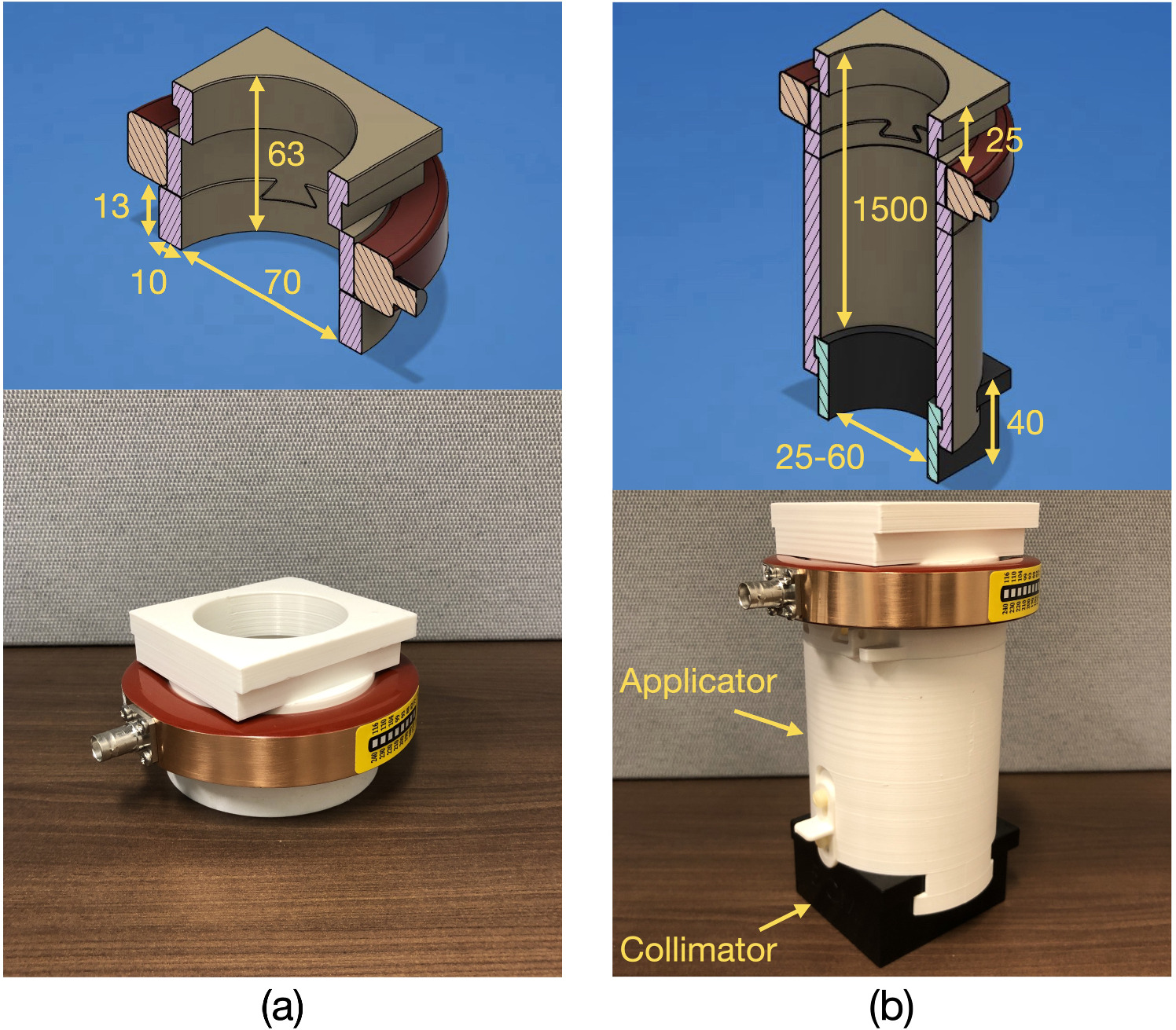
Figure 1. Custom 3D-printed applicators used in this work to accommodate the BCT: the (a) test applicator and (b) clinical applicator holding a Delrin collimator. Dimensions are in millimeters.
Download figure:
Standard image High-resolution image2.3.1. Effect of SSD
The effect of SSD on BCT signal was assessed by performing measurements with the BCT held by the test applicator at SSDs between 25 and 70 cm (BCT to surface distance of 6.5 cm to 51.5 cm), using slabs of Solid Water® (Gammex®, Middleton, WI) to define the surface. Measurements were done at 6 and 9 MeV.
2.3.2. Effect of field size
The effect of field size on BCT signal was evaluated by performing irradiations in air using the clinical applicator at 6 and 9 MeV, using Delrin collimators with apertures of 2.5 cm, 4 cm and 6 cm to shape the beam.
2.3.3. Effect of medium
The influence of the phantom material on the BCT response was assessed by comparing the signal captured when irradiating solid water and liquid water in a 68.0 cm × 40.7 cm × 35.0 cm water tank. Measurements were done at SSD ranging between 30 and 50 cm, using the test applicator to hold the BCT. Finally, BCT measurements were also acquired for the irradiation of a 5 cm solid water slab grounded through an aluminium foil and a conductive wire connected to a grounded Faraday cage protecting the electronics of the Linac, as shown in figure 2. Similarly, a solid water phantom with a plane-parallel Roos chamber (PTW, Freiburg, Germany) inserted at 1.6 cm depth was irradiated with the chamber both connected and unconnected to a powered Cardinal Health electrometer using biases of −300 V, 0 V and 300 V. BCT signal was recorded for all conditions, using an SSD of 25 cm and a beam of 9 MeV for both the irradiation of the grounded solid water and that of the solid water with a Roos chamber.
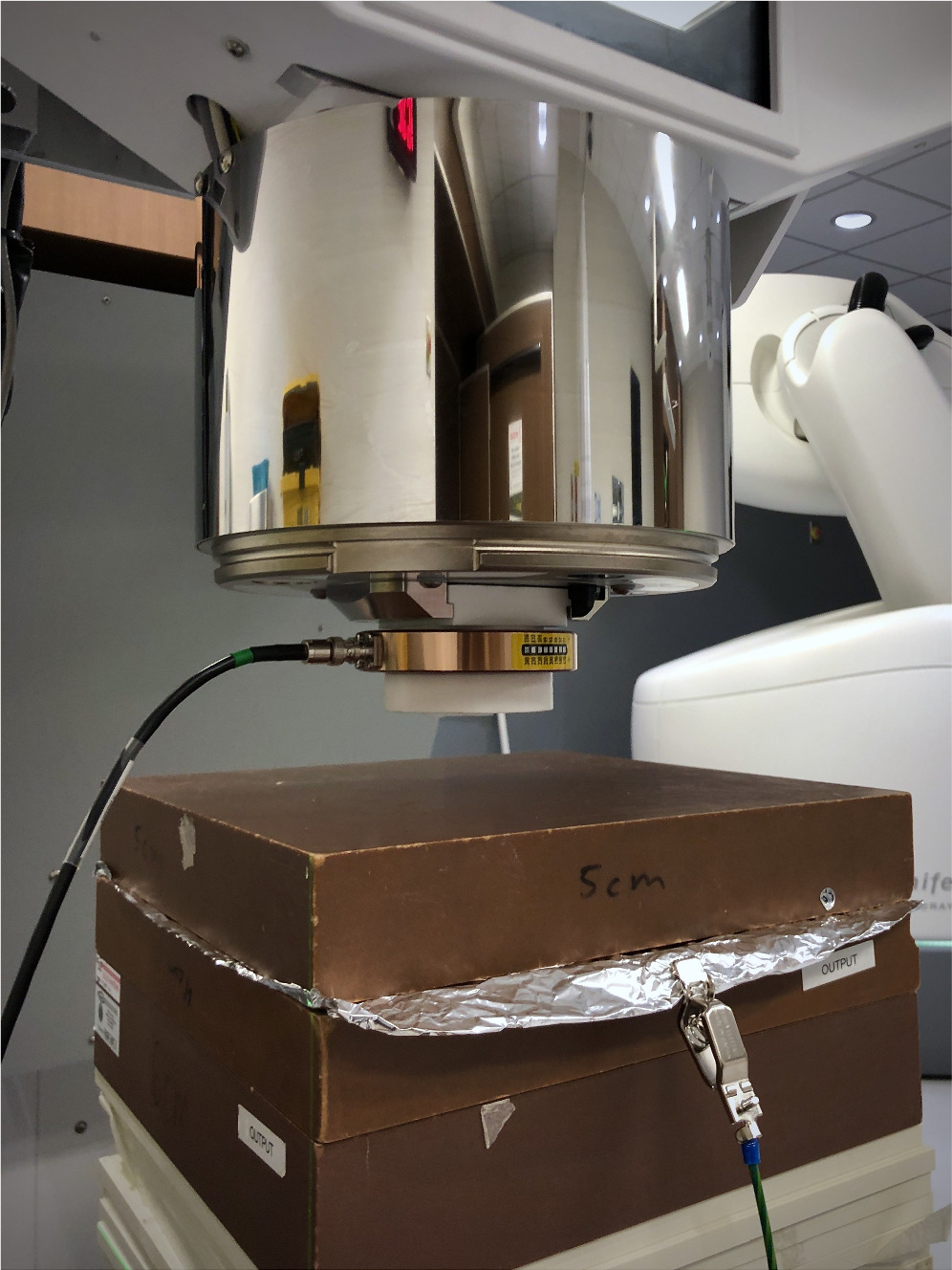
Figure 2. Setup used for the irradiation of a 5 cm solid water slab grounded with an aluminium foil connected to a conductive wire reaching a grounded Faraday cage on the linac.
Download figure:
Standard image High-resolution image2.3.4. Mitigation of signal perturbation with a faraday shield
The use of a Faraday shield was tested as a mitigation strategy for BCT sensitivity against setup and irradiation parameters. This was achieved by placing an aluminium foil directly at the exit of the test applicator, which was grounded to a Faraday cage on the linac head using a conductive wire with a clip at one end, as shown in figure 3(a). For the clinical applicator, the design was slighly adjusted to hold an aluminium foil at a distance of 1.3 cm below the BCT and above the collimator holder as shown in figure 3(b). All other characteristics of the applicator (material, length, diameter) were kept constant. Measurements for SSD, field size and material dependence were repeated to assess the impact of Faraday shielding on BCT signal variations. To achieve this, irradiations were duplicated with the aluminium foil installed on the applicators, either grounded or ungrounded. This was done to specifically assess the effect of Faraday shielding on the BCT signal, without interference from the presence or absence of the aluminum foil itself.
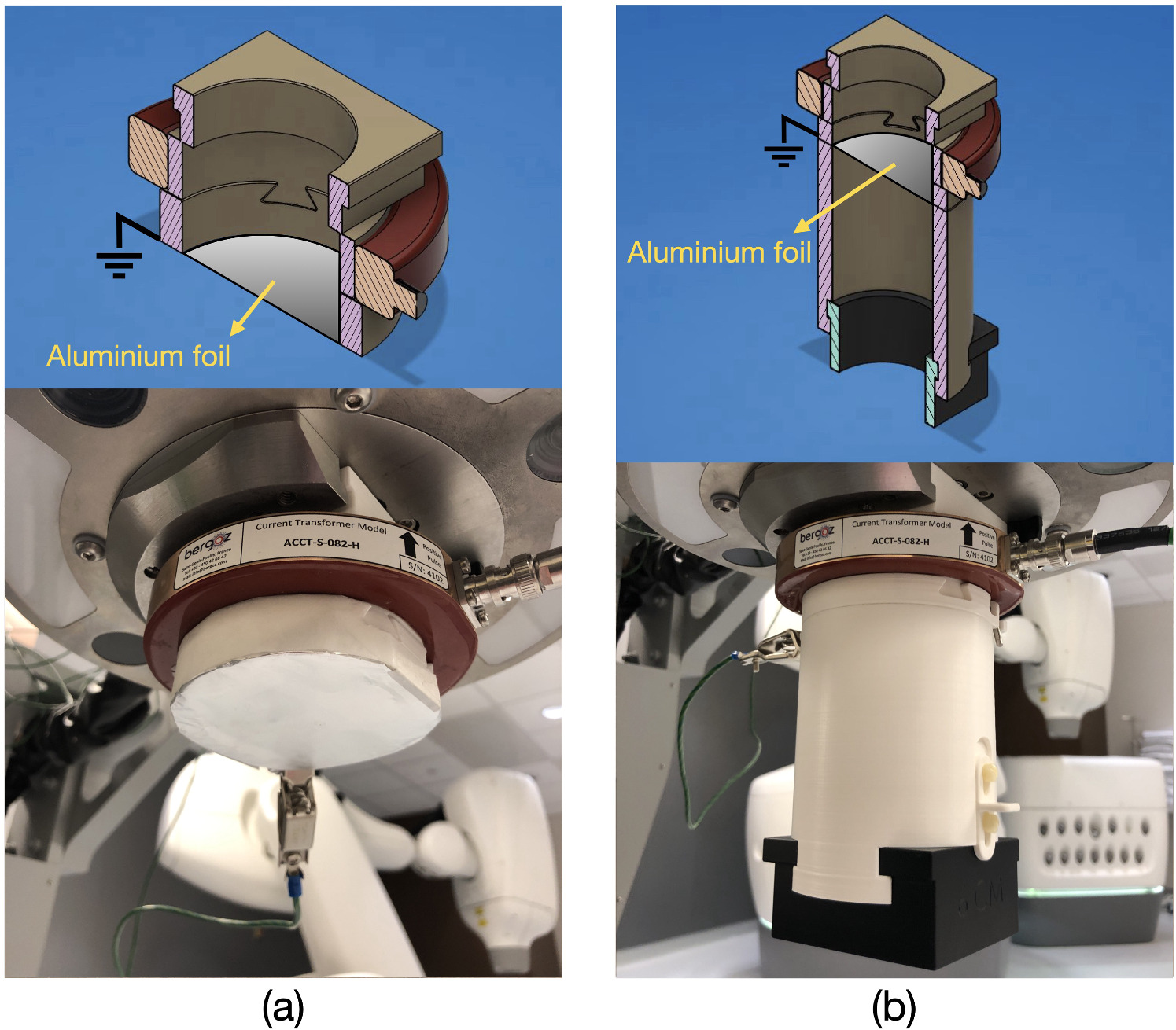
Figure 3. Integration of a Faraday shield in (a) the test applicator and (b) the clinical applicator.
Download figure:
Standard image High-resolution image3. Results
3.1. Monte Carlo simulations
Figure 4 (a) presents the backscattered fraction for monoenergetic electron beams directed towards a water phantom, as calculated by the backscatter_clrp EGSnrc user-code. As expected, low energy electrons yield a higher fraction of backscattered electrons, with a backscattered fraction around 5.5% for energies around 50 keV. For the nominal energies considered in this work (6 and 9 MeV), backscattered fractions on water are below 1%. Furthermore, the fraction of backscattered electrons for various materials at energies of 750 keV and 9 MeV is presented in figure 4 (b). Results indicate that water and Acetal, the material from which the Mobetron UHDR collimators are made, generate nearly identical fractions of backscattered electrons, around 1% at 9 MeV and less than 4% at 750 keV. For 9 MeV electrons, only lead induced a backscatter fraction above 10%.

Figure 4. Monte Carlo calculated fraction of incident electrons backscattered (a) on a water phantom as a function of energy and (b) on different materials for energies of 0.75 and 9 MeV.
Download figure:
Standard image High-resolution image3.2. Effect of SSD
Figure 5 shows the total signal captured by the BCT as a function of SSD for 6 and 9 MeV UHDR beams directed towards a solid water phantom. As observed in previous work (Liu et al 2023), the BCT signal is reduced at shorter SSD, despite constant beam output. The effect is slightly higher for the 6 MeV beam, with a variation of 26.5% between 25 and 70 cm SSD, compared to 12.6% at 9 MeV.
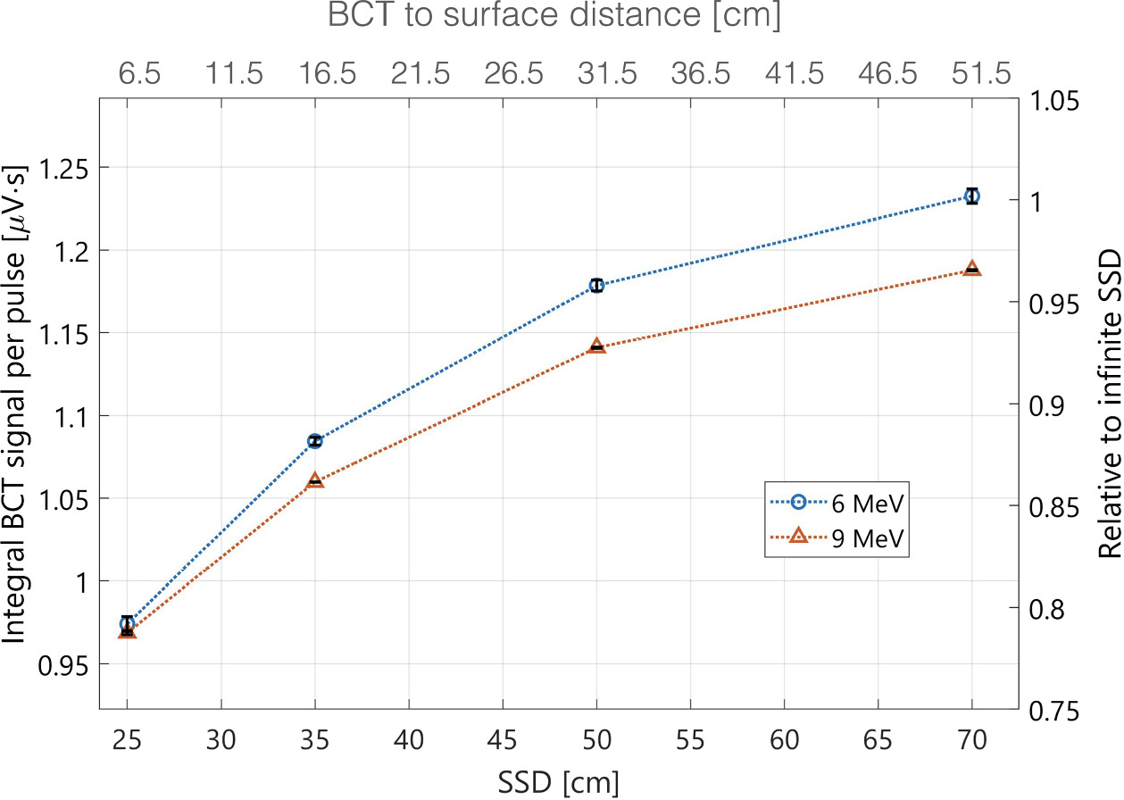
Figure 5. Mean integral BCT signal per pulse as a function of SSD for beam energies of 6 MeV and 9 MeV, using the test applicator. The black bars represent one standard deviation for the repeated measurements.
Download figure:
Standard image High-resolution image3.3. Effect of field size
The dependency of the BCT response as a function of the field size is presented in figure 6. The BCT signal is shown to increase with the collimator diameter, with variations as high as 15% between 2.5 cm and 6 cm field sizes for both energies. This behavior, opposite to the effect of jaw setting and collimation size for monitor ion chamber in conventional linac (i.e. lower signal for smaller field size), was also observed in previous work (Liu et al 2023).

Figure 6. Mean integral BCT signal relative to the 6 cm field size for beam energies of 6 and 9 MeV using the clinical applicator. The black bars represent one standard deviation for the repeated measurements.
Download figure:
Standard image High-resolution image3.4. Effect of medium
The effect of phantom material on BCT signal was explored by comparing the responses from solid water and water phantoms using a 9 MeV beam across four varied SSDs, ranging from 30 to 50 cm, as depicted in figure 7. Unexpectedly, we observed a substantial difference in the BCT readings between the two phantoms, with discrepancies as high as 14.1% for 30 cm SSD. More specifically, the readings observed when using the water phantom are shown to be relatively unaffected by changes in SSD, maintaining consistent pulse shape and amplitude for all distances. In contrast, the solid water phantom induced BCT signal with noticeable droop within each pulse, an effect shown to be reduced as the phantom was placed further and further from the BCT. Water and solid water are also shown to influence the BCT signal in different ways on a pulse-by-pulse basis, as reported in figure 8. First, one can see that all pulses yield a lower signal in solid water compared to water, but the difference between the two phantoms is shown to increase after the first pulse. Indeed, the signal quickly reduces after the first pulse when delivered to solid water, while the response is substantially more stable when delivered to water. Figure 9 provides more insights on how phantom properties might affect BCT signal. First, the plot in (a) shows that connecting our solid water phantom to the ground noticeably affected the pulse shape and the total signal measured, despite identical incident beams. Indeed, the grounded solid water results in a pulse shape that is flatter, akin to that seen in water, though not exactly to the same extent. This effect is also observed when a Roos chamber is either connected to or disconnected from the electrometer, with the connected chamber inducing a flatter pulse shape. These observations indicate that grounding a solid water phantom, whether directly or via an ion chamber, substantially impacts the BCT reading.
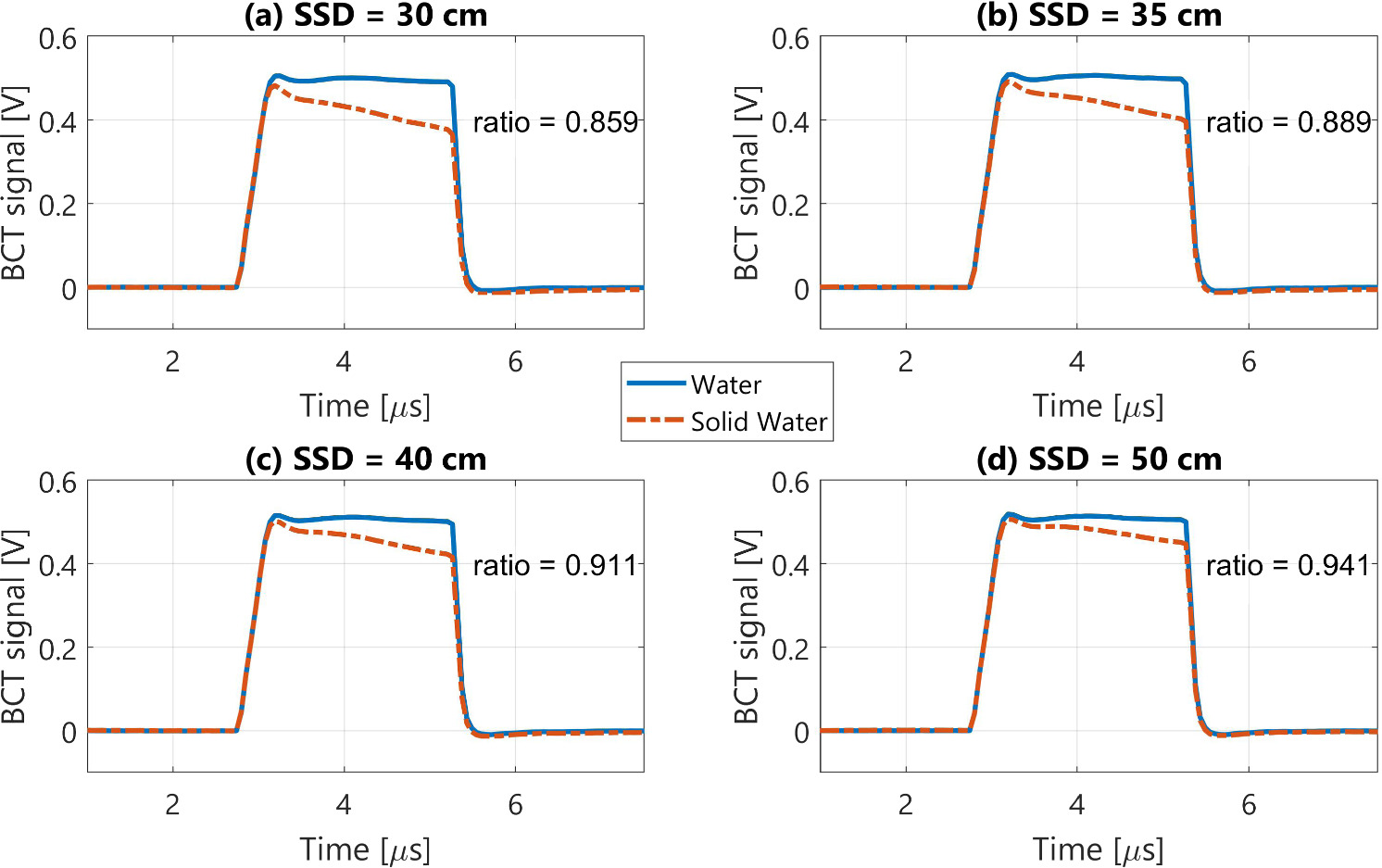
Figure 7. Mean BCT signal per pulse for various source-to-surface distance (SSD) for water and solid water phantoms using a 9 MeV UHDR beam. Each plot also reports the ratio of the mean integrated signal in solid water to the one in water.
Download figure:
Standard image High-resolution image
Figure 8. Mean BCT signal per pulse for the irradiation of (a) solid water and (b) water using a 9 MeV UHDR beam and a source-to-surface distance (SSD) of 30 cm. The integral BCT signal for scenarios (a) and (b) is presented in (c), where the black error bars show one standard deviation for the repeated measurements.
Download figure:
Standard image High-resolution image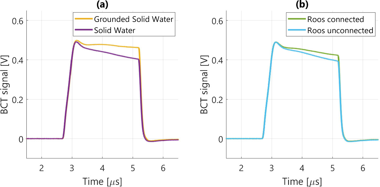
Figure 9. Mean BCT signal per pulse for the irradiation of (a) solid water grounded and ungrounded and (b) solid water with a Roos chamber either connected or unconnected to a powered electrometer using a 9 MeV UHDR beam. The bias applied to the chamber did not impact the BCT signal (not shown).
Download figure:
Standard image High-resolution image3.5. Mitigation with a Faraday shield
Figure 10 presents the signal measured by the BCT for a 9 MeV UHDR beam at various SSD using solid water, with the Faraday shield installed at the exit of the test applicator, either grounded or ungrounded. Results indicate that the Faraday shield removes essentially all SSD dependency when grounded, while the ungrounded shield generally reproduces what was reported in figure 5, where no aluminium foil was used.

Figure 10. Mean BCT signal per pulse for irradiations of a solid water phantom at various SSD using a Faraday shield (a) grounded and (b) ungrounded. The mean integral signal for scenarios (a) and (b) is presented in (c), where the black error bars show one standard deviation for the repeated measurements.
Download figure:
Standard image High-resolution imageSimilarly, figure 11 compares BCT signal for the same beam delivered to water and solid water phantoms at a SSD of 30 cm when a grounded Faraday shield is installed on the applicator. Here again, the phantom material-specific responses and inter-pulse variability observed respectively in figures 8 and 9 are cancelled, resulting in virtually identical BCT response for water and solid water when installing a grounded Faraday shield downstream of the BCT.
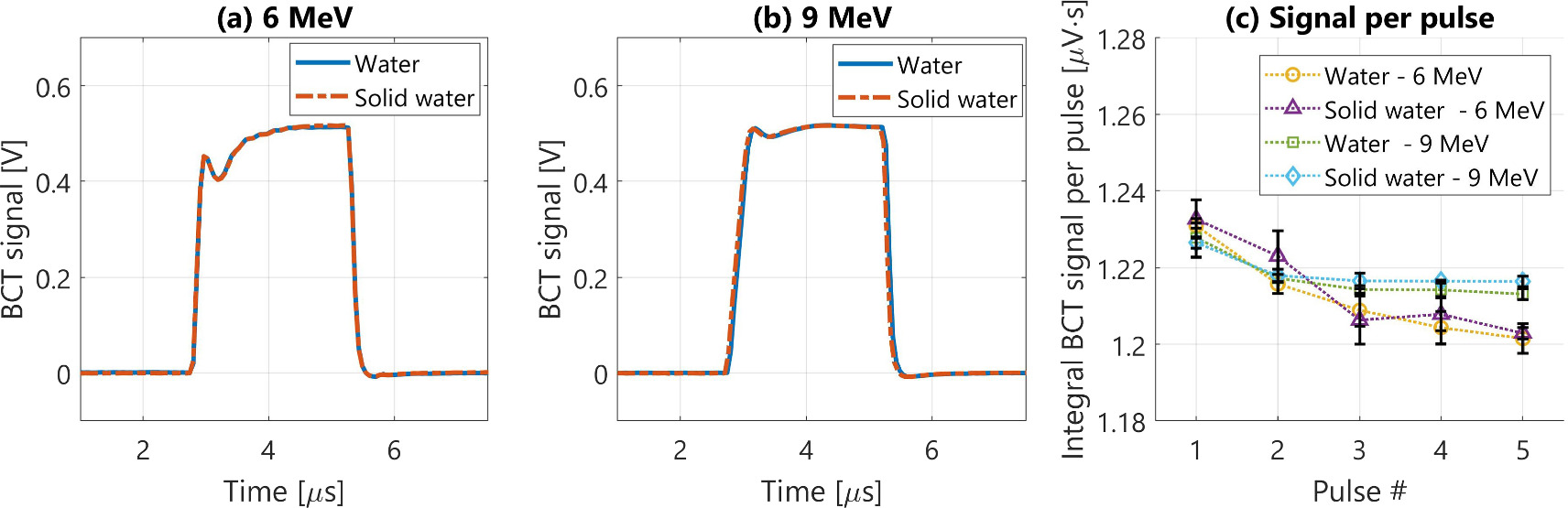
Figure 11. Mean BCT signal per pulse in water and solid water for three irradiations of five pulses each at (a) 6 MeV and (b) 9 MeV when using a grounded Faraday shield. The mean integral BCT signal per pulse for these irradiations is shown in (c), with the black error bars representing one standard deviation for the repeated measurements.
Download figure:
Standard image High-resolution imageFinally, figure 12 illustrates the impact of field size on the BCT signal when a grounded Faraday shield is incorporated into our clinical applicator. With the shield in place and grounded, the BCT signal variation across the three field sizes remains below 0.5% for a given energy. In contrast, when the aluminum foil is ungrounded, the field size influences the BCT signal in a manner consistent with the observations made in figure 6.
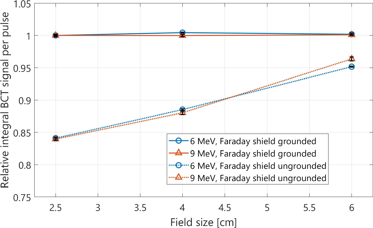
Figure 12. Mean integral BCT signal per pulse relative to the 6 cm field size with a grounded Faraday shield using the clinical applicator with a Faraday shield either grounded or ungrounded. The black error bars show one standard deviation for the repeated measurements.
Download figure:
Standard image High-resolution image4. Discussion
In this work, we investigated the effect of irradiation conditions on beam current transformer (BCT) signal, with the objective of enabling reliable electron UHDR real-time beam monitoring. While several groups have validated the linearity of BCT signal as a function of pulse length and pulse rate frequency for UHDR electron beam using a constant setup (Oesterle et al 2021, Goncalves Jorge et al 2022, Jain et al 2023), recent work has reported significant sensitivity of BCT signal (up to 12%) to changes in SSD, field size and phantom material despite constant beam parameters (Liu et al 2023). Until now, the main hypothesis to explain this behavior has been backscattered electrons modifying the net current detected by the device when travelling backwards in the toroid (Liu et al 2023). In this study, Monte Carlo simulations and experimental measurements were performed to test this hypothesis and provide a thorough understanding of the factors affecting BCT signal, while exploring solutions to ensure the robustness of BCT-based UHDR electron beam monitoring.
Monte Carlo simulations performed in this work indicate that the backscatter fraction from a mono-energetic electron beam in water is less than 5% for most relevant energies and less than 1% for energies above 4 MeV. This suggests that even if all backscattered electrons were detected by the BCT at short SSD and none were detected at large SSD, the difference in BCT signal between the two conditions should not be more than 2%–3% for 6 MeV and 9 MeV beams. While the Mobetron is known to have a low-energy component within its spectrum due to the absence of beam a steering magnet (Iaccarino et al 2011), no realistic spectrum could induce variations as high as the ones reported in previous work (Liu et al 2023) and reproduced in this study (more than 20% difference between 25 and 70 cm SSD for 6 MeV). Similarly, as shown in figure 4, the plastic used to make the Mobetron UHDR collimators, Acetal, induces less than 1% backscatter at 9 MeV, indicating that field size should only have a minor impact on BCT signal through backscattered electrons.
With the objective of identifying alternative causes for BCT signal variation as a function of SSD and field size, we compared signal obtained in solid water to that measured in water with otherwise identical beam parameters. Results obtained in these conditions, presented in figure 7, show a dramatic impact of the phantom type on the BCT response, even though water and solid water are considered equivalent in terms of MeV electron interaction properties (Tello et al 1995), including backscatter (Chow and Owrangi 2009). These results therefore suggest that a second phenomenon, unrelated to electron backscatter, substantially affected the BCT signal obtained using solid water.
Since one of the main differences between water and solid water is their electrical conductivity, we made the hypothesis that the effect could be related with the way charge dissipation occurs within the medium as the beam is delivered. Previous studies have demonstrated that some plastics (e.g. PMMA) could experience long-term charging following megavoltage electron irradiation at conventional dose rates (Rawlinson et al 1984, Thwaites 1984) and modern solid water phantoms have been optimized to circumvent this limitation (McEwen and Niven 2006). However, it is plausible that at very high beam current, solid water still experiences a transient charge loading phenomenon, where the electrons do not diffuse fast enough to reestablish charge equilibrium within the phantom. In that scenario, the build-up of negative charge in the irradiated region of the solid water phantom would induce a growing electric field, a phenomenon already observed and documented for strongly insulating plastics under megavoltage electron irradiation (Watson and Dow 1968).
To test if the difference between BCT signal captured for water and solid water phantoms was effectively due to the different levels of charge dissipation in each medium, we irradiated a 5 cm solid water slab placed above a thin aluminium foil grounded to earth through a conductive wire. Results, shown in figure 9, demonstrate that this indeed modified the BCT signal, even though all other irradiation parameters were kept constant. The shape of the pulse captured by the BCT for the grounded solid water was closer to the one measured in water, but not perfectly alike, suggesting partial but incomplete resolution of the charge build-up effect through the grounded foil.
From this point, to evaluate if charge dissipation in medium did affect BCT signal through an electric field generated by transient charge build up during irradiation, we added Faraday shields to prevent such an electric field from reaching the central region of the toroid. This was done on our two applicators by placing a thin aluminium foil just below the BCT on which a grounded electric wire could be connected. Then, measurements were performed at various SSD, field sizes and phantom materials with the foil grounded and ungrounded, to isolate the impact of the Faraday shielding from the simple addition of an aluminium foil downstream of the BCT. Results, reported in figures 10–12, unambiguously demonstrate that Faraday shielding was effective in removing virtually all SSD and field size dependence for the BCT measurements. Similarly, the shielded BCT yielded the same signal for solid water and water for otherwise constant irradiation parameters, as one should expect.
Considering our observations, it can be confidently asserted that the strong dependency of BCT signal as a function of SSD, field size and phantom material is most likely caused by an electric field originating in dielectric materials exposed to the UHDR electron beam. Indeed, for solid water irradiations, the intensity of the electric field through an unshielded BCT would decrease as the SSD increases, which reflects the effect observed in previous work (Liu et al 2023) and reproduced in this study. Similarly, transient charge loading of the collimator material would be more important for smaller field sizes (larger surface of Acetal being irradiated), which is again in line with what has been reported in this work. Although both effects could also be explained by electron backscatter in terms of relation with SSD and field size, our Monte Carlo simulations indicate that the amplitude of the observed effects on BCT signal is too large to be explained by backscatter alone. Instead, by removing virtually all SSD, field size and phantom material dependency through grounded Faraday shielding, our investigation provide strong evidence to support the hypothesis of an electric field originating in the irradiated material. To the best of our knowledge, this is the first time this effect has been identified and reported in the context of FLASH radiotherapy.
While an in-depth analysis of the processes through which the electric field impacted the BCT signal was beyond the scope of this work, we seek to demonstrate that this hypothesis is plausible and in-line with the various observations made in this work. The BCT signal, proportional to the magnetic field B within the toroid, is governed by the Ampère–Maxwell equation:

where
J
is the current density in the aperture of the BCT and
E
is the electric field within the aperture of the BCT. Based on this equation, the effect of an electric field on the BCT signal can either come directly from its variation in time  , or through its influence on the total current density within the BCT,
J
. Our observations suggest that both effects can be present, as schematically represented in figure 13. For the
, or through its influence on the total current density within the BCT,
J
. Our observations suggest that both effects can be present, as schematically represented in figure 13. For the  term, calculations provided in the appendix A show that the growth of the electric field during irradiation could reduce the BCT signal by up to 10% at short SSD. At a few tens of centimeters between the BCT and the charged surface, our calculation however indicates that the rising electric field should only have a negligible impact on the BCT signal. Since we observed signal perturbations at BCT to surface distances up to 50 cm, it is likely that the electric field also impacts the BCT signal through the current density
J
. For this contribution, we make the hypothesis that when the electric field within the beam's path reaches a sufficiently high amplitude, the immediate recombination of ion pairs generated in air becomes hindered. This, in turn, would lead to the initiation of a drifting current that opposes the direction of the beam, similar to an ion chamber operated in the recombination region. This would explain why the signal perturbation increases with pulse width, as additional charges would induce a larger field strength which would in turn increase the magnitude of this opposing current. While the estimation of the current associated with the incomplete recombination of charges released in air in the presence of an electric field is complex, calculations provided in appendix A show that the total charge of a single 2.4 μs pulse from the Mobetron is enough to induce an electric field up to 50 kV m−1 at 5 cm from the phantom's surface and up to 5 kV m−1 at 25 cm. Considering that a Farmer chamber operated at 150 V induces an internal electric field of approximately 50 kV m−1, it is likely that a non-negligible amount of the charges generated in air by the primary beam within the toroid do not recombine instantly, are drifted in the electric field and induce a magnetic field opposing the one from the primary beam. Additional experiments supporting the presence of at least two different mechanisms affecting the BCT signal are presented in appendix B.
term, calculations provided in the appendix A show that the growth of the electric field during irradiation could reduce the BCT signal by up to 10% at short SSD. At a few tens of centimeters between the BCT and the charged surface, our calculation however indicates that the rising electric field should only have a negligible impact on the BCT signal. Since we observed signal perturbations at BCT to surface distances up to 50 cm, it is likely that the electric field also impacts the BCT signal through the current density
J
. For this contribution, we make the hypothesis that when the electric field within the beam's path reaches a sufficiently high amplitude, the immediate recombination of ion pairs generated in air becomes hindered. This, in turn, would lead to the initiation of a drifting current that opposes the direction of the beam, similar to an ion chamber operated in the recombination region. This would explain why the signal perturbation increases with pulse width, as additional charges would induce a larger field strength which would in turn increase the magnitude of this opposing current. While the estimation of the current associated with the incomplete recombination of charges released in air in the presence of an electric field is complex, calculations provided in appendix A show that the total charge of a single 2.4 μs pulse from the Mobetron is enough to induce an electric field up to 50 kV m−1 at 5 cm from the phantom's surface and up to 5 kV m−1 at 25 cm. Considering that a Farmer chamber operated at 150 V induces an internal electric field of approximately 50 kV m−1, it is likely that a non-negligible amount of the charges generated in air by the primary beam within the toroid do not recombine instantly, are drifted in the electric field and induce a magnetic field opposing the one from the primary beam. Additional experiments supporting the presence of at least two different mechanisms affecting the BCT signal are presented in appendix B.

Figure 13. Suggested mechanisms to explain the effect of the electric field on the BCT signal.
Download figure:
Standard image High-resolution imageObservations reported in this work have important implications for the use of BCT to monitor UHDR electron beams. First, our study showed that robust BCT calibration is probably not achievable if the effect of transient charge loading in media is not accounted for. Indeed, the BCT response presented in figure 7 shows that a dramatically different signal can be obtained for the same irradiation delivered to water and solid water. Therefore, a BCT calibrated against a reference detector in solid water is likely to report an inaccurate beam output if the beam is then used to irradiate a subject of different electrical conductivity (e.g. irradiation of cell cultures, organoids, a small animal or a human subject) if this effect is overlooked, as the electric field generated during calibration and beam monitoring might be drastically different. Similarly, using a BCT to correct beam output fluctuations for the cross calibration of an ion chamber and a passive detector (e.g. radiochromic film, alanine, etc.) in solid water should be discouraged if a Faraday shield is not used, as our results indicate that the presence of a connected ion chamber can reduce the BCT signal perturbation caused by solid water. Finally, for BCTs with a wide enough dynamic range to cover conventional and UHDR irradiations (Lahaye et al 2022, Vojnovic et al 2023), outcome comparisons between the two regimes based on the BCT signal would likely be biased if the effect of electric fields is not taken into account.
Based on our observations, strategies to prevent electric fields from affecting the BCT signal are warranted to enable the translation of BCT-based electron UHDR beam monitoring. Although different designs might yield BCT variations of a lower amplitude than what was reported in this work (e.g. with the BCT incorporated to the linac head, further from the collimator and phantom's surface), our general conclusions are expected to remain relevant in these setups, provided that a conductive and grounded window serving a different purpose is not already placed downstream of the BCT. According to the drawings shown in Liu et al (2023) and Di Martino et al (2023), at least two UHDR electron linac models are offered with integrated BCTs placed downstream of any grounded conductive window. While effective, the aluminium foil used in this work was primarily selected for its accessibility and simplicity of integration and might not be the optimal approach in a beam monitoring setting. Since the whole inner-aperture of the toroid needs to be covered by the shield, interactions with the electron beam appears to be inevitable. For this reason, different designs might be more appropriate to limit the effect of the shield on the electron beam's dosimetric properties. Optimization of the position, thickness and composition of the Faraday shield was beyond the scope of this work but warrants future investigation.
5. Conclusion
In conclusion, this study has explored the relationship between beam current transformer (BCT) signal variations and irradiation parameters in ultra-high dose rate (UHDR) electron beam monitoring, challenging previous assumptions and introducing new perspectives. Our investigations, combining Monte Carlo simulations and experimental measurements, have demonstrated that the impact of backscattered electrons on BCT signal is less significant than previously thought. Instead, our results unveiled the substantial influence of the electric field generated by the transient charging of plastic materials under UHDR electron irradiation. The introduction of Faraday shielding was shown to be a promising solution to mitigate the discrepancies in BCT signal across varying conditions and phantom materials. Future research should delve deeper into optimizing Faraday shielding materials and configurations, ensuring the robustness and consistency of BCT signal in clinical scenarios.
Acknowledgments
The authors acknowledge the contribution of Mathieu D'amours for the production of the custom applicators and Étienne Delisle for the Matlab script.
Data availability statement
The data cannot be made publicly available upon publication because they are not available in a format that is sufficiently accessible or reusable by other researchers. The data that support the findings of this study are available upon reasonable request from the authors.
Appendix A
This appendix estimates the potential influence on the BCT signal of an electric field emanating from a phantom undergoing charge deposition. As stated in the discussion, the BCT signal is proportional to the magnetic field B within the toroid, which is defined by the Maxwell–Ampère equation:

where J is the current density in the aperture of the BCT, E is the electric field within the aperture of the BCT and μ is the permeability of the toroid. In its integral form, equation (A1) becomes:

where Σ is any surface with a closed boundary ∂Σ. In our case, Σ is the internal surface of the BCT, while ∂Σ is the closed boundary of the BCT aperture. First, let us assume that only the primary beam contributes to J (no secondary charges creating an opposing current). In this case, equation (A2) becomes

where Ibeam
is the primary beam's current defined by the number of charges per unit of time. To estimate the influence of a variable electric field on the BCT signal, let us approximate all charges from the primary beam are accumulated in a uniformly charged sphere, centered at depth d below the surface. While this approximation is chosen to simplify the calculations, similar results are expected for most realistic deposition patterns at larger distances. In that scenario, the electric field along the radial axis of the sphere  as a function of time is given by:

where z is the distance between the surface and the BCT and Q(t) is the charge of the sphere at time t. For the sake of simplicity, let us approximate that the electric field is constant and perpendicular to the aperture of our BCT of radius R . In these conditions, the integral of the electric field over Σ becomes simply:

Combining equations (A4) and (A5) gives:

Neglecting charge dissipation during the irradiation,  which then gives:

Finally, incorporating (A7) into (A3) yields:

Let α be the ratio of the contribution of the variable electric field and the primary beam on B . Considering the simplifications made in this analysis (negligible instantaneous charge dissipation, uniform and perpendicular field lines within the BCT), α represents the upper limit (worst-case scenario) of the BCT perturbation that could be induced by the varying electric field alone. Based on this definition and equation (A8):


Using R = 4.1 (the inner radius of our BCT) cm and d = 3 cm (the average R50 for 6 and 9 MeV electrons), figure A1 shows the value of α as a function of the distance between the BCT and the phantom's surface. As pointed out in the discussion, this calculation suggests that the variable electric field can represent around 10 % of the primary beam's impact on the BCT signal at short BCT to surface distance, while becoming negligible beyond 30 cm.

Figure A1. Ratio between the magnetic field induced by the primary beam current and the charge accumulating in a sphere centered 3 cm below the surface as a function of the distance from the surface [cm].
Download figure:
Standard image High-resolution imageThe second term that can influence the magnetic field B is the net current density J travelling within the toroid. Equation (A4) can also be used to estimate the electric field amplitude as a function of the charge stored in the sphere considered in this example. According to the vendor, the sensitivity of our BCT and readout system is 33.33 V/A. Based on this and the signal measured by the shielded BCT in figures 10 and 12 (≈1.23 μV·/pulse) the total charge for a single pulse in the setting used in this work is around 37 nC for our 9 MeV beam. Assuming that all electrons remain temporarily stored within the charged sphere considered above, equation (A4) estimates the electric field strength as a function of surface distance as shown in figure A2.

Figure A2. Static electric field as a function of distance on the radial axis sphere uniformly charged by 37 nC and centered at 3 cm below the surface.
Download figure:
Standard image High-resolution imageAs mentioned in the discussion, our results suggest that the electric field strength induced by a single pulse can reach up to 50 kV m−1 at 5 cm from the surface while remaining around 5 kV m−1 at a distance of 25 cm. In reality, the field must be lower at the beginning of the first pulse and might be larger for subsequent pulses, depending on the charge dissipation rate and pulse frequency. The fact that the BCT signal perturbation was shown to be larger after the first pulse supports this hypothesis while suggesting some level of inter-pulse charge accumulation can happen in the solid water phantom.
Appendix B
In this appendix, we provide additional measurements supporting the hypothesis that at least two different mechanisms drive the influence of the electric field on the BCT signal.
When all electrons are stopped in the middle plane of a solid water phantom, the electric field should be relatively symmetric above and below the phantom. Based on this assumption, if only the variable electric field  affects the BCT signal, the same perturbation should be obtained at equal distances of above and below the phantom. In this context, signal perturbation would mean the difference between the BCT signal measured in a given setup and the one expected from the primary beam in those conditions. When the BCT is placed above the solid water phantom, this simply means the difference in signal with an without a solid water phantom. For the setup with the BCT placed below the solid water phantom, this means the absolute signal measured, as no primary beam is present in these conditions and only the variable electric field could influence the BCT.
To test this hypothesis, we irradiated an 8 cm thick water phantom with a 9 MeV beam at a SSD of 25 cm, using the same irradiation parameters as used in this work (5 pulses of 2.4 μs). This thickness was chosen so that most of the charges were stopped close to the middle plane of the phantom, around R50 (Vandyk & MacDonald 1972). We then placed our BCT below the solid water phantom at distances from the lower surface of the phantom ranging between 5.5 and 20.5 cm by progressively removing slabs of Styrofoam below the BCT, as shown figure B1 (a). The BCT orientation with respect to the beam was kept the same as for the setup above the water phantom, to make sure that the electric field would generate a positive pulse signal detectable by our pulse detection algorithm. Figure B1 (b) shows that we indeed measured a signal in the BCT when it is placed below the water phantom, despite the fact that its thickness was twice the range of the incoming electrons. It is also interesting to observe that in these conditions, the signal was stable across all pulses, suggesting that  is relatively constant from one pulse to another. This contrasts with the effect observed with the BCT above the phantom, where the perturbation is shown to increase after the first pulse.

Figure B1. (a) Setup used to measure the BCT signal as a function of the distance below the solid water phantom. (b) BCT signal per pulse measured at a BCT to surface distance of 5.5 cm below the 8 cm thick solid water phantom for an electron beam of 9 MeV.
Download figure:
Standard image High-resolution imageIn figure B2, the signal measured below the water phantom is reported as a function of the distance between the BCT and the surface below the phantom. In the same plot, we report the missing signal for the setup with the BCT above, i.e. the total BCT signal obtained with a grounded Faraday shield minus the one obtained without a shield for different BCT to surface distances. Results indicate that the amplitude of the perturbation is systematically higher when the BCT is placed above the phantom compared to what is obtained when the BCT is placed below for the same BCT to surface distance.

Figure B2. Mean BCT signal perturbation per pulse as a function of BCT to surface distance for the BCT placed above and under an 8 cm thick solid water phantom using a 9 MeV UHDR electron beam. For the BCT position above the phantom, the signal perturbation represents the signal obtained using a Faraday shield minus the one obtained without a Faraday shield for a given distance. For the BCT placed below the water phantom, the signal perturbation is the integral signal measured per pulse.
Download figure:
Standard image High-resolution image
Assuming that the growing electric field has a similar amplitude above and below the phantom for the same BCT to surface distance, our results support the hypothesis that at least one other mechanism drives the influence of the electric field on the BCT signal when it is placed above the phantom, around the primary beam. Even in the case where the charge deposition was biased towards one side of the phantom, our general conclusions would hold as a distance shift of more than 20 cm is required to observe the same signal perturbation above and below the phantom. Finally, despite the observations provided in this appendix that support our hypothesis, it is important to note that the formal validation of the proposed mechanisms would only be achieved by a substantially more advanced set of experiments, which are beyond the scope of this study.