
Abstract
In magnetic resonance (MR) guided radiotherapy, the magnetic field-dependent change in the dose response of ionization chambers is typically included by means of a correction factor  . This factor can be determined experimentally or calculated by means of Monte Carlo (MC) simulations. To date, a small number of experimental values for
  at magnetic flux densities above 1.2 T have been available to benchmark these simulations. Furthermore, MC simulations of the dose response of ionization chambers in magnetic fields (where such simulations are based on manufacturer blueprints) have been shown to converge with results that deviate considerably from experimental values for orientations where the magnetic field is perpendicular to the axis of the ionization chamber and the influence of the magnetic field is largest.
In this work,  was simulated for a PTW 30013 Farmer ionization chamber using an approach based on finite element simulations. First, the electrical field inside the ionization chamber was simulated using finite element methods. The collecting volume of the ionization was not defined in terms of the physical dimensions of the detector but in terms of the simulated electrical field lines inside the chamber. Then, an MC simulation of the dose response of a Farmer type chamber (PTW 30013) was performed using EGSnrc with a dedicated package to consider the effect of the magnetic field. In the second part,
  was determined experimentally for two different PTW 30013 ionization chambers for a range of magnetic flux densities between B = 0 and 1.5 T, covering the range of commercially available MR-linacs.
In the perpendicular orientation, the maximum difference between the simulated values for  and the experimental values for
  was 0.31(30)% and the minimum difference was 0.02(24)%. For the PTW 30013 ionization chambers, the experimental values for
  were 0.9679(1) and 0.9681(1) for a magnetic flux density of 1.5 T. The value resulting from the simulation was 0.967(3).
The comparison of the correction factors simulated using this new approach with the experimental values determined in this study shows excellent agreement for all magnetic flux densities up to 1.5 T. Integrating the explicit simulation of the collection volume inside the ionization chambers into the MC simulation model significantly improves simulations of the chamber response in magnetic fields. The results presented suggest that intra-type variations for  may be neglectable for ionization chambers of the PTW 30013 type.
Export citation and abstract BibTeX RIS

Original content from this work may be used under the terms of the Creative Commons Attribution 3.0 licence. Any further distribution of this work must maintain attribution to the author(s) and the title of the work, journal citation and DOI.
Introduction
Recently developed commercial MR-linac devices (Raaymakers et al 2009, Mutic and Dempsey 2014) are now available for research purposes and for patient treatment at many institutions. Protocols for reference dosimetry have been developed for these devices since their introduction. The key point about dosimetry in MR-linacs is the change of response of the ionization chambers due to the influence of the magnetic field (Meijsing et al 2009) existing permanently in MR-linacs with magnetic flux density up to 1.5 T. Therefore, the change in the response caused by the magnetic field must be corrected; several formalisms have been proposed for this purpose (O'Brien et al 2016, van Asselen et al 2018). Several publications have addressed this problem for a wide range of detectors using Monte Carlo (MC) simulations (Meijsing et al 2009, Malkov and Rogers 2016, O'Brien et al 2016, Spindeldreier et al 2017). However, significant differences were found between calculated and measured detector responses in magnetic fields, especially for magnetic flux densities above 1 T. Van Asselen et al (2018) reviewed simulation results and compared it to experimental values; for a standard Farmer type chamber in specific orientations a discrepancy of more than 1% was found.
Malkov and Rogers (2017) and Spindeldreier et al (2017) have hypothesized that the discrepancy between the experimental results and the MC results can be explained as being due to regions of reduced local response near the guard ring of the detector; this is not considered in conventional MC simulations. This leads back to the question of whether the collecting volume of an ionization chamber (i.e. the volume from which ions are collected) coincides with the sensitive volume defined by the chamber geometry. Ross (2009) describes an approach wherein the collecting volume is different from the geometrically defined sensitive volume due to inhomogeneities in the electric field inside the ionization chamber. Ross suggests that the collecting volume can be calculated by running finite element (FEM) simulations of the electric field inside the ionization chamber and reducing the sensitive volume by the volume where the electric field lines that emerge from the ionization chamber's wall reach the guard ring instead of the electrode. This approach was recently implemented by Looe et al (2018) and led to an agreement between the measurements and the simulations of about 0.5% for a small volume ionization chamber that was positioned parallel to the radiation beam and perpendicular to the magnetic field up to 1.4 T. However, it has been shown that, for this orientation, the influence of the magnetic field is small (Looe et al 2018); in addition, the magnetic flux density inside current MR-linacs surpasses 1.4 T (Raaymakers et al 2009).
This work aims to improve the current situation by presenting new experimental results for a conventional ionization chamber up to a magnetic flux density of 1.5 T; these results are based on measurements in a well-defined experimental setup. The usage of FEM-based adjustments of MC detector simulations in magnetic fields is tested in the orientation where the ionization chamber is perpendicular to both the magnetic field and the beam direction and therefore the electron trajectories are deflected towards the stem or tip of the ionization chamber by means of the Lorentz force (figure 1). This orientation has been shown to be problematic in previous publications (Malkov and Rogers 2017, Spindeldreier et al 2017, van Asselen et al 2018) and differs from that tested in the previous publication by Looe et al (2018).
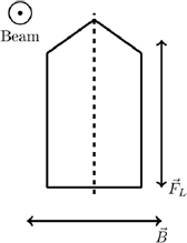
Figure 1. Possible directions of the Lorentz force ( ) for a setup where the magnetic field (
 ) is perpendicular to the axis of the ionization chamber. In this work, negative magnetic flux densities correspond to the situation wherein the secondary electrons are deflected to the tip of the ionization chamber, while positive magnetic flux densities correspond to the situation wherein the electrons are deflected to the stem of the ionization chamber.
Download figure:
Standard image High-resolution imageFor the MC detector simulation, we utilized the EGSnrc software package. EGSnrc includes dedicated usercodes for the simulation of the response of ionization chambers and was optimized for this purpose for many years (Rogers 2006).
It has been found previously that the correction to the response of the chamber is substantially larger when the chamber axis is oriented perpendicular to the magnetic field compared to the case of a parallel orientation (van Asselen et al 2018). A parallel orientation is therefore beneficial for clinical practice and often preferred. Nevertheless, it is important to find the reason for the discrepancy between Monte Carlo calculations and experiments in perpendicular orientation, to guarantee reliable Monte Carlo results for ionization chamber simulations in magnetic fields in general.
Material and methods
Formalism
In this paper, we follow the notation of van Asselen et al (2018). In the formalism below, the magnetic field correction factor  is defined as:

Here,  represents the ratio of absorbed doses to water at the point of measurement with and without a magnetic field and
  is the ratio of detector responses without and with a magnetic flux density
  .
.
All experimental and simulated results are presented as  , since this is the most direct way to compare simulations and experiments.
Orientation
For simulations and experiments in this work, the Farmer type ionization chambers were set up in such a way that all pairwise orientations between the magnetic field vector, the ionization chamber axis and the beam direction were perpendicular. The secondary electrons are deflected by the Lorentz Force ( ) either to the ionization chamber's tip or its stem (figure 1).
In the following, all negative magnetic flux densities correspond to a situation in which the electrons are deflected to the tip of the ionization chamber; for a positive sign of the magnetic flux density, the electrons are deflected towards the stem of the ionization chamber.
Experiments
All experiments were carried out using the Metrological Electron Accelerator Facility (MELAF) (Schüller et al 2019) at PTB, the national metrology institute of Germany, in Braunschweig. A large electromagnet (Bruker ER073W) with a 6 cm gap between its pole shoes was placed in front of an Elekta Precise accelerator (151605). A 6 × 20 × 20 cm3 water phantom (constructed by PTB) was positioned between the pole shoes of the magnet at a source-to-surface distance (SSD) of 110 cm. Ionization chambers were mounted within this phantom at a well-defined reference point and irradiated by a horizontal photon beam with a nominal accelerating voltage of 6 mV, which was collimated to 4 × 10 cm2 at the isocenter (source to axis distance 100 cm) to avoid backscattering effects from the pole shoes. Each measurement was repeated three times for each detector (S/N 006762 and 009193) on different days, including a full repositioning in the water phantom. A chamber voltage of 250 V was applied to the Farmer ionization chambers.
For the measurement of the relative response under different magnetic flux densities, a transmission monitor chamber was mounted onto the shadow tray of the accelerator head (Kapsch and Krauss 2009). The distance between the source and the transmission monitor chamber was 67.5 cm. Measurements had shown that the magnetic flux density of the magnetic fringe field at the position of the transmission monitor chamber does not surpass 1 mT and is therefore assumed to have a neglectable influence on the response of the transmission monitor chamber. This was checked by positioning an ionization chamber 3 m behind the electromagnet and comparing the signal of this ionization chamber (which is unaffected by the fringe field) with the signal of the transmission monitor chamber both with and without the magnetic field. No significant influence of the fringe field on the response of the monitor chamber was found in this measurement.
Ionization chambers under test were preirradiated with at least 1000 MU before the start of each measurement, while the stability of the ratio of the chamber signal to the monitor chamber was monitored online to avoid any settling effects (Ken Shortt et al 2005). After this, the beam was maintained in an active state, and the electrical charges collected over a 150 s period by the monitor chamber and the ionization chamber under test were measured simultaneously using Keithley 6517 (Keithley Instruments, Solon, USA) electrometers. Then, the magnetic flux density was altered remotely from the control room while the beam was maintained in an active state. This included an adjustment of the accelerator's steering magnets to compensate for the small deflection of the electron beam inside the accelerator due to the magnetic fringe field. The magnetic flux density was measured throughout the entire experiment by a hall sensor placed between the electromagnet pole shoes (DTM 151 Digital Teslameter, Group 3 Technology, Auckland, New Zealand). The measurements were repeated in steps of 0.15 T for both possible magnetic field directions and for an additional point at 0.35 T, which corresponds to the magnetic flux density of the ViewRay MRIdian MR-linac (ViewRay Technologies, Cleveland, USA). Later, the relative response was calculated as the ratio of the charges collected by the detector to the charge collected by the monitor chamber, normalized to the corresponding ratio at 0 T. Given uncertainties include only the Type A uncertainty component (JCGM 2008).
Simulations
For the simulation of the electric field inside a PTW 30013 ionization chamber, COMSOL Multiphysics version 5.3, a finite element simulation program, was used. The ionization chamber was modeled in COMSOL according to the manufacturer's engineering drawings; Maxwell equations were solved for a ground potential on the guard ring and the electrode and for 250 V on the graphited wall of the ionization chamber (figure 2). A script was written to extract the last field line leading from the chamber wall to the guard instead of to the central electrode, and to calculate a dead volume of no response based on this line. This volume was used in combination with the EGSnrc Monte Carlo framework (Kawrakow et al 2013). A detailed model of the ionization chamber was created for EGSnrc, including the dead volume calculated beforehand by means of finite element simulations (figure 2). The cross sections and physics parameters in EGSnrc were chosen in accordance with ICRU90 (ICRU 2014) and earlier simulation studies (Pojtinger et al 2018). This was achieved by utilizing the Mcdf-xcom photon cross sections and enabling atomic relaxation. The energy cut-off was set to 0.521 MeV for electrons and 0.01 MeV for photons. For the simulation of the external magnetic field, the most recent magnetic field macro (Malkov and Rogers 2016) was used. The egs_chamber usercode (Wulff et al 2008) was utilized for all simulations. This usercode was developed especially for ion chamber simulations and provides advanced variance reduction methods as intermediate phase space-storage and photon cross section enhancement (XCSE). XCSE was activated as suggested in Wulff et al (2008). To this end, a 1 cm cylindric water shell was modeled around the ionization chamber; for each medium inside the shell cross section enhancement was activated with an enhancement factor of 64. For simulation of the photon beam, a full accelerator head model was created in BEAMnrc and coupled to the egs_chamber usercode. The uncertainty given below for simulation results is the variance of the Monte Carlo simulation using a coverage factor of k = 2 to approximate an 95% coverage interval (JCGM 2008).
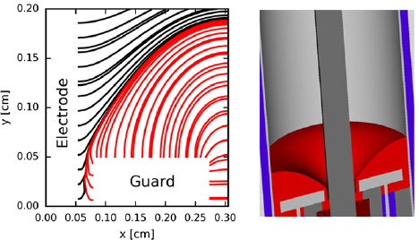
Figure 2. Calculated electric field lines (left) and adjusted Monte Carlo model (right). The region excluded from the sensitive volume is shown in red. The x coordinates correspond to the sagittal distance to the chamber axis and the y coordinates represent the longitudinal distance from the base of the guard ring.
Download figure:
Standard image High-resolution imageResults
The experimental results can be found in figure 3 and table 1. The experimental standard deviation  was calculated based on the three measurements taken for each detector. The maximum experimental standard deviation over all magnetic flux densities
  is shown in table 1.
Table 1. Experimental values for  .
.
 |
 [%] [%] |
||||
|---|---|---|---|---|---|
 |
 |
 |
 |
||
| PTW 30013—006762 | 0.9679(1) | 0.9695(1) | 0.9769(1) | 0.9647(1) | 0.11 |
| PTW 30013—009193 | 0.9681(1) | 0.9695(1) | 0.9771(1) | 0.9647(1) | 0.16 |
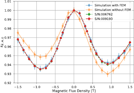
Figure 3. Comparison of the experimental values of  , for a PTW 30013 Farmer ionization chamber and the FEM-adjusted Monte Carlo simulation. For comparison, the figure also includes the results of a simulation without the FEM adjustments.
Download figure:
Standard image High-resolution image
The PTW 30013 Farmer chamber showed an increased response when the electrons were deflected to the tip (B < 0 T) as well as when the electrons were deflected to the stem (B > 0 T) of the ionization chamber; however, when the magnetic flux density was increased to more than 1 T, the response decreased. When the experimental results for the two different chambers were compared, the results for the relative response in magnetic fields matched within 0.04%. The small differences also highlight the excellent reproducibility of the experimental method.
The FEM calculations resulted in a dead volume of 0.04 cm3, which equals 7% of the nominal sensitive volume. Figure 3 shows the experimental results obtained for the PTW 30013 ionization chamber compared to the results of the FEM-adjusted MC simulation, as well as the result of a simulation without FEM adjustments in which the sensitive volume coincides with the physical dimensions of the chamber cavity. To compare the results, the mean of the squared deviations between the values of  resulting from the experimental measurements and the simulations was calculated. For the FEM-adjusted simulation, the mean squared deviation is 0.21(34)%, while a value of 1.03(32)% was found for the simulation without FEM adjustments. The maximum difference between the simulation and the experiment is 0.31(30)% at B = 1.5 T and the minimum difference is 0.02(24)% at B = −0.45 T.
Discussion
The introduction of FEM adjustments to the Monte Carlo simulations has significantly improved the consistency of the calculated values with the experimental results. For Farmer type ionization chambers in perpendicular orientations, the deviation between the simulated and experimentally obtained dose responses in magnetic fields was reduced to less than 0.31(30)% for all values of the magnetic flux density, which is a significant improvement over the results without FEM adjustments, where deviations range up to 1.44(32)% at B = 0.9 T. The advantage of the approach presented here over previous publications (Malkov and Rogers 2017, Spindeldreier et al 2017) is that the adjustment of the collecting volume takes into account the actual form of the dead volume. Previous publications modeled the dead volume as cylinders with the radius of the geometrical volume of the ionization chamber and placed the dead volume near the guard. However, the actual geometry of the dead volume more closely resembles a torus and disappears near the collecting electrode. Because of these differences, the calculated volume of the dead volume in this manuscript cannot be compared directly to the volumes presented in previous publications (Malkov and Rogers 2017, Spindeldreier et al 2017).
Spindeldreier et al (2017) determined the sensitive volume in a semi-empirical way. MC simulations they performed included cylindrically shaped dead volumes of different sizes. The size of the actual dead volume was adjusted to bring the simulation results in accordance with experimental results up to 1.1 T. This approach simplified the geometrical shape of the dead volume. In addition, calculating correction factors for 1.5 T based on this method is an extrapolation, which may explain the discrepancies to experimental results.
Another advantage of the FEM-based method presented in this work is that the determination of the dead volume is independent of any measurement; MC calculations based on the method presented in this work can therefore be used to independently validate any measurement and vice versa.
This method may be further improved by implementing modelling of inhomogeneous electromagnetic fields to the Monte Carlo algorithm itself because, currently, the method assumes that one part of the volume has no response at all and another part has a fully collected charge without considering regions where the response is only reduced to a smaller value.
The results of this work agree within the uncertainties with the experimental data obtained in an Elekta Unity MR linac (van Asselen et al 2018). An overview of all values obtained for the PTW 30013 ionization chamber is given in table 2 together with the results of measurements performed using an Elekta Unity system published in van Asselen et al (2018). All the results match within the uncertainties given in table 2. This may seem surprising at first glance (the manufacturer describes the beam in the Elekta Unity MR linac as '7 MV FFF'), in the experimental setup presented in this work, all experiments were performed using a conventional linac with a flattening filter and a nominal acceleration voltage of 6 MV. Additional differences exist between the experimental setup in this work and the experimental setup in the work of van Asselen et al (2018) regarding the field size (4 × 10 cm2 instead of 10 × 10 cm2) and the SSD (110 cm instead of 133.5 cm). This indicates that the change in the response of a given ionization chamber due to the influence of a magnetic field, and therefore the correction factor  , is largely independent of these changes. To confirm this, further work is required.
Table 2. Comparison of the values for  presented in this work and the value from a Elekta Unity setup published by van Asselen et al (2018). Note that the uncertainty of the value of van Asselen et al was multiplied by a value of 2 to make it comparable to the uncertainties given in this work that are presented for k = 2.
| This work | van Asselen et al | |||
|---|---|---|---|---|
| PTW30013 S/N 6762 | PTW 30013 S/N 9193 | Monte Carlo | ||
 ( ( ) ) |
0.9679(1) | 0.9681(1) | 0.967(3) | 0.967(4) |
The good agreement between the experimental results on the one hand and the low intra-type variability on the other allows for the possibility that a value for  can be taken from literature for a PTW 30013 ionization chamber. However, this must be confirmed in future work that includes more than two ionization chambers.
Without FEM adjustments, the deflected electron trajectories lead to an increased response if the electrons are deflected to the stem of the ionization chamber (B > 0 T), compared to when the electrons are deflected to the tip of the ionization chamber (B < 0 T), as seen in the asymmetry of the green curve in figure 3. This is due to the fact that the secondary electrons are deflected to a partial volume (around the guard) that is larger than the partial volume they would have been directed to if deflected towards the tip. Therefore, they are less likely to leave the sensitive volume if they are deflected to the stem instead of the tip.
It may be surprising that a change of only 7% in the nominal sensitive volume results in a change in the influence of the magnetic field of more than 1%. The reason for this is that, if the secondary electrons are deflected to the stem of the ionization chamber by the magnetic field, a larger dose will be deployed into the area around the guard, even though this area is insensitive to dose scoring, thus canceling out most of the overall effect. Furthermore, the dead volume leads to an additional increase in the response when the electrons are deflected to the tip. This is because the dose given off by secondary electrons passing the dead volume is also neglected when no magnetic field is present. However, if the magnetic field directs these electrons from the dead volume towards the tip of the ionization chamber, these electrons can again give off a dose, thus increasing the response.
Conclusion
This work shows that Monte Carlo simulations of Farmer type ionization chambers in magnetic fields converge with the experimental results for magnetic flux densities up to 1.5 T if the FEM adjustments to the sensitive volume presented here are applied. This is an improvement to previous publications (Malkov and Rogers 2016, O'Brien and Sawakuchi 2017, Spindeldreier et al 2017), thus allowing the conclusion to be drawn that FEM-based determination of the sensitive volume presented here drastically improves Monte Carlo simulations of ionization chamber responses in magnetic fields.
Experimental values for  were determined for magnetic flux densities up to 1.5 T; these values can be used to define dosimetry protocols for MR-guided radiotherapy or in clinical routine dosimetry. Developers of Monte Carlo algorithms can use this data to develop or verify new Monte Carlo methods for this specific scenario.
Acknowledgments
We acknowledge the technical support of Markus Meier, Markus Schrader and Larissa Meyer (PTB, Braunschweig, Germany), who greatly assisted the experimental work. We would like to thank Daniela Poppinga and Rafael Kranzer (PTW, Freiburg, Germany) for their constructive discussion and for providing us with detailed information on the detectors. Furthermore, we acknowledge the support provided by the state of Baden-Württemberg through bwHPC and by the German Research Foundation (DFG) through Grant No. INST 39/963-1 FUGG. This work was funded by EURAMET through EMPIR Grant No. 15HLT08 MRgRT.