

Abstract
A high-resolution positron emission tomography (PET) scanner, dedicated to brain studies, was developed and its performance was evaluated. A four-layer depth of interaction detector was designed containing five detector units axially lined up per layer board. Each of the detector units consists of a finely segmented (1.2 mm) LYSO scintillator array and an 8 × 8 array of multi-pixel photon counters. Each detector layer has independent front-end and signal processing circuits, and the four detector layers are assembled as a detector module. The new scanner was designed to form a detector ring of 430 mm diameter with 32 detector modules and 168 detector rings with a 1.2 mm pitch. The total crystal number is 655 360. The transaxial and axial field of views (FOVs) are 330 mm in diameter and 201.6 mm, respectively, which are sufficient to measure a whole human brain. The single-event data generated at each detector module were transferred to the data acquisition servers through optical fiber cables. The single-event data from all detector modules were merged and processed to create coincidence event data in on-the-fly software in the data acquisition servers. For image reconstruction, the high-resolution mode (HR-mode) used a 1.2 mm2 crystal segment size and the high-speed mode (HS-mode) used a 4.8 mm2 size by collecting 16 crystal segments of 1.2 mm each to reduce the computational cost. The performance of the brain PET scanner was evaluated. For the intrinsic spatial resolution of the detector module, coincidence response functions of the detector module pair, which faced each other at various angles, were measured by scanning a 0.25 mm diameter 22Na point source. The intrinsic resolutions were obtained with 1.08 mm full width at half-maximum (FWHM) and 1.25 mm FWHM on average at 0 and 22.5 degrees in the first layer pair, respectively. The system spatial resolutions were less than 1.0 mm FWHM throughout the whole FOV, using a list-mode dynamic RAMLA (LM-DRAMA). The system sensitivity was 21.4 cps kBq−1 as measured using an 18F line source aligned with the center of the transaxial FOV. High count rate capability was evaluated using a cylindrical phantom (20 cm diameter × 70 cm length), resulting in 249 kcps in true and 27.9 kcps at 11.9 kBq ml−1 at the peak count in a noise equivalent count rate (NECR_2R). Single-event data acquisition and on-the-fly software coincidence detection performed well, exceeding 25 Mcps and 2.3 Mcps for single and coincidence count rates, respectively. Using phantom studies, we also demonstrated its imaging capabilities by means of a 3D Hoffman brain phantom and an ultra-micro hot-spot phantom. The images obtained were of acceptable quality for high-resolution determination. As clinical and pre-clinical studies, we imaged brains of a human and of small animals.
Export citation and abstract BibTeX RIS
1. Introduction
Positron emission tomography (PET) is a powerful molecular imaging modality in both clinical and pre-clinical research. It is used to measure biological functions in vivo, such as metabolism, blood flow, and neuro-receptor functions using various radio-labeled compounds. PET scanners for whole-body studies have already been popularized in clinical studies, and multi-modality scanners, such as PET/computed tomography (CT) or PET/magnetic resonance imaging (MRI) have been widely commercialized, especially for use in cancer diagnosis. With brain diseases, such as Alzheimer's and Parkinson's disease, becoming serious social issues, brain PET scanners with higher performance in terms of both spatial resolution and sensitivity have been proposed and developed over the past two decades (Yamashita et al 1990, Karp et al 1999, Watanabe et al 2002, Yoshida et al 2006, Yamaya et al 2008, Kolb et al 2012). However, few commercially available PET scanners are dedicated to brain studies (Wienhard et al 2002, Boellaard et al 2003, De Jong et al 2007).
Recently, a new type of brain PET scanner, called a helmet PET, has been developed (Majewski et al 2011, Yamamoto et al 2011, Tashima et al 2013, Gong et al 2016, Tashima et al 2016). This design is wearable and has a high sensitivity and high spatial resolution, covering the whole brain, with the detectors arranged to fit as close to the head as possible. The compact geometric arrangement of the detectors requires a depth of interaction (DOI) capability in the detector, to reduce parallax error in the peripheral region of the field of view (FOV), so that a uniform spatial resolution is achieved throughout the FOV. Many types of DOI detectors have been developed and implemented in brain and pre-clinical PET scanners (Wienhard et al 2002, Yoshida et al 2006, Wang et al 2006, De Jong et al 2007, Yamada et al 2008, Yamaya et al 2008, Shao et al 2014). However, most DOI detectors have a drawback related to Compton scattering of γ-rays within the crystal array. Multiple interactions at different depths lead to reduced accuracy of γ-ray interaction position detection. To mitigate this problem, several groups have proposed an independent layered DOI detection structure that uses avalanche photo-diodes (APDs) or silicon photomultipliers (SiPMs) as photo-detectors, because use of relatively thin APDs or SiPMs permits the compact construction of layered DOI detectors; a detector configuration not practical at the system level using comparatively larger and more highly attenuating PMTs (Rafecas et al 2003, Moehrs et al 2006). This type of DOI detector comprising the independent layer detectors provides a high count rate capability and accurate γ-ray interaction positions by detecting Compton scattering events.
To develop a proto-type PET scanner in a cost-effective manner, particularly in terms of savings during the development period, it is advantageous to employ a single-event data acquisition system that collects single-event data directly into computers, without incorporating coincidence data. The advantages of using single-event data acquisition in PET systems are that this allows the use of full physical parameter information for reconstruction of images as well as detector ring layout flexibility, which obviates the need for coincidence circuit hardware. However, the count rate of single events is much higher than that of coincidence events. Therefore, the size of the acquisition data set increases markedly, and high-speed data transfer capability and a large memory system are needed to store all single-event data for post-processing. In addition, software capable of coincidence detection is required. Recently, computer power as well as data transfer speed have progressed, along with cost-effectiveness. Many previous studies have reported PET systems based on single-event data acquisition and real-time coincidence processing, especially for proto-type animal PET scanners (McElroy et al 2005, Park et al 2008, Tetrault et al 2010).
We have developed a high-resolution brain PET scanner, using independent four-layer DOI detectors comprising 1.2 mm pitch LYSO scintillator arrays and multi-pixel photon counters (MPPCs) (Yamamoto et al 2007, 2013, Sato et al 2010), and a single-event data acquisition system with on-the-fly coincidence detection software. The performance of the system was evaluated by following the procedures in NEMA NU 2-2012. This paper describes the system construction and performance evaluation results, as well as imaging capabilities demonstrated using phantoms, and clinical and pre-clinical studies.
2. Materials and methods
2.1. System description
2.1.1. DOI detector and electronics.
A four-layer DOI detector module comprising four detector layer boards including detectors, front-end and signal processing circuits, a data interface circuit board for transferring single-event data to a data acquisition server, and DC power supplies is shown in figure 1. The detector layer board has five detector units, each of which consists of a 32 × 32 LYSO scintillator array with a 1.2 mm pitch and 64 MPPCs (Hamamatsu S10931-050P: the active area is 3 mm × 3 mm, with 3600 pixels per 50 µm, Hamamatsu Photonics K.K., Japan) in an 8 × 8 arrangement. To fabricate a 32 × 32 scintillator array with a 1.2 mm pitch efficiently and precisely, we adopted an internally focused laser processing technique, termed sub-surface laser engraving (SSLE). SSLE produces micro-cracks that act as optical reflectors of scintillation photons inside a monolithic scintillator plate (Moriya et al 2010). A 2D 32 × 32 segmented array with a 1.2 mm pitch was fabricated to a monolithic LYSO scintillator plate with a 38.4 mm square cross-section. The scintillator thickness was designed to be 3 mm, 4 mm, 5 mm, and 8 mm toward the bottom layer, to ensure that the load for the count rate in every layer is equally sensitive for γ-rays, and the total scintillator thickness was 20 mm. The overall thickness for the four-layer DOI detector was 45.0 mm, including MPPCs, printed circuit boards, reflective and light shielding sheets, etc. The LYSO arrays were optically coupled to the MPPCs by a transparent silicon rubber compound (Momentive RTV615, Momentive Performance Materials, Inc., USA). The DOI detector modules were cooled using air cooling fans installed in a detector ring gantry head. Figure 2 shows a schematic drawing of a cross-section through the four-layer DOI detector.
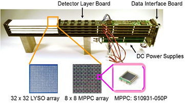
Figure 1. Photograph of a four-layer DOI detector module.
Download figure:
Standard image High-resolution image
Figure 2. Schematic drawing of a cross-section through a four-layer DOI detector (side view).
Download figure:
Standard image High-resolution imageEach detector layer board has independent front-end and signal processing circuits. In the front-end circuits, the 64-channel MPPC output signals of each detector unit are amplified and then reduced to four signals by a resistor network, and the sum signal of all 64-channel signals is generated. Each gain of the MPPCs is finely adjusted to provide the optimum bias voltage for each MPPC. In addition, a temperature sensor is located in the front of the detector layer board to compensate for temperature changes occurring with the gain of MPPCs according to the bias voltage. When a valid event is detected at one of the five units on the detector layer board, the analog signals of the unit are selected through 5:1 multiplexers in the signal processing circuits. The position signals for Anger logic calculation and the sum signal for both timing pick-off and energy discrimination are fed into the shapers and are then digitized by 10-bit analog-to-digital converters (ADCs). These digital signals are fed into a field-programmable gate array (FPGA), and signals are processed to detect γ-rays. To analyze crystal identification and energy window discrimination, look-up-tables (LUTs) were used. Additionally, timestamp data with 781.25 ps resolution were generated using a time-to-digital converter (TDC) at the moment of triggering by the timing pick-off signals. Each digital data set analyzed in the four detector layer boards was collected with a data-interface circuit board placed behind the detector module, added to DOI information and timer tag data at the indicated time interval from the scan start, and was finally transferred to a data acquisition server as 64 bits list-mode data through an optical fiber cable. Note that all single event data from each individual four-layer detector, including Compton scatter events generated between DOI crystal layers, were transferred to the data acquisition server, to allow accurate analysis of γ-ray interaction positions in post-processing.
For a typical detector unit in the first layer, the average energy resolution was 24.0%, and the coincidence timing resolution (CTR) was 850 ps FWHM with a reference detector composed of a 25 mm long truncated pyramid of BaF2 crystal (Ohyo-Koken-kagaku, Japan) and a fast photomultiplier tube (Hamamatsu H5321, Hamamatsu Photonics K.K., Japan). Further details have been described previously by Omura et al (2012).
2.1.2. Detector ring structure and gantry.
The detector ring consists of 32 DOI detector modules arranged in a shape with a 430 mm diameter and 168 detector rings with a 1.2 mm pitch. The 168 detector rings include the number of gaps equivalent to eight crystal segments, where there is a gap of 2.4 mm, equivalent to two crystal segments, between crystal arrays. The total number of crystals is 655 360. The transaxial FOV is 330 mm in diameter and the axial FOV is 201.6 mm, which are sufficient to cover a whole human brain. The major characteristics of the Hamamatsu brain PET scanner are listed in table 1. The gantry head, including the DOI detector modules, has a compact cylindrical shape with outer dimensions of approximately 740 mm in diameter and 770 mm in height. The detector head is able to move up and down, as well as forward and backward, and to tilt. Thus, the patient can take various positions, such as sitting, lying, and standing. Photographs of the gantry and the inner detector ring are shown in figure 3.
Table 1. Characteristics of the Hamamatsu brain PET scanner.
| Detector | |
| Crystal material | LYSO |
| Crystal size | 1.2 × 1.2 × 3, 4, 5 and 8 mm |
| Number of crystals | 655 360 |
| Photo-detector | 3 mm square MPPC (Hamamatsu S109231-050P) |
| Number of MPPCs | 40 960 |
| Ring geometry | |
| Number of rings | 168 |
| Ring diameter | 430 mm |
| Ring pitch | 1.2 mm |
| Transaxial FOV | 330 mm |
| Axial FOV | 201.6 mm |
| Opening diameter | 400 mm |
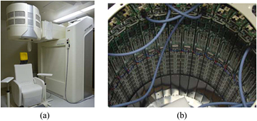
Figure 3. Photographs of (a) the gantry and (b) the inner detector ring.
Download figure:
Standard image High-resolution image2.1.3. Data acquisition.
The data acquisition server for single events consists of eight data transfer circuit boards based on a serially attached small computer system interface (SAS) and eight common server computers (IBM BladeCenter H, IBM, USA) operating on Linux. The single-event data 64-bit lists from 32 DOI detector modules are fed to the data transfer circuit boards, stored once in buffer memories, and then transferred to the server computers. Each data transfer circuit board handles the single-event data from four DOI detector modules, and transfers these data to the respective corresponding server computers. Single-event data include the crystal segment and DOI addresses, the energy and timing information (i.e. timestamp data representing the elapsed time from the start of a scan, with 781.25 ps resolution), and a valid flag indicating 'acceptable: within the range of the set energy window' or 'not acceptable out of the range of the set energy window'. In addition, timer tag data are inserted at every 0.8192 ms in the single-event data stream.
On-the-fly coincidence detections are performed by software after each single-event data set is sorted in time order, in units of 0.8192 ms, and corrected for the timing delay of each detector unit or crystal segment (Yu et al 2016). To be able to take a line of response (LOR) in the FOV, sets of two single events are analyzed within a coincidence time window of 4.3 ns, and a coincidence event is created if coincidence is detected. Random coincidence events are also created, using a delayed coincidence method. The coincidence data generated in this manner, as well as all single-event data, if necessary, are stored. Further details have been described previously by Isobe et al (2012).
2.1.4. Image reconstruction.
A list-mode dynamic RAMLA (LM-DRAMA) is implemented as the default mode for image reconstruction (Tanaka et al 2003, 2010, Nakayama et al 2005). For image data corrections, normalization, attenuation, and scatter corrections are performed. In normalization, the component-based normalization (CBN) method is used (Badawi et al 1999). The system has no transmission measurement mechanics. Thus, attenuation correction is performed using emission segmented attenuation correction (E-SAC), which involves a segmented attenuation map generated from emission data (Zaidi et al 2003). The scatter correction uses the single scatter simulation (SSS) method (Watson 2000). Random correction is performed by subtracting delayed coincidence events (Rahmim et al 2004). The dead-time loss is corrected based on an empirical relation between the total single count rate and the true coincidence count rate.
There are two reconstruction modes: a high-resolution (HR) mode for maximizing the spatial resolution performance of the system and a high-speed (HS) mode for reducing the reconstruction time. The HR-mode has an image matrix size of 512 × 512 with a 0.65 mm pixel size and 335 slices of 0.6 mm width. The HS-mode has an image matrix size of 128 × 128 with a 2.6 mm pixel size and 83 slices of 2.4 mm width. The maximum ring differences are 167 and 40, in a unit of 1.2 and 4.8 mm for the HR and HS-modes, respectively. A filtered back-projection (FBP) algorithm for image reconstruction is also implemented to evaluate the performance in spatial resolution. We used server computers as image reconstruction engines, as well as data acquisition servers.
2.2. Performance measurements
System performance was evaluated following the procedures in NEMA NU 2-2012 for a whole-body PET. The experiments described below were performed with a 4.3 ns coincidence time-window width. The energy window was set to 400–650 keV. The system CTR was 2.6 ns FWHM after employing a timing delay correction, described previously by Isobe et al (2012). The average energy resolution in the system was 23.7%, with a standard deviation of 4.2%, applying the energy correction, which was finely adjusted for each gain of the MPPCs to provide the optimum bias voltage for each MPPC.
2.2.1. Intrinsic spatial resolution.
To evaluate the intrinsic spatial resolution of the DOI detector module, coincidence response functions (CRFs) of the detector pair located at a 40 mm distance were measured. This was done by scanning a 0.25 mm diameter 22Na point source of approximately 0.7 MBq along the central line between them, at γ-ray incident angles of 0° and 22.5° to the crystal surface, in 0.12 and 0.185 mm scan steps, respectively. Each angle corresponds to the center and half positions of the transaxial FOV in the system ring configuration. The intrinsic spatial resolution measurement setup is shown in figure 4. The single-event data of the detector pair at each step position were sent to the data acquisition servers and stored in a hard disk. The acquiring times for each position were 20 and 10 min for 0° and 22.5°, respectively. After the measurements, coincidence detections were performed off-line by software and the coincidence counts were plotted as a function of the source position for each layer combination. The intrinsic spatial resolutions of the detector pair were derived from the FWHM values of the CRFs, by fitting a Gaussian function.

Figure 4. Block diagram of the intrinsic spatial resolution measurement setup for (left) γ-ray incident angles of 0° and 22.5°, and reference drawing for (right) corresponding to the system ring configuration.
Download figure:
Standard image High-resolution image2.2.2. Reconstructed spatial resolution.
The spatial resolution was assessed according to NEMA NU 4-2008 for small animal PET. A 0.25 mm diameter 22Na point source (MMS09-022: EZIP, USA) of approximately 0.4 MBq was placed at distances of 10, 25, 50, 75, 100, 125, and 150 mm from the center of the transaxial FOV with both horizontal and vertical lines, where three axial positions with the center, 1/4, and 3/8 of the axial FOV from the center of the FOV were measured. The measurement time for each position was 5 min, and more than 5 M counts were obtained. The image reconstruction was performed both in 2D FBP and LM-DRAMA in the HR-mode. The voxel sizes were 0.3 × 0.3 × 0.3 mm3 in both 2D FBP and LM-DRAMA in the HR-mode, respectively. In LM-DRAMA, the iteration number was four, and an image-based point-spread function (PSF) (Reader et al 2002) of 1.8 mm in all directions was used. To obtain FWHM values, profiles of point source images were interpolated and analyzed according to NEMA NU 4-2008.
2.2.3. Scatter fraction and count rate measurement.
The scatter fraction (SF) and count rate capability were measured using a scatter phantom that had a 20 cm diameter and 70 cm long polyethylene cylinder with a hole of 6.4 mm diameter drilled at 45 mm off-center in the plane (Data Spectrum Corporation, USA). The phantom was located at the center of both the transaxial and axial FOVs in the scanner. The initial activity of the 18F line source was 423 MBq. The scan continued over 20 h, which covered a time span of 11 half-lives, which was sufficiently low for random events and dead-time losses to be negligible. The data were acquired as single events, and on-the-fly coincidence detection was carried out during data acquisition. All coincidence data were stored on hard drives. Sinograms were generated for each 10 min acquisition frame and for each slice, where the data were separated into prompt and random data. The DOI pair sinograms of 4 × 4 combinations were gathered into a single pair, and the oblique sinograms were collapsed into a single sinogram by single-slice rebinning (Daube-Witherspoon et al 1987).
According to NEMA NU 2-2012, all frames of the measurement were analyzed into true coincidence (T) and random coincidence (R) at the count rate. The SF was also analyzed using the final acquisition data with negligible random events. Intrinsic background events due to 176Lu in the LYSO scintillator were also measured by setting the scatter phantom without activities for 16 h and using this for background corrections (Watson et al 2004). To evaluate the noise equivalent count rate (NECR), NECR-1R and 2R were calculated, although random correction for the system is practically based on direct random subtraction by delayed coincidence.
2.2.4. Sensitivity.
The sensitivity of the system was evaluated according to NEMA NU 2-2012. An 18F line source of 3 mm inner diameter and 70 cm length (Data Spectrum Corporation, USA) was aligned with the center of the transaxial FOV, and was also aligned with a 10 cm offset from the transaxial FOV as another measurement. The line source was covered by five aluminum sleeves with increasing wall thickness (1.25 mm increments), and measurements of 10 min or 12 min were repeated for each additional sleeve. The initial activity of the 18F line source in the FOV was 4.09 MBq, where the random and the dead time-losses were negligible. The acquired data were corrected according to 18F decay and 176Lu background counts estimated from 24 h measurement data without activity. The absolute sensitivity was obtained by extrapolation of the linear regression that fitted the logarithm of the count rates as a function of sleeve thickness. Sensitivity profiles for the HR and HS-modes were plotted by analyzing the data slice-by-slice.
2.2.5. Phantom studies.
To demonstrate the imaging performance, phantom studies were performed. For evaluating the spatial resolution capability in the reconstruction image, an ultra-micro hot-spot phantom (Data Spectrum Corporation, USA), placed at the center of the FOV, was measured in a 60 min scan. The initial activity was 5.0 MBq of 18F. The images were reconstructed by the LM-DRAMA in the HR-mode, which set the reconstruction parameters with 50 iterations, 40 subsets, and the voxel size in image matrix of 0.2 × 0.2 × 0.6 mm3. No attenuation and scatter corrections were employed. A 3D Hoffman brain phantom (Data Spectrum Corporation, USA), placed at the center of the FOV, was also measured with 14.1 MBq of 18F at the scan start, when the data were collected for 180 min. The images were reconstructed using the LM-DRAMA with the HR-mode, similar to those with default reconstruction parameters with four iterations. Using the values calculated under the assumption that the phantom was filled with water, attenuation and scatter corrections were employed, but no post-smoothing was applied to the images.
2.2.6. Clinical and pre-clinical studies.
Clinical and pre-clinical studies were performed at Hamamatsu University School of Medicine. All animal and human experiments were approved by the Ethics Committees of Hamamatsu University School of Medicine. In the clinical study, a healthy volunteer was scanned for 62 min after the injection of 246.4 MBq of 11C-MeQAA, a tracer for α7 nicotinic acetylcholine receptors. The images were reconstructed using the LM-DRAMA in both HR and HS-modes with four iterations. Attenuation with E-SAC and scatter corrections were employed, and images were processed with and without application of post-smoothing. As pre-clinical studies, 18F-FDG rat and mouse imaging studies were performed. A SD rat (8 weeks, 270.7 g) was scanned for 15 min after 45 min post-injection of 34.7 MBq of 18F-FDG, and a ddY mouse (7 weeks, 27.6 g) was also scanned for 60 min after the injection of 44.0 MBq of 18F-FDG. These animals were anesthetized by intravenous injection of chloral hydrate, and were then placed at the center of the FOV. The images were reconstructed using the LM-DRAMA in the HR-mode with four iterations, and the voxel size in the image matrix was 0.2 × 0.2 × 0.6 mm3. Attenuation with E-SAC and scatter corrections were employed, but no post-smoothing was applied to the images.
3. Results
3.1. Intrinsic spatial resolution
The CRFs of the center unit pair of five units in the first layer, for both 0° and 22.5°, are shown in figure 5. The averaged FWHM values in the first layer pair (layer 0–0) were 1.08 mm and 1.25 mm for 0° and 22.5°, respectively. The FWHM values in the edge region of a crystal block tend to be worse than those in the central region, especially at 22.5°. This appears to be due to the Anger logic calculation used to identify crystal segments in a crystal block. With deeper layer pairs, the FWHM values became degraded, due to the longer crystal sizes and lower coincidence counts. The averaged FWHM values with their standard deviations (SDs) for the CRFs for each layer combination are summarized in table 2.
Table 2. Full width at half-maximums (FWHMs) and standard deviations (SDs) of the CRFs of 0° and 22.5° for each layer combination.
| Layer 0–0 | Layer 1–1 | Layer 2–2 | Layer 3–3 | |
|---|---|---|---|---|
| Average (0°) | 1.08 | 1.26 | 1.33 | 1.79 |
| SD (0°) | 0.14 | 0.20 | 0.24 | 0.36 |
| Average (22.5°) | 1.25 | 1.45 | 2.02 | 3.15 |
| SD (22.5°) | 0.08 | 0.10 | 0.23 | 0.25 |
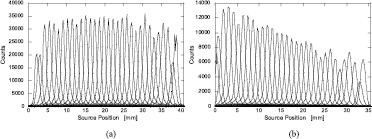
Figure 5. Coincidence response functions (CRFs) of the center unit pair of five units in the first layer, for (a) 0° and (b) 22.5°.
Download figure:
Standard image High-resolution image3.2. Reconstructed spatial resolution
Figure 6(a) shows the spatial resolutions reconstructed with 2D FBP at the axial center position. The resolutions ranged from 1.8 mm to 2.1 mm in the whole FOV. These observations indicated uniform resolutions in the whole FOV of 330 mm by adopting four-layer DOI detectors. Figure 6(b) shows the spatial resolution reconstructed with the LM-DRAMA in the HR-mode in the axial center position. The resolutions of the whole transaxial FOV for the HR-mode were uniformly around 0.9 mm. The axial resolutions in the whole FOV were also uniform, and were slightly better than the transaxial resolutions. The results for 1/4 and 3/8 of the axial FOV from the center of the FOV were not different for that in the axial center.
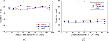
Figure 6. Reconstructed spatial resolution as a function of the distance from the center of the FOV for (a) 2D FBP and (b) LM-DRAMA in the high-resolution (HR)-mode.
Download figure:
Standard image High-resolution image3.3. Scatter fraction and count rate measurement
Figure 7 shows the total count rate capability of the system for true, random, and scatter coincidence events, including single events, as a function of the line source activity divided by the total volume of the cylindrical phantom. These data were corrected by subtracting the 176Lu background count rate of 415 cps and 381 cps for the prompt (T + S) and random coincidence rate, respectively, whereas the single background count rate was 520 kcps. The true count rate reached 249 kcps, and seemed to continue to increase. The single count rate also increased over 25 Mcps, suggesting that the dead-time losses were slight. This indicates that the single-event data acquisition system worked well even in the high-count rate regions. The NECR_1R and 2R are shown in figure 8. The peaks of NECR_1R and 2R were 44.7 kcps at 17.5 kBq ml−1 and 27.9 kcps at 11.9 kBq ml−1, whereas SF was 48.3% and 47.2%, respectively.
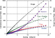
Figure 7. Count rate capability as a function of the line source activity divided by the total volume of the 70 cm cylindrical phantom.
Download figure:
Standard image High-resolution image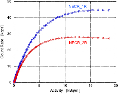
Figure 8. Noise equivalent count rate (NECR) as a function of the line source activity divided by the total volume of the 70 cm cylindrical phantom.
Download figure:
Standard image High-resolution image3.4. Sensitivity
The absolute system sensitivity values were corrected for 176Lu background, and only the activity located in the FOV was taken into account. In the HR and HS-modes, the absolute system sensitivity values were 21.4 cps kBq−1 (2.14%) and 23.7 cps kBq−1 (2.37%) for the center and 10 cm off-center positions of the FOV, respectively (table 3). The background count rate for true coincidence was 105 cps. The distributions of the slice sensitivity for the center and 10 cm off-center positions for the HR and HS-modes are shown in figure 9. The distributions for both HR and HS-modes took on a triangular shape, because almost all LORs in a ring difference were used. The maximum sensitivity per slice in the HS-mode was approximately four times higher than that in the HR-mode, since the defined slice thickness (2.4 mm) in the HS-mode was four times thicker than that (0.6 mm) in the HR-mode.
Table 3. System absolute sensitivities for the center and 10 cm off-center of the FOV in the high-resolution (HR) and high-speed (HS)-modes. Both modes show the same values, because almost all LORs were used in a ring difference in each mode.
| HR-mode | HS-mode | |
|---|---|---|
| Center | 21.4 cps kBq−1 | 21.4 cps kBq−1 |
| 10 cm off-center | 23.7 cps kBq−1 | 23.7 cps kBq−1 |
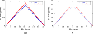
Figure 9. Distributions of the slice sensitivity for the center and 10 cm off-center positions for the (a) high-resolution (HR)-mode and (b) high-speed (HS)-mode.
Download figure:
Standard image High-resolution image3.5. Phantom studies
Figure 10 shows a reconstructed image of an ultra-micro hot-spot phantom acquired in 60 min with injection of 5.0 MBq of 18F. The 1.35 mm and higher hot-spots were clearly separated. The line profiles across both 1.35 mm (line a–a' in figure 10) and 1.75 mm (line b–b') hot-spots are shown in figure 11. This may be appropriate, given the results of section 3.2 for reconstructed spatial resolution. Figure 12 shows a reconstructed slice image of a 3D Hoffman phantom acquired in 180 min with injection of 14.1 MBq of 18F. The total counts of the images used for reconstruction were 693 M counts. Good quality images with high resolution were obtained.

Figure 10. Image of an ultra-micro hot-spot phantom.
Download figure:
Standard image High-resolution image
Figure 11. Line profiles of the ultra-micro hot-spot phantom across (left) 1.35 mm (line a–a') hot-spots and (right) 1.75 mm (line b–b').
Download figure:
Standard image High-resolution image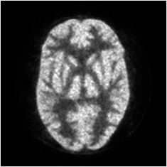
Figure 12. Slice image of a 3D Hoffman brain phantom.
Download figure:
Standard image High-resolution image3.6. Clinical and pre-clinical studies
Figures 13(a)–(c) show human brain images of a slice from a healthy volunteer given 11C-MeQAA, with reconstruction (a) in the HR-mode without post-smoothing, (b) in the HR-mode with post-smoothing, and (c) in the HS-mode without post-smoothing, respectively. All 62 min acquisition data were used for the reconstruction. The total true coincidence counts, including scatter events, for image reconstruction were 534 M counts. The HR-mode image (a) appears to be of high resolution, if slightly noisier than the HS-image (c), given the small voxel size of the image matrix and lack of post-smoothing. Therefore, block-matching and 4D filter (BM4D) (Maggioni et al 2013) was applied to the image in (a) for post-smoothing, to derive a denoising image (b). Figure 14 shows 18F-FDG (a) rat and (b) mouse images in the transverse, coronal, and sagittal directions. For image reconstruction, all 15 min acquisition data for the rat and the last 15 min of data from among the 60 min acquisition data for the mouse were used. The cerebral cortex in the rat brain was clearly observed, and that in the mouse brain was visible.
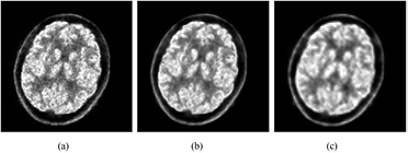
Figure 13. The same brain slices of 11C-MeQAA PET images of a healthy volunteer using different reconstruction modes: (a) high-resolution (HR)-mode, (b) HR-mode plus post-smoothing with a block-matching and 4D filter, (c) high-speed (HS)-mode.
Download figure:
Standard image High-resolution image
Figure 14. (a) Rat and (b) mouse images taken with 18F-FDG. The coronal and sagittal images are reduced to 60% of the transverse image and displayed.
Download figure:
Standard image High-resolution image
4. Discussion
We developed a new high-resolution brain PET scanner with four-layer DOI detectors. One of its main features is its high-resolution capability, as compared to previously developed brain PET scanners; this was made possible by using a fine pitch (1.2 mm) of crystal segments with a size compatible with pre-clinical PET scanners. The PET scanner is also the first completed system for clinical use that employs multi-layer independent readout detectors. This feature makes it possible to detect γ-ray interaction positions accurately by detecting Compton scattering events.
The detector module consists of four independent layer detectors comprising MPPCs and finely segmented LYSO scintillator arrays with a 1.2 mm pitch. This module also includes front-end and signal processing circuits for crystal identification, energy discrimination, and timing detection. Thus, the module has all the functions required for γ-ray detection, although its length is increased by 430 mm. Compared to the results of the individual detector module performance (Omura et al 2012), the average energy resolution in the proposed system was 23.7%, similar to that of a single detector unit, but the CTR performance was degraded. The system CTR was 2.6 ns FWHM after employing a timing delay correction (Isobe et al 2012). From the result of a single detector unit, we can roughly estimate that the ideal system CTR is approximately 1.4 ns FWHM. Therefore, there is still scope for improvement of the system CTR by adjusting the timing delay.
We did not make use of time-of-flight (TOF) information for this brain PET scanner. Therefore, the front-end electronics, timing pick-off, and TDC circuits were not optimized for TOF performance, although MPPCs have potentially high timing resolution capability (Gundacker et al 2013). A short scintillator crystal length (3, 4, 5 and 8 mm) and an independent readout scheme would allow improved TOF performance, because of a reduced photon travel-time spread in the scintillator crystal. Thus, the system would be suitable as a TOF-PET scanner, if the detector circuits were optimized for TOF performance.
The internally focused laser processing technique allowed us to fabricate fine pitch scintillator arrays of 1.2 mm, which afforded the PET scanner with high-resolution capability. This technique was also effective for reducing the fabrication time and cost required for preparing 640 pieces of a scintillator array for system construction, since we developed a prototype laser processing machine, which can process multiple pieces simultaneously. The drawback of this technique is the markedly increased optical cross-talk through the micro-crack walls produced by laser processing as compared to using a reflector sheet, such as enhanced specular reflector film (3M, USA), resulting in degradation of the positional separation of the crystal segment in the array. However, 3, 4, 5, and 8 mm scintillator thicknesses for this module were sufficient to separate the segments; the 2D position histograms for these were shown previously by Omura et al (2012). Compared to using a pure monolithic scintillator for a PET detector (Schaart et al 2009, Tabacchini et al 2017), the proposed system has the advantages that the calibration of the detector is easy and sufficient resolution of positions can be obtained based on Anger logic calculation, which can be achieved using simpler signal processing circuits than that achieved by using light spread function. It has the disadvantages that the position resolution is limited by the processed pixel size and incurring of laser-processing cost.
The detector resolution was evaluated by measuring the CRFs and the average FWHM value of 1.08 mm and 1.25 mm for 0° and 22.5° in the first layer pair, respectively, were obtained. The system spatial resolution was less than 2.1 mm FWHM across the whole FOV, measured according to NEMA NU 2-2012. In the HR-mode when using LM-DRAMA, 1.35 mm hot-spots in an ultra-micro hot-spot phantom were clearly separated. To evaluate the imaging capabilities, we performed measurements on a 3D Hoffman phantom, a human brain, and small animals. We obtained clear images, as shown in figures 12–14.
We implemented a single-event data acquisition method with on-the-fly coincidence detection by software built into this PET scanner. The advantage of single-data acquisition for PET is that it allows the ability to use full information of physical parameters for image reconstruction. The timing information of each single event provides us with the optimum timing window and the possibility to adjust for timing delays of each detector, using software. The energy information can be applied for scatter correction, although it was not used in the present study, and may not be used as long as only list-mode data acquisition is implemented. Additionally, there is considerable flexibility in arranging the ring structure, because there is no need to develop coincidence detection circuit boards adopting the ring structure. The count rate capability in the system was evaluated using a 70 cm long cylindrical phantom according to NEMA NU 2-2012. The maximum count rate exceeded 25 Mcps and 2.3 Mcps for single events and coincidence events (prompt and random), respectively, and can potentially reach even higher values. The dead-time losses in singles would be primarily caused if the 5:1 multiplexer selected one unit among the units irradiated γ-rays in the detector layer board, although this could be fairly suppressed by using independent readout detectors. Apart from that, the maximum count rate would be limited by the data acquisition transfer speed if the singles would not be saturated by the dead-time losses, and approximately 120 Mcps was estimated to be the maximum single count rate, assuming that the count rate was uniform for each detector module. The on-the-fly coincidence detection by software operated successfully, without any data loss, sufficiently so for clinical brain studies using 11C-MeQAA injection, because the maximum single count rates in the studies were less than 25 Mcps. However, attempts should be made to assess this by 15O water studies, which typically use very high injection activities. The real-time coincidence detection engine was created by common server computers using software. If the single count rate is considerably increased, coincidence detection may not follow. The computer power; however, has increased exponentially annually; thus, software coincidence detection is likely to become routine. The peak NECR_2R was 27.9 kcps at 11.9 kBq ml−1. This value is lower than that of high resolution research tomograph (HRRT) and jPET-D4 brain PET scanners, mainly due to the 3/4 shorter axial FOV.
Since the detector module is designed for a four-layer DOI detector, where each layer operates independently, it is possible to analyze Compton scatter events to obtain a first interaction point in a multiple scattering event between different layers of an incident γ-ray, using the energy information and time stamp data in the single list data. We had set the energy window to 400–650 keV. To analyze Compton scatter events, the lower-level energy discrimination (lled) is, however, necessary to set the window at 100 keV or less, i.e. as low as possible. Future studies will face several challenges, such as reducing electronic noise to lower the lled, as well as eliminating the 176Lu background, and real-time processing to detect the first interaction point. When these challenges have been addressed, the performance, especially the sensitivity and spatial resolution, will be markedly improved.
5. Conclusion
We developed a new high-resolution brain PET scanner, using four-layer DOI detector modules. The DOI detector module consists of MPPCs, finely segmented LYSO scintillator arrays with a 1.2 mm pitch, and signal processing circuits including front-end electronics. This structure provided the scanner with high-resolution capability. The spatial resolution in the HR-mode was about 1.0 mm in the whole FOV, and 1.35 mm hot-spots in the ultra-micro hot-spot phantom were clearly separated. Imaging performance was demonstrated in a human brain study and pre-clinical studies, and excellent images were obtained. Coincidence detection was performed by on-the-fly software using single-event data. Single-event data acquisition and on-the-fly software coincidence detection worked well, even in a high-count rate condition. Therefore, dynamic PET studies using 11C-labeled tracers, which are injected at higher activities, will be applicable. These results indicate that the new brain PET scanner has satisfactory performance in both clinical and pre-clinical studies. Imaging quality and the investigated characteristics should be improved in future studies.
Acknowledgment
The authors gratefully acknowledge Dr Y Ouchi, Dr Y Magata, and other staff of the Preeminent Medical Photonics Education & Research Center, Hamamatsu University School of Medicine, for their assistance in system evaluation and in clinical and pre-clinical studies. The authors also acknowledge the staff of the Hamamatsu Development Center and Central Research Laboratory for their cooperation in the system's construction and evaluation. This work was supported in part by a Grant from the New Energy and Industrial Technology Development Organization, Japan.