

Abstract
We propose an original technique for the grating metasurfaces fabrication by low-power ultraviolet laser treatment of fluorinated graphene (FG) films with the focus on terahertz applications. The laser treatment reduces dielectric FG to its conductive counterparts, increasing DC conductivity to 170 S·m−1 for treated areas. The electromagnetic response of the grating metasurfaces studied by THz time-domain spectroscopy in the 100 GHz–1 THz frequency range demonstrates enhanced resonant transmittance through metasurfaces. The intensity and position of transmittance peak could be tuned by changing the metasurface geometry, i.e. the period of the structure and width of the reduced and unreduced areas. In particular, the decrease of the reduced FG area width from 400 to 170 μm leads to the shift of the resonance peak from 0.45 THz to the higher frequencies, 0.85 THz. Theoretical description based on the multipole theory supported by finite element numerical calculations confirms the excitation of the dark state in the metasurface unit cells comprising reduced and unreduced FG areas at resonance frequency determined by the structure geometrical features. Fabricated metasurfaces have been proved to be efficient narrowband polarizers being rotated by 50° about the incident THz field vector.
Export citation and abstract BibTeX RIS
1. Introduction
The explosive growth of interest to exploring the Terahertz (THz) range stimulates further search for new, relatively cheap, scalable, compact, fast, tunable THz components (polarizers, modulators, filters, focusing elements) that can be easily integrated with the existing systems [1, 2]. Today, THz optics is based in large extent on the periodic metal metasurfaces, sensitive to the phase and polarization of the incident radiation [3–10]. The electromagnetic response of such structures is fully determined by periodicity of the individual elements, their shape and size, whereas conductivity of the metal elements is almost perfect and non-adjustable. Lack of tunability of the conductivity of metal components can be overcome by using instead a wide palette of carbon nanomaterial or graphene [11, 12]. Their conductivities could vary in a very broad range, and could be also sensitive to external stimuli. It gives thereby one more degree of freedom to the carbon-based metasurfaces design versus their THz performance.
Polarizers based on doped graphene (Gr) [13] are significantly smaller as compared to similar devices based on metallic structures. Therefore, all-carbon THz components, which complex meta-structure can be created in one synthesis/post-processing technological cycle are highly desirable. While pristine Gr is nearly transparent for THz radiation, [14] its doped or functionalized counterparts demonstrate high [15] or almost perfect absorption [16–18].
Fluorinated graphene, [19] i.e. a highly stable graphene nanosheet in which a certain amount of C atoms is covalently bonded to F atoms, [20] is one of the most studied chemically functionalized derivatives of Gr. Fluorination signicantly tailors the electronic and optical properties of Gr towards either a high-quality insulator [21] with a wide bandgap of up to 3 eV [19] or semi-metal with AC conductivity at 600 GHz up to 90 × 103 S·m−1 [22]. The later can change by several orders of magnitude with fluorine content [23]. Thus, a graphitic matrix partially structured by fluorination is a simple platform for a 'all-carbon' metasurface fabrication combining conductive and insulating elements.
One of the most promising method of such a metasurface formation is ultraviolet laser profiling of dielectric fluorinated graphene (FG), leading to its reduction to conductive phase. In this work we study the THz performance of the Gr/FG grooves-type grating metasurface with electric field oriented along and transverse to the patterned areas. We demonstrate that proposed approach of the all-carbon' metasurface fabrication combining fluorination of graphitic material followed by reduction and patterning with ultraviolet (UV) laser can be successfully used for creation of thin, light, flexible polarization-sensitive THz components.
Moreover, all-carbon gratings have been perfectly used for creating nearly transparent THz surfaces [24–29]. One of the most promising strategies to fabricate the metasurface supporting enhanced transmittance is utilizing relatively low conductive individual elements. This allows reducing radiating losses, exploiting e.g. dark state phenomenon [30–34]. These nonradiating states originate from a vanishing net of multipoles due to destructive interference between states excited in the different parts of individual elements of the metasurface [35].
In this paper, we demonstrate the effect of enhanced transmittance in the Gr/FG grooves-type grating metasurface in THz regime due to a resonance dark state excitation in unit cells, and prove experimentally that this metasurface could be used as a narrow-band polarizer/filter of THz radiation, with tunable properties versus the metasurface lattice parameters and peak position. At the same time, the combination of the high-quality factor of the resonance, as well as unique properties of FG, which can be changed under the UV radiation, makes the FG-based metasurface an excellent platform for fabrication highly sensitive and efficient tunable THz components.
2. Design of Gr/FG grating metasurfaces
For this aim, we propose the metasurfaces based on Gr/FG grating and perform numerical simulation of the electromagnetic (EM) spectra of such metasurfaces using the Comsol Multiphysics software. The schematic representation of considered grating and its interaction with electromagnetic waves are presented in figure 1. Grating structure consists of periodic along the x axis conductive arias made of reduced FG (labeled as Gr) and dielectric arias made of FG. The dielectric permittivity of Gr was described by the Drude model with a DC conductivity of 170 S·m−1. The thickness of Gr and FG areas were set 45 μm and 9 μm, respectively. In the numerical calculations thin (42 μm) nondispersive dielectric layer (kapton tape) with permittivity ε = 3.3 was considered as a substrate. The periodic boundary conditions were used along x - and y- directions, while open boundary conditions were set along z - directions. The incident wave was defined as x (TM, E⊥)- or y (TE, E∥)- polarized plane wave. The calculated transmittance spectra at normal incidence (i.e. ϕ = θ = 0°, were ϕ and θ are rotation angles around x - and y- directions, respectively) for the structure with width of the reduced area (a) of 200 μm and period (Λ) of 400 μm are presented in figure 2 (solid curves).
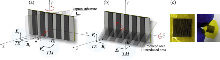
Figure 1. Schematic representation of the one-dimensional the Gr/FG grating metasurface: (a) rotation around y axis, (b) rotation around x axis. Λ is the period of the grating metasurface, a is the width of the conductive area (Gr), tsub is the thickness of dielectric layer, (c) Photographs of the experimentally obtained Gr/FG grating metasurface.
Download figure:
Standard image High-resolution image
Figure 2. THz transmittance spectra of Gr/FG metasurfaces with different widths of the reduced and unreduced areas: (a) TE-polarized wave and (b) TM-polarized wave. On the inset in (b): THz transmittance spectra of the initial FG film, the reduced area of FG film and kapton tape. Measured data (points) and simulation (solid curves) at normal wave incidence.
Download figure:
Standard image High-resolution imageIn the framework of the effective Bragg-cavity model [36–38], for sub-wavelength regime (λ > 2 · a, where λ is the wavelength of the incident plane wave) (see inset in figure 2(a)) at normal incidence it easily to analytically show that there is only one propagation mode outside of the grating, which corresponds to zero order transmittance (m = 0). All the other higher order Bragg's modes (m ≠ 0) are evanescent outside the Gr/FG grating metasurface. Moreover, in the sub-wavelength regime, there are no propagation modes inside the FG layer (we consider grating structure without dielectric substrate). Presence of thin dielectric layer leads to supporting a propagating mode of higher Bragg order (guided-state, under condition λ = n · Λ, where n is the reflective index of thin dielectric layer) [39]. The constructive interference between the propagating m = 0 mode and higher order modes is responsible for the THz transmittance peak formation for TE -polarized plane wave. The EM field distribution for electric and magnetic fields calculated in the vicinity of resonance peak is presented in figures 3(a), (b) and confirms the discussion above.

Figure 3. EM field distribution in the vicinity of resonance peak (0.65 THz) for TE polarized plane wave: (a) electric and (b) magnetic fields. The incident wave comes from z > 0 side. (c) Scattering cross-section of leading multipoles excited in the unit cell of metasurface (d) and in single unit cell. The numerical simulation was performed for the structure with a = 200 μm and Λ = 400 μm.
Download figure:
Standard image High-resolution imageWe choose the parameters of metasurface in order to provide multipoles interactions between inclusions for the dark state manifistation. The future analysis of nature of the transmittance resonance in the TE-polarized plane wave was carried out by performing multipole decomposition of currents excited in each unit cell [40, 41]. Multipole analysis is an effective tool in electrodynamics for expanding the radiation field of a random source into an infinite series of Cartesian or spherical harmonics in the long wavelength approximation [42]. The Cartesian multipoles inside unit cell were calculated by integration the induced current density (j) over the entire volume of unit cell [33]. Scattering cross-section for electric P, magnetic M dipole moments as well as quadrupoles moments (electric (Qe ) and magnetic (Qm ), respectively) are presented in figure 3(c) [42]. All multipole states are expressed by integrals over the unit cell volume with different moments of the current density j, where i is an imaginary unit, ω is angular frequency, r is the vector from the origin of coordinates to an arbitrary point of the current distribution area and α, β = x, y, z:


Indeed, the EM response of Gr/FG metasurface for TE polarized incident wave is determined by electric dipole P and suppression of other multipoles. Moreover, in the vicinity of the transmittance peak at 0.65 THz the scattering cross-section related to electric dipole P contribution has a dip (figure 3(c)), which indicates the subradiant nature of exited states (dark state) [35]. In support of this statement we calculated scattering cross-section of multipoles for a single unit cell, which character sufficiently differs from scattering on whole metasurface. In the case of a single unit cell the resonance dip is not observed (figure 3(d)). Thus, we can conclude that the reason of the dark state is the interaction between unit cells of the metasurface, i.e. associated with lattice effect of multipoles and the enhanced transmittance of the metasurface.
It is worth noting that the total transmittance of electromagnetic waves through the metasurface arises due to suppressed of dissipative and radiating losses. Dissipative losses are originated due to the presence of conducting inclusions, while radiating losses appear due to strong scattering from the structure. In case of Gr/FG metasurfaces low scattering and low radiating losses lead to the enhanced transmittance for the grating structure, whereas dissipative losses of FG reduce the transmittance up to 0.6. However, we can expect the higher transmittance after optimization of Gr/FG metasurface geometry.
Although, one can be confused by the difference between dark mode and dark state, we are pointing out similarities between them in our case. In our system, we cannot directly excite single fluorinated graphene element and dark mode is result of coupling between elements in the metasurface. At the same time, the dark state is result of destructive interference between resonances of individual fluorographene elements placed in the metasurface. Thus, our effect can be classified as dark mode and dark state simultaneously.
3. Materials and methods
3.1. Metasurface fabrication
In order to experimentally proof the enhanced transmittance through the metasurface, we fabricated samples with dimensions obtained in simulations.
Purified natural graphite was fluorinated in a Teflon reactor in saturated vapors of BrF3/Br2 mixture at room temperature. The concentration of BrF3 in Br2 was 10 wt% and the reaction time was 30 d. Details of the synthesis procedure for preparing partially fluorinated graphite are described elsewhere [43].
Thin films were prepared as follows. Fluorinated graphite powder (ca. 4 mg) mixed with toluene (10 μ) was ground in an agate mortar and then bath-sonicated (100 W, 35 kHz) in toluene (40 ml) for 30 min. FG suspension (0.1 mg ml−1) was filtered through nitrocellulose (NC) membrane with a pore size of 0.45 μm. A thin film with the thickness of around 9 μm and sheet density of 0.4 mg·cm−2 was obtained from the 40 ml suspension. The NC membrane with a deposited FG film was cut into pieces of 10 × 10 mm2 and applied to a kapton tape (42 μm thickness) which was used as a substrate for grating structures. The kapton tape was used as it is transparent for THz radiation. At the last step, the NC membrane was mechanically detached from the FG film.
The patterning of FG films was carried out using an engraver equipped by a low-power (100 mW) UV laser (380 nm). The processing was carried out by successive linear passes of the laser beam over the surface of the sample at a speed of 7.5 mm·s−1. The lines were applied in parallel with a step approximately 50 μm, while complete overlap of the treated surface was achieved, since the diameter of the focused laser spot was about 70 μm. It is worth noting that the efficiency of laser treatment depends on both laser power and processing time.
We obtained a set of samples labeled as FG-1, FG-2, FG-3, FG-4 (see table 1) with different width of as-it-is FG and reduced laser-treated FG areas.
Table 1. Structural parameters of Gr/FG samples.
| Sample name | Width of reduced area, μm | Width of unreduced area, μm |
|---|---|---|
| FG-1 | 400 | 200 |
| FG-2 | 300 | 170 |
| FG-3 | 200 | 200 |
| FG-4 | 170 | 120 |
3.2. Structural characterization
The structure and composition of Gr/FG grating metasurfaces were examined by scanning electron microscopy (SEM, Hitachi S-4800 microscope) and energy-dispersive x-ray spectroscopy (EDX spectrometer Bruker Quantax 200). Cross-section SEM images were used for film thickness investigation. Raman spectra were collected by Nanofinder High End (Tokyo Instruments) confocal system at room temperature with a 600 lines mm−1 grating. The measurements were performed using an excitation at 473 nm. A 100x objective with NA = 0.95 was used. The spot size on the sample surface was 0.75 μm. To avoid sample degradation, the exposition time was 30 s. The spectral resolution was about 2–3 cm−1.
DC resistance of samples was tested using a MicroXact probe station connected to a Keithley SourceMeter 2636 B. The experiments were carried out in a four-point configuration under ambient conditions. Silver paste was used to improve the electrical contact to the film.
3.3. THz characterization
The THz transmittance measurements were carried out at room temperature on a commercially available THz time-domain spectrometer T-SPEC Ekspla (Lithuania), in which linearly polarized THz radiation with a frequency range up to 2 THz is generated by a photoconductive antenna under irradiation with 50–150 fs long laser pulses at a wavelength of 1050 nm. The samples were placed on the focal point of the parabolic mirrors where the THz beam spot diameter was around 3.5 mm. The measurements have been performed at normal incidence in the cases when electric field parallel E∥ (TE-polarized wave) and perpendicular E⊥ (TM-polarized wave) to grating axis, and analogically at sample rotation in horizontal and vertical planes (figures 1(a), (b)). The transmittance spectrum was defined as the intensity ratio of transmitted THz wave though sample and to the intensity THz wave in free space. In order to increase the signal to noise ratio, each spectrum was averaged over 1024 measurements. To measure the angle-dependent THz spectra the special rotation stage was adopted as a sample holder.
4. Results
4.1. Materials structure
The optical microscopy images of the obtained Gr/FG metasurface on kapton tape substrate are presented in figure 1(c). From the SEM images shown in figure 4 it can be seen that the surface of unreduced area has a platelet structure [44] with a thickness of about 9 μm (figure 4(b)). As evidenced from cross-section measurements (figure 4(c)) the thickness of the reduced area is about 45 μm. The reduced area has a typical 'worm like' lamellar structure, indicating a high degree of graphene layers exfoliation due to laser treatment [44].

Figure 4. SEM images of FG-1 metasurface: (a) top view, (b) cross-section view of the reduced and unreduced areas, (c) cross-section view of the reduced area at higher magnification. EDX element mapping of the FG-1 sample: (d) top view and (e) cross-section view. Red, blue and green colors correspond to F, C and Si, respectively, (f) Raman spectra of the as-it-is part of the initial FG film (black line) and reduced area of grating structure (red line).
Download figure:
Standard image High-resolution imageThe data of EDX analysis of the initial FG film and the film areas after laser treatment are collected in table 2. Fluorine content in the initial unreduced area of FG is 21 at.%. UV laser treatment dramatically decreases C/F ratio from 0.34 to 0.06 and increases C/O ratio from 0.18 to 0.21. Figures 4(d), (e) show the overlay EDX element mapping (top view (d) and cross-section view (e)) of FG-1 metasurface, in which F and C elements are marked by red and blue colors, respectively. The EDX results demonstrate a uniform distribution of F in the sample and fluorine enrichment of the fluorinated graphene areas. Similar results were obtained for other samples.
Table 2. Content (at.%.) of main elements in reduced and unreduced areas of FG-1 sample determined by EDX spectroscopy.
| C | F | O | |
|---|---|---|---|
| Unreduced area | 66 | 22 | 12 |
| Reduced area | 78 | 5 | 17 |
Figure 4(f) compares Raman scattering spectra of as-it-is and laser treated areas of FG film. Spectrum of original FG contains D-peak at 1363 cm−1 and G-peak at 1582 cm−1 and exhibits a very intense luminescence in accordance with previous experiments. The D-peak corresponds to the scattering on structural defects of the hexagonal graphite lattice. In case of FG films these defects are introduced by the attachment of fluorine atoms [45]. The crucial changes in the shape of Raman spectrum are observed for the laser-treated FG area, which are reflected in a decrease of FWHM (Full width at half maximum) of all peaks and clear appearance of D'-peak at 1620 cm−1. For the reduced area we observe a decrease in the ratio of intensities of D-peak (ID ) and G-peak (IG ) to 0.79 as compared the value of 0.84 obtained for the initial FG film. This is due to detachment of fluorine under the UV laser treatment. A large FWHM value of the 2D-peak (70 cm−1) indicates the multilayered nature of exfoliated graphene. The intensity of 2D-peak increases after laser treatment, which confirms defluorination of films.
We can conclude that the interaction of laser beam with the surface of FG film effectively removes fluorine while retaining graphene carbon skeleton [46, 47]. Restoration of Gr areas in the FG film increases its conductivity up to 170 S·m−1. Indeed, the DC measurements show that initial FG film exhibits insulating behavior.
4.2. Terahertz probing
FG films deposited on kapton tape substrate are almost transparent in the THz frequency range (T ∼ 80% at 0.5 THz, see inset in figure 2(b)), whereas the reduced 45 μm thick FG film transmits not more than 20% of THz radiation. Figure 2 shows the THz transmittance spectra of Gr/FG metasurfaces measured at the normal incidence for two different polarizations of the THz radiation. The cases corresponding to the E∥ and E⊥ are presented in figures 2(a), (b), respectively. The resonance peak position, intensity and overall spectral structure are in good agreement with the simulation data. In the case of E∥, the transmittance spectra exhibit a strong resonance peak, which shifts to the high frequency range (from 0.44 THz for FG-1 to 0.85 THz for FG-4) as the width of the reduced area decreases. The frequency position of the observed THz resonance peak in TE polarization is mainly determined by geometry of the system (periodicity of the grating, the slit width, the thickness and electromagnetic properties of the thin dielectric layer). However, the grating thickness is large compared to the skin depth of reduced graphene area, which in turn depends on C/F ratio. On the other hand, due to the presence of dielectric losses the transmission efficiency for the E⊥ wave decreases with frequency (figure 2(b)) and the transmittance spectra do not demonstrate any resonance peaks.
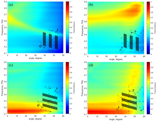
Figure 5 shows the measured dependence of transmittance spectra of FG-3 versus the incidence angle for both TE and TM polarized waves. The rotation was done around horizontal (versus ϕ) (figure 1(a)) and vertical (versus θ) planes (figure 1(b)). In case of E∥ (figure 5(a), (b)), the position of resonance peak shifts to lower frequencies with increasing ϕ (from 0.65 THz for ϕ = 0° to 0.42THz for ϕ = 50°) and to higher frequencies with increasing θ (from 0.65 THz for θ = 0° to 0.8THz for θ = 50°). Moreover, the peak intensity as well as peak FWHM decrease when rotation occurs in horizontal plane (figure 5(a)) and increase when rotation takes place in vertical plane (figure 5(b)). As follows from figures 5(c), (d), for E⊥ the transmittance decreases down to 10% with increasing ϕ and does not significantly depend on θ. Thus, we conclude from the analysis of the data presented in figure 5, that fabricated grating structure could be considered as a narrow-band polarizer/filter as rotation on the angle 50° in relation to the incident THz radiation makes it transparent for E∥ and opaque for E⊥ waves.
Figure 5. Measured data for FG-3 grating metasurface. Dependence of (a), (b) TE-polarized wave and (c), (d) TM-polarized wave transmittance through the metasurface on frequency and incidence angle.
Download figure:
Standard image High-resolution image
5. Conclusions
In conclusion, we studied theoretically and experimentally the Gr/FG grooves-type 'all-carbon' grating metasurface for THz applications. We demonstrated the enhanced transmittance of THz waves through considered grating structures due to lattice dark state excitation. By optimizing the grating parameters, i.e. the widths of the reduced and unreduced areas, we could approach to the THz component sensitive to the incident wave polarization, which makes it appealing for practical applications as polarizers/filters of THz radiation. The obtained parameters of Gr/FG metasurfaces are close to the parameters demonstrated by metal-dielectric grids. However, the presented technique has a much wider freedom through variation of the film thickness, patterned profile, composition and as a result components conductivity and dielectric properties, which cannot be achieved by the metal-based structures. In addition, laser mapping allows to quickly create textures of various designs without using shadow masks or templates to form a metal profile. The use of 'classical' metals in such metasurfaces leads to additional undesirable losses, as well as to difficulties in the development of flexible THz components [48].
Acknowledgments
We are thankful to Alexey Basharin and Polina Kuzhir for fruitful discussions and advice on modelling and results interpretation. This work was supported by BRFBR grant number F21RM-057 and the Ministry of Science and Higher Education of the Russian Federation within the governmental orders for Nikolaev Institute of Inorganic Chemistry (project 121 031 700 314-5).
Data availability statement
All data that support the findings of this study are included within the article (and any supplementary files).
Author declarations
Conflict of interest
The authors have no conflicts to disclose.