

Abstract
In this paper, we propose a method to improve the performance of TiN/Hf0.5Zr0.5O2 (HZO)/TiN Nano-capacitors used in memory devices. Instead of direct fabrication of the TiN/HZO/TiN device, our method involves an intermediate step in which W metal is used as a capping material to induce a large in-plane tensile strain during rapid thermal annealing, resulting in a total suppression of the monoclinic phase and the appearance of the ferroelectric phase. Consequently, after removing the W capping electrode through an etching process and the post-deposition of a TiN top electrode at room temperature, a high remnant polarization of approximately 40 μC cm−2 and a 65% increase of coercive field were obtained. Moreover, the leakage current was reduced by an order of magnitude compared to the normal TiN/HZO/TiN capacitor; this result is attributed to the presence (absence) of the W/HZO (TiN/HZO) top interface during thermal annealing. The formation of a TiOx interfacial layer at elevated temperatures, which pulls oxygen from the HZO layer, resulting in the formation of oxygen vacancies, is the main cause of the high leakage current through the TiN/HZO/TiN stacks. It was confirmed that the re-capped TiN/HZO/TiN capacitor has a comparable endurance to a normal capacitor. Our results offer the re-capping process as a promising approach to fabricating HfO2-based ferroelectric memory devices with various electrode materials.
Export citation and abstract BibTeX RIS
Introduction
Since the discovery of Si-doped HfO2 ferroelectrics [1], studies on the effect of various parameters to achieve a reliable HfO2 device have been actively conducted [2–4]. HfO2-based thin films are of great interest for use in ferroelectric random-access memories [5–7], ferroelectric field effect transistors [8–10], and ferroelectric tunneling junctions (FTJs) [11–13] owing to their numerous advantages such as simple structure, strong binding energy between the oxygen and transition metal ions, wide bandgap (approximately 5.3–5.7 eV), small deposition thickness (order of nm), relatively low crystallization temperature, and more importantly, compatibility with current complementary metal oxide semiconductor technologies and suitability for integration within 3D nanostructures [14, 15].
In terms of data retention and memory window (MW), high remnant polarization (Pr) and coercive field values (Ec) are required, because the theoretical MW is 2Ec × tFE (where tFE is the ferroelectric thickness) [8, 16]. Moreover, by increasing Ec, the early-stage polarization decay can be prevented [17]. On the other hand, in FTJs, as Pr increases, the tunneling electroresistance ratio increases, and a high Ec is required for read-voltage margin [18]. Therefore, various studies on obtaining high Pr and Ec values have been carried out [19–21].
Bulk HfO2 crystallizes in a monoclinic (P21/c) structure (m-phase) under ambient conditions [22]. A martensitic phase transformation from monoclinic to tetragonal (P42/nmc) (t-phase) is observed at approximately 1700 °C. A further increase in temperature to approximately 2200 °C causes a diffusionless tetragonal-to-cubic Fm m (c-phase) transition [22]. These transition temperatures can be substantially adjusted by doping, mechanical stress, or surface manipulation, and the high-temperature phases are practically achieved in HfO2 thin films at room temperature (RT) [23–33]. A non-centrosymmetric polar orthorhombic metastable phase (Pca21, o-phase) is believed to be the structural origin of ferroelectricity in HfO2-based thin films [22, 34]. Pca21 is extremely close in free energy to the equilibrium nonpolar phases [22]. Therefore, tuning the experimental conditions may stabilize this polar polymorph.
Zr appeared to be one of the most appropriate dopants to induce strong ferroelectric properties in the HfO2 thin film [4]. It was shown that Hf0.5Zr0.5O2 (HZO) thin film is a promising candidate for fabricating metal–insulator–metal (MIM) devices with excellent ferroelectric properties [15].
In addition to the effect of doping materials, the ferroelectric properties of HfO2-based films are substantially affected by capping electrodes [35, 36]. Not only do the electrochemical properties of different metal electrodes cause a serious problem for obtaining a perfect metal/insulator interface without the formation of an interfacial layer, but also the thermal expansion coefficient (TEC) of capping materials is a crucial parameter for inducing the ferroelectric phase into the HfO2-based thin film [37, 38]. Various materials, such as titanium nitride (TiN) [6], tungsten (W) [39], ruthenium (Ru) [40], and platinum (Pt) [41], have been used as electrodes for HZO films. Among them, TiN is the most commonly used metal for fabricating HZO capacitors because it is a standard material in the semiconductor industry due to its advantages such as good process compatibility, low running cost, thermal and mechanical stability [15, 35, 42].
However, when TiN is used as an electrode, the capacitor has an Ec of approximately 1 MV cm−1 [43], relatively low Pr [37], and high leakage current [40]. In fact, TiN has a high TEC comparable to HZO, which is not favorable for suppression of the non-ferroelectric phases. On the contrary, metals with a relatively low TEC (e.g. W) induce a tensile strain during the cooling process of RTA, which facilitates the formation of the ferroelectric phase in the HZO film and suppresses m-phase formation [37]. Moreover, the TiN/HZO interface is an unstable region during thermal processing. The formation of TiOx , which pulls oxygen from the HZO film and consequently affects the leakage current of the TiN/HZO/TiN device, is another obstacle to achieving a MIM ferroelectric capacitor with excellent properties [44–46].
In this paper, we propose a method to increase Pr and Ec and reduce the leakage current in TiN/HZO/TiN stacks by a re-capping process. We used W metal as the capping material during the crystallization of the HZO film, to optimize the 'capping layer effect' [1, 35, 36], and suppress the formation of TiOx at the TiN/HZO interface.
Experiments
A 20 nm TiN bottom electrode was deposited on a Si/SiO2 substrate by plasma-enhanced atomic layer deposition (PEALD). PEALD was carried out at a 230 °C stage heater temperature, and titanium tetrachloride (TiCl4) and ammonia (NH3) were used as the precursor and the reactive gas, respectively. Then, a 10 nm Hf0.5Zr0.5O2 layer was deposited on the bottom electrode using the ALD technique. Tetrakis (ethylmethylamido) hafnium (IV) (TEMAHf) and Tetrakis (ethylmethylamido) zirconium (IV) (TEMAZr) were used as the Hf and Zr precursors, respectively, and O3 (276 g Nm−3) was used as an oxidant. During the ALD process, the HfO2 and ZrO2 layers were deposited at a 1:1 cycle ratio. To fabricate a TiN/HZO/TiN normal capacitor, TiN (50 nm)/Pt (30 nm) was deposited as the top electrode by RF sputtering, followed by RTA at 500 °C for 30 s in an N2 atmosphere. In the case of the re-capped capacitor, after the deposition of 50 nm W metal on the HZO layer using RF sputtering, RTA was carried out at 500 °C for 30 s. After the annealing process, the W capping electrode was removed by a reactive ion etching (RIE) process using carbon tetrafluoride (CF4) and argon (Ar) gas. Finally, TiN (50 nm)/Pt (30 nm) was deposited. All top electrode sizes were 100 × 100 μm2, and electrode patterning was performed using a lift-off process. The process sequences are shown in figure 1.
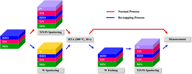
Figure 1. Fabrication process of the normal and the re-capped TiN/HZO/TiN capacitors.
Download figure:
Standard image High-resolution imageFor the crystal structure analysis of the MIM capacitors, grazing incidence x-ray diffraction (GIXRD) was used. High-resolution transmission electron microscopy (HRTEM) and energy dispersive spectroscopy (EDS) were used for structural and elemental analyses, respectively. The polarization–electric (P–E) field measurements were carried out using a precision LC II (Radiant Technologies) at a frequency of 1 kHz. Leakage current and capacitance–electric (C–E) field were measured using a Keysight B1500A semiconductor device parameter analyzer. The C–E measurement was executed with an amplitude of 50 mV at a frequency of 10 kHz. All measurements were performed at RT.
Results and discussion
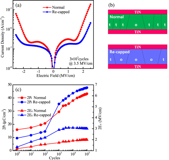
The polarization versus electric field curves are shown in figure 2(a), measured after 3 × 10³ cycles. Square and triangle pulses were used for the field cycling and reading, respectively. The amplitude and frequency of both pulses were 3.5 MV cm−1 and 1 kHz, respectively. These results show that the 2Pr value of the re-capped TiN/HZO/TiN capacitor is approximately 40 μC cm−2, which is approximately 6 μC cm−2 higher than that of the normal capacitor. Moreover, the coercive field of the re-capped capacitor increased by approximately 65% compared to that of the normal capacitor. Therefore, a squarer-shaped hysteresis loop is achieved by the re-capping process.

Figure 2. (a) Polarization–electric field hysteresis loops and (b) 2Pr and 2Ec as a function of the electric field of TiN/HZO/TiN capacitors.
Download figure:
Standard image High-resolution imageThe P–E hysteresis loop of the re-capped capacitor shows an undisputed polarity asymmetry of coercive field. The positive coercive field (∣Ec +∣) is 2 MV cm−1, which is almost twice compared to the negative one. The appropriate description for this phenomenon is the non-equivalent bottom and top interfaces. During the ALD process for growing the HZO film and the RTA process for crystallization, the bottom electrode was partially oxidized, resulting in more oxygen vacancies at the bottom interface [47]. We summarized the 2Pr and 2Ec values measured at different electric fields in figure 2(b).
To investigate the cause of the Pr increase in the re-capped capacitor, GIXRD scanning was performed on different samples (figure 3(a)). In general, the monoclinic (−111), orthorhombic (111), tetragonal (011), and monoclinic (111) peaks of Hf0.5Zr0.5O2 film are located at 28.54°, 30.4°, 30.8°, and 31.64°, respectively [48]. The GIXRD results show a significant left-shift of the o (111)/t (011) characteristic peaks in the re-capped capacitor compared to the normal capacitor, which indicates an increase of the o-phase in the Hf0.5Zr0.5O2 film. It is generally known that the high fraction of the non-centrosymmetric o-phase is the reason for the high Pr [1, 4]. A W capping electrode with a relatively low TEC [37] can induce a large in-plane tensile strain during the cooling step of the RTA process

where  and
and  are the TEC of the film and capping materials, respectively, and T
A
is the annealing temperature. Considering constant TECs for W (4.5 × 10⁻⁶ K−1), TiN (7.0 × 10⁻⁶ K−1) [37] and HZO (9.0 × 10⁻⁶ K−1) [49] at the range of 25 °C–500 °C, our calculations showed that the stain level applied to the HZO film during the cooling process is approximately 0.09% when we used TiN as a capping electrode and approximately 0.21% for the W capping electrode. The higher level of in-plane strain increases the formation of o-phase which is accompanied by a left-shift of the Bragg peaks in the XRD patterns.
are the TEC of the film and capping materials, respectively, and T
A
is the annealing temperature. Considering constant TECs for W (4.5 × 10⁻⁶ K−1), TiN (7.0 × 10⁻⁶ K−1) [37] and HZO (9.0 × 10⁻⁶ K−1) [49] at the range of 25 °C–500 °C, our calculations showed that the stain level applied to the HZO film during the cooling process is approximately 0.09% when we used TiN as a capping electrode and approximately 0.21% for the W capping electrode. The higher level of in-plane strain increases the formation of o-phase which is accompanied by a left-shift of the Bragg peaks in the XRD patterns.
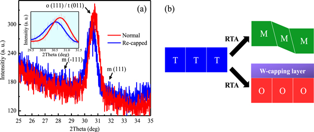
Figure 3. (a) GIXRD patterns of normal and re-capped TiN/HZO/TiN capacitors. (b) Schematic illustration of the phase transition from t- to m- or o-phases. The W-capping electrode suppresses the twin deformations, which are responsible for the m-phase formation.
Download figure:
Standard image High-resolution imageThe in-plane tensile strain results in the suppression of the m-phase by preventing twin deformation and enables the t- to o-phase transformation (figure 3(b)) [27].
The results of the HRTEM and EDS analysis are shown in figure 4. For an accurate comparison, Ti Kα lines of TiN/HZO/TiN capacitors are separately compared in figure 4(d), which obviously shows a lower intensity at the top interface of the re-capped capacitor. This reveals a considerable suppression of TiOx formation in the interfacial region between the HZO and the TiN top electrode. In case of the normal capacitor, the top interface has undergone an annealing procedure at the elevated temperatures (500 °C). Therefore, the formation of an interfacial layer is possible. On the other hand, the re-capped capacitor was not subjected to any further heat treatment after deposition of the TiN top electrode, which was carried out at RT; thus, the suppression of TiOx was expected.

Figure 4. (a) Cross-sectional HRTEM and EDS map analysis results for the re-capped TiN/HZO/TiN capacitor. Cross-sectional HRTEM images and EDS line analysis of the (b) normal TiN/HZO/TiN capacitor and (c) re-capped TiN/HZO/TiN capacitor. (d) A comparison of Ti Kα lines of TiN/HZO/TiN capacitors.
Download figure:
Standard image High-resolution imageUsing TiN as a capping electrode causes the formation of an interfacial TiOx layer during the thermal process, because the reaction of Ti with oxygen is considerably high at the HZO/TiN interface, especially at the elevated temperatures. Fillot et al [50] investigated the stability of different metals in connection with HfO2; according to their calculation, the Gibbs free energy of 2Ti + HfO2 → Hf + 2TiO is approximately 43 kJ mol−1 at 500 °C, which indicates the energetically possible formation of titanium oxides at the interface.
According to the theoretical simple Landau formula, Ec can be written as [51]

where Ps is the spontaneous polarization,  is the dielectric constant (more precisely, the contribution to the dielectric constant from ferroelectricity; the total dielectric constant of the medium
  =
=  +
+  contains contributions from the background polarizability
  and the ferroelectric polarizability
  ) along the direction of spontaneous polarization, and
  is the permittivity of free space. Therefore, in order to elucidate the reason for high Ec of the re-capped capacitor, dielectric constants of two capacitors were measured. The dielectric constants were extracted from the small-signal C–E measurement. The dielectric constants of the re-capped and normal capacitors at −2.5 MV cm−1 are 21 and 30, respectively (figure 5(a)). Therefore, the dielectric constant of the normal capacitor is approximately 1.5 times higher than that of the re-capped capacitor. From equation (2), considering almost the same Ps for both samples (figure 2(a)), one expects a substantial increase of Ec in the re-capped capacitor. Our measurement shows that the Ec (normal) is lower than that of the re-capped capacitor by a factor of 1.5, which agrees closely with the Landau model.

Figure 5. (a) Dielectric constant versus electric field of the normal and re-capped TiN/HZO/TiN capacitors. (b) Schematic diagram of the formation of TiOx at the TiN/HZO interface, which causes the creation of oxygen vacancies in the HZO layer during RTA.
Download figure:
Standard image High-resolution imageTwo possible mechanisms can cause the relatively low dielectric constant in the re-capped capacitor. The first is the higher o- to t-phase fraction, which was confirmed by the GIXRD results, considering that the dielectric constant of the o-phase is relatively smaller than that of the t-phase [48]. The second cause is the inhibition of TiOx formation at the interface between the HZO film and the TiN top electrode. The dielectric constant of TiO2 is large, approximately 60 [52, 53]. Using surface EDS analysis, we confirmed that the W electrode was completely removed at the interface after the RIE process (data not shown).
The reliability of the re-capping process was evaluated by measuring the current density and endurance of both types of capacitor. As shown in figure 6(a), the current density of the re-capped capacitor decreases compared to that of the normal capacitor. At −2.5 MV cm−1, the current density decreased by approximately one order of magnitude. The leakage current reduction might be due to the suppression of TiOx at the interface of the HZO/TiN top electrode [53]. Furthermore, the band gap of the HZO film may be reduced near the TiO2 [54]. The formation of TiOx oxide at the interface of the normal capacitor, which might pull oxygen from the HZO layer [44, 45], could be the cause of the high leakage current in the normal capacitor (figure 5(b)). It is believed that the accumulation of oxygen vacancies during the application of an electric field can substantially increase the leakage current in HZO-based thin films. On the other hand, the existence of the t-phase (confirmed by the GIXRD results) introduces more grain boundaries, which are accompanied by a more defective structure. It is generally accepted that the grain boundaries are one of the main paths for leakage current through HZO thin layers (figure 6(b)) [46].
Figure 6. (a) Leakage current density for different capacitor types. (b) Schematic of the tetragonal phase formation in the normal capacitor, which causes an increase in the density of the grain boundaries serving as the leakage path for electric current. (c) 2Pr and 2Ec as a function of cycle number for different capacitors.
Download figure:
Standard image High-resolution image
The accelerated endurance measurement is presented in figure 6(c). The measurement conditions are same as in figure 2(a). The endurance measurement demonstrates that the number of endurable cycles of the re-capped capacitor was comparable to that of the normal capacitor. After 103 cycles, the 2Pr and 2Ec values of both capacitors abruptly increased, which phenomenon is caused by 'wake-up effects' [55, 56].
Interestingly, the re-capped capacitor has a high field cycling effect. We assume one of the main reasons for a large wake-up effect in the re-capped capacitor is the possible formation of surface point defects (mainly oxygen vacancies) during removal of W layer using a RIE process. These oxygen vacancies can introduce built-in bias electric field which can pin domains against movement [57]. It is believed that the domain switching is controlled by the nucleation of the bulges that is free of trapping defects. This nucleation starts from interfaces. Therefore, the surface vacancies might decelerate the switching process [58]. Another reason is an insufficient electric field for polarization saturation of the re-capped capacitor in the pristine state. The less intermixed interfacial layer between the HZO film and the TiN top electrode was confirmed in figure 4(d), which might result in a high resistance state at the interface. Therefore, a high voltage drop across the top interface reduces the applied electric field to the HZO film.
Conclusion
In this paper, we propose a new method to improve the ferroelectric features in TiN/HZO/TiN capacitors. By using W capping material, an in-plane tensile strain is induced on the HZO layer, which causes the total suppression of the m-phase and an increase in the ferroelectric phase. Consequently, after removal of the W metal and deposition of the TiN top electrode, the Pr and Ec values increase compared to those of the normal TiN/HZO/TiN capacitor. In addition, the current density is reduced by one order of magnitude in the re-capped capacitor, which is attributed to the suppression of the TiOx phase, as confirmed by the EDS results. There are two significant features in the re-capping technique: strain engineering of the HZO film by using various electrode materials according to their TEC values, and interface engineering between the HZO film and the electrode. This study offers a promising approach to improving the ferroelectric features of HfO2-based devices, regardless of the type of electrode material.
Acknowledgments
This work was supported by a grant from the National Research Foundation of Korea (NRF) funded by the Korean government (grant no. NRF2018R1A3B1052693).