

Abstract
Pomegranate-like C@TiO2 mesoporous honeycomb spheres have been synthesized through two simple steps: formation of TiO2 mesoporous honeycomb spheres and the coating of polypyrrole followed by carbonization. TiO2 mesoporous honeycomb spheres are of large specific surface area of 153 m2 g−1 and contain abundant mesopores, which leads to high electrochemical activity and good kinetic performance of TiO2. A layer of amorphous carbon shell with the thickness of 30–40 nm tightly encapsulates a TiO2 mesoporous honeycomb sphere, forming a novel pomegranate-like small sphere, which significantly improves electronic conductivity and structural stability of TiO2. Benefiting from the unique pomegranate-like structure, C@TiO2 mesoporous honeycomb spheres exhibit high specific capacity, stable long-term cycling performance and good rate capability as an anode material for lithium ion batteries (LIBs). After 500 cycles at 1 C, the discharge capacity still reaches 184 mAh g−1. The electrochemical performance is superior to pure TiO2 mesoporous honeycomb spheres and most of the reported high-performance TiO2-based composites. This work provides a new high-performance TiO2-carbon-based composite material for LIBs as well as a new valuable research strategy.
Export citation and abstract BibTeX RIS
1. Introduction
The rapid development of portable electronic devices and electronic vehicles has driven an ever-increasing demand for high-performance lithium ion batteries (LIBs) [1–4]. Due to the low theoretical capacity and slow rate capability of commercial graphite, it is urgent to develop advanced anode materials to replace the traditional graphite. Transition metal oxides (TMOs) have attracted great attention as potential alternative anode materials due to their high theoretical capacity [5–9]. Among them, TiO2 has been considered as one of the most promising anode materials for its merits, such as low cost, natural abundance, non-toxicity and certain stability [10–13]. Particularly, the high working potential of 1.7 V vs Li/Li+ can avoid the decomposition of electrolyte and the formation of SEI film, improving the safety of LIBs. Nevertheless, several intrinsic drawbacks, e.g. low electronic conductivity, sluggish Li+ diffusion and poor rate capability, severely limit its practical application in LIBs [14–16].
To improve lithium storage performance of TiO2, many strategies have been proposed. Designing nanostructured TiO2 materials, for example, nanotubes [17], nanoparticles [18], nanowires [19], etc, can shorten the diffusion path of Li+ ions and the change kinetics of Li+ ions insertion into TiO2 more favorably, resulting in the increase in reversible capacity of TiO2 [20, 21]. However, pure nanomaterials readily aggregate, which severely weakens the aforesaid nanometer effect. Hybridizing nano TiO2 and various high-conductive materials, such as carbonaceous materials, can solve the self-aggregation issue of TiO2 nanomaterials, meanwhile effectively increase electronic conductivity of TiO2 [22–24]. Accordingly, this hybridization strategy has become very popular. For instance, Zhang et al composited TiO2 nanowires on reduced graphene oxide host with long cycle stability up to 5000 cycles and high rate performance of 221 mAh g−1 at a current density of 5 A g−1 [25]. We synthesized ultrafine TiO2 nanocrystalline on N-doped amorphous hollow carbon spheres with a discharge capacity of 242 mAh g−1 at 1 C after 200 cycles [26]. It is found that decreasing the particle size of TiO2 to a sufficient small range and uniformly dispersing them on high-conductive materials can remarkably increase reversible capacity and rate capability of TiO2, but very low mass loading of TiO2 is an underlying defect [27–29]. Constructing TiO2 nanosized building units to hierarchical porous microsized assemblies is a novel and effective strategy. Not only does the mass loading of TiO2 increase, but also the various positive effects induced by nanostructures can be completely released and utilized. Cai et al synthesized walnut-like porous core/shell TiO2 with super lithium storage properties [30]. Our group developed a PVP-boiling process to assemble TiO2 nanoparticles (P25) into a foam-like, 3D mesoporous structure with an average discharge capacity of 227 mAh g−1 over 200 cycles at 1 C [31]. So far, the novel hierarchical porous microsized assemblies of TiO2 are highly desirable, but there are still few materials of this type reported. This kind of assembling structure exhibits outstanding lithium storage performance, and deep investigation on them is very necessary [2–6, 13, 23].
Herein, we present a facile method to construct a unique pomegranate-like C@TiO2 mesoporous honeycomb sphere (denoted as C@TiO2 MHS) by chemical bath deposition and hydrothermal reaction followed by the coating of polypyrrole (PPy) and carbonization. The composite spheres of TiO2 and hexadecylamine (HDA) first form by chemical bath deposition and then are further developed to mesoporous honeycomb spheres as pomegranate seeds by hydrothermal reaction. PPy-derived amorphous C shell as the pericarp of the pomegranate encapsulate TiO2 mesoporous honeycomb sphere to improve conductivity and stability of TiO2. When used as anode material for LIBs, as expected, the pomegranate-like C@TiO2 MHSs exhibited outstanding cycling stability and good rate capability. At a current density of 1 C (1 C = 170 mA g−1), a reversible capacity of 184 mAh g−1 was still delivered after 500 cycles. Even at a high current rate of 20 C, a reversible capacity of 60 mAh g−1 was still obtained. These sufficiently demonstrate the structural superiority and great application potential of pomegranate-like C@TiO2 MHSs as an anode material for LIBs.
2. Experimental
2.1. Material synthesis
1-HDA and pyrrole monomer were purchased from MACKLIN. Titanium isopropoxide (TIP, 99%) and sodium dodecyl sulfate (SDS) came from Aladdin. Ethanol and ammonia solution (37–40 wt%) were supplied by Hangzhou Gaojing. Formaldehyde solution were purchased from Shanghai Lingfeng. Iron (III) chloride hexahydrate (FeCl3 6H2O) were supplied by Sinopharm Chemical Reagent. All chemicals were of analytical grade and used as received.
In this expriment, 0.1 g HDA was first ultrasonically dissolved in 10 ml ethanol, followed by the addition of 0.2 ml NH3 H2O under magnetic stirring. Then 0.1 ml TIP was dropwise added to the solution under vigorously stirring. After 15 min, the product was centrifuged, washed several times with ethanol and dried at 100 °C overnight. 25 mg the product was again uniformly dispersed in 20 ml ethanol and 10 ml H2O. The mixture was sealed in a Teflon-lined stainless-steel autoclave (50 ml in capacity) and heated at 160 °C for 18 h. The products of TiO2 MHSs were centrifuged, washed several times with water, and dried at 100 °C overnight.
6 mg SDS were dissolved in 50 ml deionized water. Then 30 mg TiO2 MHSs were added to the solution and stirred for 24 h. The solution was cooled to 0 °C through a cycled ice bath. 60 ul pyrrole monomers were slowly added to the solution under stirring in an ice bath. 480 mg oxidant FeCl3 · 6H2O was dissolved in 5 ml deionized water and then was added to initiate the polymerization of pyrrole. After polymerization reaction for 6 h, the products were collected by centrifugation, washed several times, dried at 80 °C overnight and denoted as PPy@TiO2 MHSs. They were calcined at 400 °C for 2 h with a heating rate of 2 °C min−1 in a flow of argon gas. The resulting product was the pomegranate-like C@TiO2 MHSs.
2.2. Materials characterization
The morphologies of the products were observed by a field-emission scanning electron microscope (FESEM; vltra55) and a transmission electron microscope (TEM; JEOL, JEM-2100). The crystal structure and phase of the products were characterized by x-ray powder diffractometry (XRD) using an ARLXTRA x-ray diffractometer with Cu kα radiation (λ = 1.54056 Å). Raman spectra were recorded via a DXR Raman microscope (Thermo Scientific Corporation, USA) with a laser wavelength of 532 nm. The thermo gravimetric analysis (TGA, GA-Q50) was performed in air from room temperature to 800 °C at a ramping rate of 10 °C min−1. Nitrogen adsorption and desorption isotherm measurements were performed at 77 K on a Micromeritics ASAP2010 instrument. The Brunauer–Emmett–Teller (BET) and Barrett–Joyner–Halenda (BJH) methods were used to calculate specific surface area and pore size distribution.
2.3. Electrochemical measurements
The working electrodes were prepared by a slurry process. The synthesized active material, polyvinylidene fluoride (PVDF) and acetylene carbon black were uniformly mixed in N-methyl-2-pyrrolidinone with mass ratio of 8:1:1. The obtained slurry was pasted onto pure Cu foils and dried under vacuum at 100 °C overnight. The mass loading in every electrode was around 1.0 mg cm−2. Li sheets and Celgard 2500 were used as the counter/reference electrode and the separator. The electrolyte was 1 M LiPF6 dissolved in a mixture of ethylene carbonate (EC) and dimethyl carbonate (DMC) (1:1 in volume). CR2025 coin-type half-cells were assembled in an Ar-filled glovebox. Cyclic voltammetry (CV) measurements were conducted at a scan rate of 0.2 mV s−1 on an electrochemical workstation (PARSTAT 2273). The galvanostatic discharge-charge measurements were performed within the potential window of 1.0–3.0 V (vs Li/Li+) on a battery testing system (Neware) at room temperature. Electrochemical impedance spectroscopy (EIS) was measured on PARSTAT 2273 over the frequency range from 100 kHz to 0.1 Hz with an AC amplitude of 5 mV.
3. Results and discussion
The synthesis process of pomegranate-like C@TiO2 MHSs is schematically illustrated in figure 1. HDA is a crucial material for the formation of TiO2 MHSs. On the one hand, HDA and hydrous titania (hydrolysis product of TIP) together form an organic-inorganic composite sphere through a hydrogen-bonding interaction. On the other hand, HDA acts as a pore-forming additive. It can be completely removed through the hydrothermal reaction. Meanwhile hydrous titania is also crystallized. Thus, TiO2 MHSs are obtained. TiO2 MHSs are further coated by a layer of PPy and then carbonized, forming a novel pomegranate-like structure. It retains high specific surface area of TiO2 MHSs; meanwhile significantly improves electronic conductivity and structure stability of TiO2 MHSs.

Figure 1. Schematic illustration for the synthetic procedure of C@TiO2 MHSs.
Download figure:
Standard image High-resolution imageFigure 2(a) shows the SEM image of the organic-inorganic composite spheres of HDA and hydrous titania. They are of uniform shape and size, smooth surface as well as obvious monodisperse features. The TEM image (figure 2(b)) clearly exhibits their fine structure, presenting a homogeneous solid sphere structure. It is difficult to distinguish HDA and hydrous titania inside these spheres. After the hydrothermal reaction, the solid spheres transform to MHSs with a very rough surface (figure 2(c)). In the surface of these small spheres exist the abundant pores. The hydrothermal crystallization and the removal of HDA do not induce the collapse of these MHSs. The TEM image (figure 2(d)) and high-magnification TEM image (figure 2(e)) distinctly reveal that these MHSs are in fact composed of numerous uniform nanocrystalline TiO2 with the diameter of about 10 nm. Among these nanocrystalline TiO2, abundant mesopores exist. Clearly, these mesopores are throughout the interior and surface of these small spheres. The HRTEM image (figure 2(f)) displays a distinct crystal lattice with an interplanar spacing of 0.352 nm, well coinciding with (101) crystal planes of the anatase TiO2, confirming good crystallinity of TiO2. The phase analysis on the products after the hydrothermal treatment was conducted by XRD (figure 2(g)). The XRD pattern shows well-defined diffraction peaks. All of them can be well assigned to the anatase phase TiO2 (JCPDS NO 04-0477). The short and widened diffraction peaks suggest the small size of TiO2 crystalline. The calculation based on the Scherrer equation indicates the crystal size of TiO2 is around 10 nm, which is in accordance with the TEM result. No other diffraction peaks corresponding to HDA and no other materials were detected, demonstrating the hydrothermal reaction totally removed the pore-forming agent of HDA. The microstructure of TiO2 MHSs was further examined by N2 adsorption/desorption isotherms measurement (figure 2(h)). The isotherms can be classified as a typical type-IV curve with an obvious hysteresis loop in the high-relative pressure region (0.68–0.89), demonstrating the presence of the mesopores. The BET specific surface area reaches 153 m2 g−1. The high specific surface area can offer more active sites for electrochemical reaction, improving reaction kinetics of TiO2. The pore size distribution curve calculated by the BJH method further confirms the existence of the mesopores. The main pore size ranges from 3 to 24 nm, centering at 13.6 nm. The total pore volume reaches 0.49 cm3 g−1. The abundant mesopores greatly facilitate penetration of electrolyte, as well as buffer expansion and shrinkage of TiO2 during the (de)lithiation process.
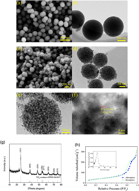
Figure 2. (a) SEM and (b) TEM images of the organic-inorganic composite sphere of HDA and hydrous titania; (c) SEM, (d) TEM, (e) high-magnification TEM and (f) HRTEM images of TiO2 MHSs; (g) XRD pattern and (h) N2 adsorption-desorption isotherms of TiO2 MHSs (the BJH pore-size distribution curve is inserted).
Download figure:
Standard image High-resolution imageAfter the coating of PPy, the independent TiO2 MHSs are assembled into clusters of grapes due to the adhesion effect of PPy (figure 3(a)). The small spheres again become smooth without burr phenomenon, and the electronic conductivity is obviously improved. This indicates PPy has successfully coated TiO2 MHSs. The TEM image (figure 3(b)) discloses that each TiO2 MHSs is coated by a layer of PPy, presenting a unique pomegranate-like internal structure. The thickness of the PPy layer is around 50 nm. After carbonization, clusters of grapes are well preserved but the electronic conductivity is further increased because the display effect of SEM is remarkably improved (figure 3(c)). The TEM image (figure 3(d)) demonstrates TiO2 nanoparticles do not grow up during the carbonization process, and TiO2 MHSs are also well retained. Nevertheless, the thickness of the carbon shell seems to decrease to 30–40 nm due to the shrinkage caused by the carbonization. The compressive pre-stress induced by this shrinkage makes the carbon shell better resist the volume expansion of TiO2 MHSs during the lithiation process, which is favorable for increasing the structure stability of TiO2 MHSs. A high-magnification TEM image (figure 3(e)) reveals the local fine structure of C@TiO2 MHSs. TiO2 nanoparticles tightly contact the carbon shell without any interspace, which can effectively improve electronic conductivity of TiO2 MHSs. The internal mesoporous honeycomb structure can be still distinguished clearly, implying the mesopores inside the TiO2 MHSs should not be filled by PPy and carbon. It is worth noting that in the carbon shell abundant micropores exist, which can allow the infiltration of the electrolyte.

Figure 3. (a) SEM and (b) TEM images of PPy@TiO2 MHSs; (c) SEM, (b) TEM and high-magnification TEM images of C@TiO2 MHSs.
Download figure:
Standard image High-resolution imageThe phase of the final product was examined by XRD (figure 4(a)). The XRD pattern only displays diffraction peaks of anatase TiO2 without any impurity. However, at 10–35°, the base line of the XRD pattern obviously rises, presenting a small hump. This means the presence of carbon materials. To further determine the structures of TiO2 and carbon in the final product, the Raman spectra was recorded (figure 4(b)). Five typical Raman peaks appear at 152, 198, 392, 501 and 628 cm−1, which well matches the Eg, Eg(2), B1g, A1g and Eg(3) characteristic peaks of anatase TiO2. At 1351 and 1577 cm−1 appear two obvious humps that correspond to the D-band and G-band of carbonaceous material. This indicates the presence of the carbon. Compared with the Raman peaks of TiO2, the intensity of the D-band and G-band are weaker, inflecting the lower content of carbon. The ID/IG ratio may be used to evaluate the graphitization degree of carbonaceous material. The high ratio value of 1.03 confirms the amorphous disordered structure of PPy-derived carbon. To obtain the content of the carbon, TGA was performed in air (figure 4(c)). C@TiO2 MHSs exhibit two distinct weight loss. The first weight loss is relatively slight, and occurs from room temperature to 200 °C, which is ascribed to the evaporation of the adsorbed moisture. It accounts for 7.5% of the total weight. The second weight loss occurs from 300 °C to 700 °C, which is attributed to the combustion of the carbon in air. After water is excluded, the content of the carbon is 56.17% and the rest is TiO2. Furthermore, EDS was also performed to further verify the constituent elements and their content (figure 4(d)). There exist four elements, C, N, Ti and O. This means the amorphous carbon should be doped by N [17]. The doping of N can greatly increase electronic conductivity of the amorphous carbon. The EDS result indicates the weight percentages of C, N and TiO2 are 53.96%, 2.70% and 43.34%, respectively, which agrees with the TGA result.
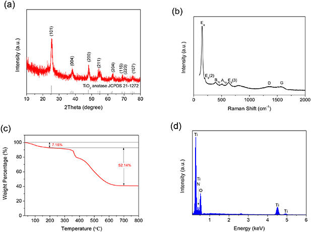
Figure 4. (a) XRD pattern; (b) Raman spectra; (C) TGA curve and (d) EDS pattern of C@TiO2 MHSs.
Download figure:
Standard image High-resolution imageThe electrochemical performances of C@TiO2 MHSs as anode material are shown in figure 5. Figure 5(a) exhibits the CV curves of C@TiO2 MHSs at a scan rate of 0.2 mV s−1 in the potential window of 1.0–3.0 V. One pair of well-defined reduction/oxidation peak appears at 1.66 and 2.08 V, corresponding to Li+ intercalation and extraction in the TiO2 lattice [32]. Except for the reduction/oxidation peak, the other region of CV curves is nearly rectangular, demonstrating a strong pseudocapacitive lithium storage behavior. Aside from the first cathodic scanning, the CV curves basically overlap each other, implying good reversibility and stability. The CV curves of C@TiO2 MHSs clearly differ from those of TiO2 MHSs (figure 5(b)). (1) The reduction/oxidation peaks of C@TiO2 MHSs are not prominent but those of TiO2 MHSs are very sharp and prominent, indicating lithium intercalation storage is not dominant for the former, but dominant for the latter. This could be due to the inhibition effect of the amorphous carbon shell that limits the rapidly entering of the electrolyte, so suppresses sufficient contact between the inner TiO2 nanocrystalline and the electrolyte. (2) The rectangular shape of C@TiO2 MHSs is more remarkable, and the corresponding area is larger. These suggest that the amorphous carbon shell can inspire the pseudocapacitive storage effect of TiO2 MHSs [27, 33–35].
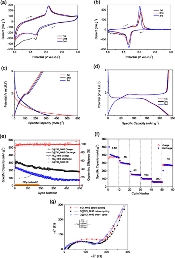
Figure 5. Cyclic voltammograms of (a) C@TiO2 MHSs and (b) TiO2 MHSs at a scan rate of 0.2 mV s−1 in the potential window of 1.0–3.0 V; the first three discharge-charge profiles of (c) C@TiO2 MHSs and (d) TiO2 MHSs at current density of 1 C; (e) cycling performances of C@TiO2 MHSs, TiO2 MHSs and PPy-derived C at 1 C; (f) rate capability of C@TiO2 MHSs; (g) Nyquist plots of C@TiO2 MHSs and TiO2 MHSs before cycling, C@TiO2 MHSs after 1 cycle (the insertion is equal circuit mode).
Download figure:
Standard image High-resolution imageFigure 5(c) shows the discharge-charge profiles of C@TiO2 MHSs in the first three cycles at a current density of 1 C (1 C = 170 mA g−1). Generally, the discharge profile of TiO2 includes three typical regions [36, 37]. The first region is a fast potential decrease from open circuit voltage to about 1.75 V, corresponding to the homogeneous Li insertion into the bulk by a solid-solution Li storage mechanism of TiO2. The potential plateau at 1.75 V is the second region which reflects Li+ insertion and occupation of interstitial octahedral sites of anatase TiO2. The third region is a potential slope from 1.75 V to 1.0 V. For C@TiO2 MHSs, their charge and discharge plateaus shrink to be a very short plateau and an inflection point, meaning the lithium intercalation reaction is suppressed. This point obviously differs from the long charge and discharge plateaus of pure TiO2 MHSs, as shown in figure 5(d), which possibly results from the enclosed environment induced by the carbon shell that limits rapid sufficient contact between TiO2 MHSs and electrolyte. However, the first and the third regions of the discharge profiles are especially remarkable, and the corresponding discharge capacity reaches 47/47 mAh g−1 and 262/282 mAh g−1 in the second and third discharge process, much higher than 11 and 95 mAh g−1 of TiO2 MHSs. This indicates the amorphous carbon shell changes the common lithium storage mechanism of TiO2 MHSs and enhances the solid-solution and pseudocapacitive Li storage effects of TiO2. These characteristics of the discharge-charge profiles agree well with those of the corresponding CV curves.
Figure 5(e) demonstrates the cycling properties of C@TiO2 MHSs at a current density of 1 C. The first discharge capacity reaches 554 mAh g−1 but the second one drops to 343 mAh g−1. The initial irreversible capacity loss is mainly due to the intercalation of Li+ ions into irreversible sites of TiO2 and irreversible decomposition of the electrolyte [1, 38]. Afterwards, the discharge capacity slowly declines, but is always much higher than the theoretical specific capacity of TiO2. At the 500th cycle, the discharge capacity still reaches 184 mAh g−1, exhibiting high electrochemical activity. The coulombic efficiencies in most cycles are higher than 99% except the initial 20 cycles, showing superior reversibility. By contrast, the discharge capacity of TiO2 MHSs is lower, and the decline rate is faster. At the 500th cycle, TiO2 MHSs only deliver a discharge capacity of 74 mAh g−1. This comparison demonstrates the amorphous carbon shell has a remarkable effect on improving reversible capacity and cycling stability of TiO2 MHSs. Figure 5(e) also provides the cycling performance of PPy-derived carbon at 1.0–3.0 V. The negligible reversible capacity (around 13 mAh g−1) of PPy-derived carbon demonstrates the discharge capacity of C@TiO2 MHSs mainly comes from TiO2. In comparison with other reported high-performance TiO2-based composites, the cycling performance of C@TiO2 MHSs exhibits a prominent advantage (table 1), highlighting the important significance of the pomegranate-like structure. Figure 5(f) displays the rate performance of C@TiO2 MHSs. At a current density of 0.5 C, C@TiO2 MHSs can deliver a discharge capacity as high as 500 to 368 mAh g−1, presenting high electrochemical activity. At 1 C, the discharge capacity stabilizes at 298 mAh g−1. At 5 C, 10 C and 20 C, the discharge capacity decreases to 150, 98 and 60 mAh g−1, presenting a certain high-rate capability. When the current returns to 1 C, the discharge capacity may reach about 273 mAh g−1, recovering to 91.6% of the initial level at 1 C. The impressive capacity retention ratio indicates C@TiO2 MHSs can withstand high-current charge-discharge reactions, meanwhile retaining the stability of the material structure.
Table 1. Cycling performance comparison between C@TiO2 MHSs and other high-performance TiO2-based composite materials.
| TiO2-based materials | Current density (mA g−1) | Specific capacity (mAh g−1)/cycle number | Ref |
|---|---|---|---|
| Mesoporous TiO2 microparticles | 170 | 148/300 | [23] |
| TiO2@HCN | 170 | 216/200 | [26] |
| Core/shell TiO2 hybrid | 170 | 151/100 | [30] |
| Mesoporous rutileTiO2/C composite nanospheres | 85 | 186/50 | [39] |
| H-TiO2/GC | 100 | 178/100 | [40] |
| Composite of porous TiO2 microsphere | 168 | 180/100 | [41] |
| TiO2–rGO | 188 | 174/200 | [42] |
| MS-TiO2–HMS | 167.5 | 237/100 | [43] |
| Hollow urchin-like anatase TiO2@C | 167.5 | 165/200 | [44] |
| TiO2@C composite spheres | 168 | 248/100 | [45] |
| TiO2–C nanocomposite | 170 | 174/200 | [46] |
| Meso-macroporous hollow TiO2 | 84 | 150/100 | [47] |
| Hollow TiO2 | 200 | 174/200 | [48] |
| Anatase TiO2 hollow microspheres | 300 | 143/100 | [49] |
| This work | 170 | 260/100 233/200 184/500 |
To gain further insight into the electrochemical reaction kinetics of C@TiO2 MHSs, EIS measurements were performed (figure 5(g)). All Nyquist plots consist of a depressed semicircle in the high-frequency region and a sloping line in the low-frequency region. They correspond to charge transfer resistance (Rct) and Li+ diffusion in the electrode material. In comparison with pure TiO2 MHSs, C@TiO2 MHSs exhibit a smaller semicircle, meaning a smaller Rct. The fitted Rct value is 184 Ω versus 197 Ω of TiO2 MHSs. This decrease in Rct results from the improvement effect of the amorphous carbon shell on electronic conductivity of TiO2 MHSs [23, 44]. After 1 cycle, the contact resistance of C@TiO2 MHSs decreases from 16.88 Ω to 3.64 Ω due to the activation effect. The Rct value slightly decreases to 172 Ω, indicating good structure stability. Furthermore, the three sloping lines are basically parallel to each other. This suggests the amorphous carbon shell and the charge-discharge reaction should not distinctly influence Li+ diffusion in the inner TiO2, demonstrating good kinetic characteristics of C@TiO2 MHSs.
To verify the structure stability of C@TiO2 MHSs during charge-discharge cycling, we disassembled a coin-type cell after 500 cycles at 1 C, and then observed the morphology and microstructure of the electrode material through SEM and TEM. It was found in the SEM image (figure 6(a)) that C@TiO2 MHSs still exhibit the initial small sphere morphology without any distinct structure decay, presenting good structural integrity. The TEM image (figure 6(b)) discloses the internal structure of these small spheres. The pomegranate-like inner structure is well-preserved. 500 cycles did not damage the mesoporous honeycomb sphere structure of TiO2. C@TiO2 MHSs present excellent structural robustness, which is very favorable for long-term cycling stability of TiO2.

Figure 6. (a) SEM and (b) TEM images of C@TiO2 MHSs at 1 C after 500 cycles.
Download figure:
Standard image High-resolution image
The outstanding electrochemical performance of C@TiO2 MHSs mainly benefits from the unique pomegranate-like structure. The mesoporous honeycomb sphere is of large specific surface area and small crystal size, which endows TiO2 with high electrochemical activity and kinetics performance. The amorphous carbon shell significantly improves the electronic conductivity of TiO2; well buffering the volume variation of TiO2 and greatly increasing the structure stability of TiO2. Although the lithium intercalation storage of TiO2 is suppressed due to the coating of the amorphous carbon shell, solid-solution and pseudocapacitive Li storage effects are remarkably increased. These factors bring about higher reversible capacity and more stable cycling performance of C@TiO2 MHSs.
4. Conclusion
In summary, C@TiO2 MHSs are successfully synthesized and show the unique pomegranate-like structure that is composed of the internal TiO2 mesoporous honeycomb sphere and the external amorphous carbon shell. The mesoporous honeycomb sphere structure provides TiO2 with high electrochemical activity and kinetic performance. The amorphous carbon shell further enhances the electronic conductivity and structure stability of TiO2, and is very crucial for electrochemical performance improvement of TiO2 MHSs. These favorable structural features lead to excellent lithium storage performance of C@TiO2 MHSs, including high reversible capacity, stable cycling performance and good rate capability. This work gains new insight into the structure design of high-performance TiO2-carbon-based composite materials.
Acknowledgments
This work was funded by State Key Lab of Silicon Materials, Zhejiang University.