

Abstract
The rotation of the helical micromachines can produce efficient motion efficiency at small-scale conditions and have the potential for multi-field applications. In this study, we propose self-scrolling schemes aiming at a flexible bilayer structure that includes the strained layer and magnetic layer. The magnetic layer is composed of magnetic nanocomposites and can respond to an external magnetic field. To cope with multistructural configurations, multipatterned manufacturing solutions of machines were investigated. Under the actuation of the rotating magnetic field, the swimming abilities of the helical machines are investigated in water and in a more viscous medium, exhibiting excellent movement abilities. For the purpose of transport capacities, the machines could be patterned with the containers, and their magnetic properties were studied to evaluate the effect of containers of different lengths on the movement performance; here, the direction of the magnetic axis and the stability of the rotational motion were investigated under different magnetization conditions. The result demonstrated that the larger radial deviation of the magnetic axis allows the machines to swim wobbly, and these instabilities can be reduced by radial magnetization.
Export citation and abstract BibTeX RIS
1. Introduction
Applications such as micromanipulations and targeted drug delivery constrained by the micro-dimensions and hard-to-reach operating regions have motivated the progress of untethered self-propelled microactuators [1, 2]. Nature provides existing design experiences in certain environments, in which the motion strategies of robotics are inspired. Many biomimetic schemes have been proposed to meet various applications [3], such as simulating fish swimming and even microbial motion [4, 5]. At low Reynolds regimes, the movement of microstructures is significantly hindered by the viscous force, which overwhelms the inertia force [6]. Inspired by the effective movement strategies of microbes, various artificial micromachines have been researched to perform nontrivial tasks [7]. A very common case is that E. coli moves by rotating the helical flagella [8], which provides ideas for the movements of small machines. In particular, on-board power is difficult to integrate owing to the small scale. Thus, the involved actuation approaches were developed, such as chemical actuation [9, 10] (e.g. chemical fuel) and physical field actuation [11, 13] (e.g. magnetic, light and ultrasound). Magnetic fields, such as in magnetic resonance imaging (MRI), have been extensively applied in clinical diagnosis with the capacity to penetrate biological tissue harmlessly [14], thus becoming an attractive method. In addition, the magnetic gradient of the MRI device or its upgraded version can be used for the navigation of interventional machines, which has promising compatibility with existing medical platforms, and diagnoses and treatments can be performed in the same system [15, 16]. To maximize movement efficiency, the choice of the movement method depends remarkably on the geometric structures. For the helical microstructures, which can convert rotational motion into translational motion characterized by robust drilling motion and manipulation performance, embracing the potential applications in viscous biological medium such as body fluids, and have attracted tremendous attentions [17]. Further, the magnetic anisotropy of the helical micromachine makes it capable to respond to an external rotating field. Several approaches for magnetic anisotropy, such as deposition of magnetic thin films and the use of magnetic composites, have been applied. Magnetic metals and alloys, such as nickel and cobalt, can be exploited for thin films, which can provide the suitable hard magnetic properties [18]. Furthermore, the introduction of magnetic powders significantly expands the manufacturing schemes and develops multifunctionalities of potential applications in various fields [19, 20]. Fe3O4 magnetic nanoparticles (NPs) are very promising biomaterials owing to their excellent magnetic properties and low cytotoxicity, and they have been used in clinical applications, such as thermotherapy and MRI contrast agents [21, 22]. Some fabrication techniques have been proposed to manufacture of extraordinary microstructures, such as photolithography[23], 3-D direct laser writing (DLW) [11, 17] and template-assisted methods [24–27].
Although nature has inspired us to design micromachines with a simple movement mechanisms such as helical structures, the conflicts between applied materials and structural designs still impose many challenges in practical applications. Although the helix seems to be relatively rigid to achieve excellent propulsion capabilities in which abundant fabrication schemes for rigid helixes have been extensively developed, the soft helixes have also been created by some means, such as the use of photosensitive hydrogel materials shaped by photolithography or DLW [28, 29]. Nevertheless, the fabrication of soft helixes is restricted by materials and manufacturing processes, in which the mechanical properties of the material are related to the excellent self-supporting and anti-distortion of the structures. Thus, the soft helixes are expected to be more flexible.
In this study, we developed soft screw-propelled micromachines constructed from biocompatible materials, and we converted multipatterned elastomer films into multistructural 3D architectures using the self-scrolling technique. Polydimethylsiloxane (PDMS) is widely applied in biomedical engineering owing to its excellent biocompatibility and mechanical properties [30], so we used it as the matrix of the structures. The presented bilayer structure contains the magnetic layer and the strained layer, serving as responding magnetic field and inducing scroll, respectively. The magnetic layer was composed of PDMS and Fe3O4 NPS, and the strain layer was composed of PDMS.
2. Methods
2.1. Device fabrication process
The substrates were prepared by spin-coating a layer of AZ4620 photoresist (Merck) on a silicon wafer (500 r, 10 s and 3000 r, 30 s) and baked at 100 °C for 60 s, served as easy peeling and sacrificial layer. The magnetic layer was prepared using the following steps. (i) The PDMS (Sylgard 184, Dow Corning) prepolymer and curing agent with a weight ratio of 10:1 and 16 wt% Fe3O4 NPs (20 nm, Macklin) were prepared. (ii) The NPs were mixed with ethanol, sonicated, and stirred for 30 min, and then the PDMS prepolymer was added, heated, and stirred until the ethanol completely evaporated. (iii) The curing agent was added after cooling and stirred for homogeneous dispersion of the NPs in the PDMS solution, followed by pumping to remove air from the mixture. (iv) The mixture was spin-coated on a substrate (1200 r, 60 s, thickness about 60 μm), and baked at 80 °C to a semi-cured state. The strained layer was prepared using the following steps. (i) The PDMS solution (weight ratio of 10:1) was spin-coated on the substrate (1500 r, 60 s, thickness about 40 μm), baked at 80 °C for 20 min for complete curing. (ii) The PDMS layer on the substrate was cut into more rectangular shape. (iii) Immerse the substrate in ethanol to dissolve the photoresist to release these PDMS films.
The fabrication process illustrated in figure 1(a) involves the manufacture of typical helical machines. The stretched PDMS layer was enforced to bond to the semi-cured magnetic layer until it is fully cured to create a robust bilayer structure. The bilayer was cut at a certain angle from the stretching direction, and the cut belt is easily peeled from the substrate due to photoresist. The peeled belt can roll up along the stretching direction to induce the helix. The helix diameter and helix angle of the helical machine can be changed by altering the stretching of the strained layer and the cutting direction of the bilayer. The stretching of the PDMS layer is shown in figure 1(b). The root region has a large lateral length change, and the middle region of interest (ROI) has a more uniform strain. Therefore, the operation was performed in the ROI region. The lateral strain versus the longitudinal strain and Poisson's ratio of the PDMS film are plotted in figure 1(c), and the lateral strain increases approximately linearly with the increase in stretching.
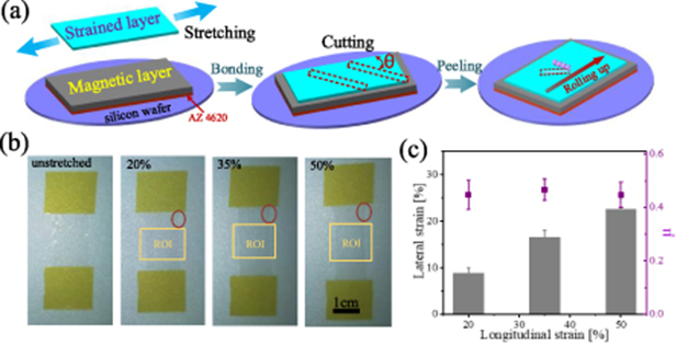
Figure 1. (a) The schematic diagram of fabrication procedure, and θ is defined as the included angle with the stretching direction. The strained layers with stretching 20%, 35% and 50%. (b) The red circle indicates the stretched root region, and the yellow rectangle indicates the ROI with a relatively uniform stretching. (c) Lateral strain and Poisson's ratio at 20%, 35% and 50% in longitudinal stretching.
Download figure:
Standard image High-resolution image2.2. Cutting angle effect
The strained layer with 20%, 35%, and 50% stretching, in the case of cutting angle θ 10°–90°, as is shown in figure 2(a). The helix angle and helix diameter are plotted in figure 2(b). The larger stretching results in a smaller helix diameter at the same cutting angle, which can be explained by the larger strain induced by stretching, leading to a smaller helix diameter. Apparently, both the helix angle and diameter decrease and then increase with the increase in the cutting angle, instead of decreasing to zero continuously. It is impractical for a material to deform in only one direction and remain unchanged in other directions, as reflected by Poisson's ratio [31]. For the PDMS layer, the longitudinal stretching will lead to a lateral contraction, so strain-induced self-scrolling occurs simultaneously in the contracted direction. The peeled cruciform in figure 3(a), with two claws roll up along the stretching direction and roll down along the contraction direction, respectively, so the direction of curling of two claws is opposite. Obviously, a flat belt cannot be obtained along any cutting angle, due to the existence of strain in any direction.
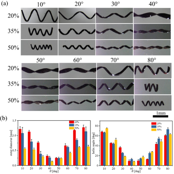
Figure 2. (a) The geometries of the fabricated helixes. The strained layers with the stretching 20%, 35%, and 50%, and the cutting angles 10°–90°, respectively. The scale bar is 1 mm. (b) The outer diameter and the helix angle versus cutting angle.
Download figure:
Standard image High-resolution image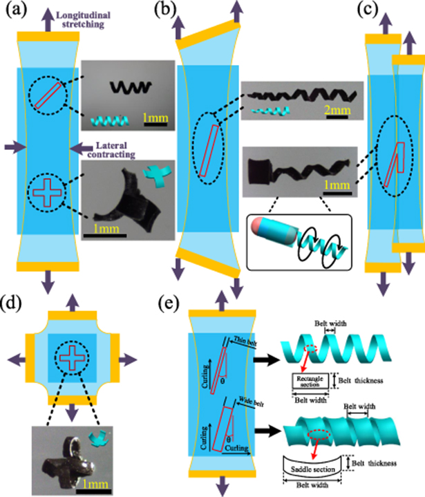
Figure 3. Multipatterned fabrication schemes. (a) The strained layer with uniform stretching create the uniform helical structures. (b) Inhomogeneous stretching lead to a conical helix, with one side stretched by 10% and the other side by 60%. (c) Two different stretches can form a sudden change in scroll parameters, with one stretched by 50% and the other one by 40%. The 50% stretching layer with 20° cutting, and the 40% with 0°. The 40%–0° pattern can be rolled into a container with a diameter larger than the helical diameter. (d) The layer is stretched simultaneously in orthogonal directions to form a stretch in all around. Typically, the peeled cruciform can be rolled up along the both stretching directions. The strained layer with the orthogonal 40% stretches. (e) The effect of thin and wide belts on the helix.
Download figure:
Standard image High-resolution imageThe direction of longitudinal and lateral strain are perpendicular, so the middle position is at 45°. The longitudinal strain dominated when the cutting angle is less than 45°, and the lateral strain dominated when it is greater than 45°, therefore, the theoretical transition angle is 45°. The helical structure near the 45° cutting (such as 40° and 50°) shows smaller helix diameter, due to the coupling effect of longitudinal and lateral strain, have no practical experimental value. Thus, combined with the fabrication result, the transition is positioned at 40°–50°. For three stretches, the transitions occur between 40° and 50°, because the ratio of stretching strain and contraction strain is approximately the same, which can be reflected in figure 1(c).
The effect of thin and wide belts on the helix, as shown in figure 3(e). If the belt is wider, the helical shape will be close to the cylindrical shape, meanwhile the curling in the non-dominant strain direction will also be obvious. For example, for a wider belt, when the helix with a cutting angle is less than 40°, the longitudinal strain dominates curling of the belt, and curling will also occur in the lateral direction, forming a saddle-shaped cross section. For a thinner belt, the cross section of helix is rectangular. In cutting process of the helix, the thinner belt is cut with a width of about 120 μm.
2.3. Mutipatterned fabrication and container integration
For a strained layer with uniform stretching, the appropriate cutting approaches can produce uniform helical machines, as shown in figure 3(a). Moreover, the non-uniform helix can be planned through the non-uniform stretching, as shown in figure 3(b). The strained layer is stretched into a trapezoidal shape, and the longitudinal strain gradually increases from left to right. The large strain corresponds to the small helix diameter, thus forming a conical helix. The strained layer with inhomogeneous stretching can induce a continuous variation in strain. However, a large strain change in a short length is difficult to obtain owing to the actual operation and material characteristics of the strained layer. To overcome this problem, the discrete strain variation can be implemented to create desirable structure pattern. Two layers with different stretches are bonded to the magnetic layer side by side and can form large strain changes at the border, as shown in figure 3(c). This feasible solution allows us to induce the desired strain result on the same bilayer. Through different cutting schemes on the two strained layers, a helical structure attached to a container can be obtained, as shown in figure 3(c). Figure 3(d) shows that the strained layer is stretched in two perpendicular directions, and the peeled cruciform, with two claws roll up along the two stretching directions. Therefore, the multi-directional stretching of the strained layer can obtain the different curling direction.
3. Experiment results and discussions
3.1. Helical machines actuated in water and glycerin-aqueous solutions
The outer layer of the helix is subject to tensile stress and the inner layer is subjected to compressive stress, as shown in figure 4(a). The existence of prestressing maintains the helical shape while allowing the bilayer to resist external forces and can improve the overall structural stiffness [32, 33]. The presented micromachines are quite soft, exhibiting a large deformation under external force and restoring the previous shape after removing the force, as shown in figure 4(a). In some delicate conditions, the soft helical machines can reduce the damage of the drilling motion to the environmental matrix. Since the smaller stretches result in larger helix diameters, and the loose helical structure is quite out of shape confined by the thickness and stiffness of the bilayer, therefore we target the more compact structures.
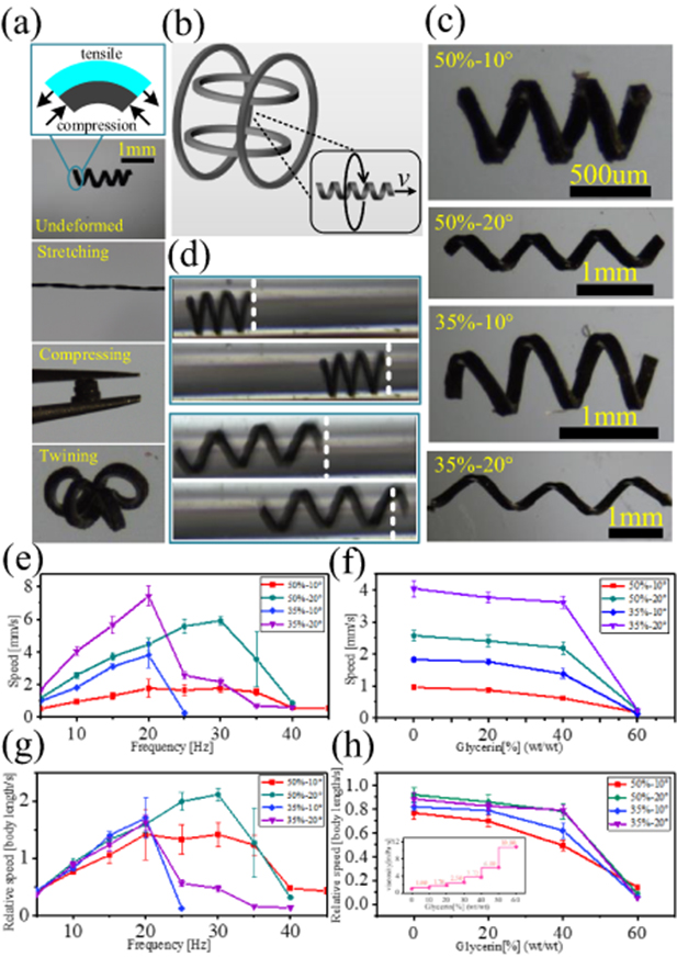
Figure 4. (a) The bilayer are subjected to tensile and compressive stress in outer layer and inner layer, respectively. Large deformabilities of the machines under external forces. (b) The schematic of swimming actuated by the rotating magnetic field generated by two pairs of Helmholtz coils. (c) The machines patterned with 50%–10°, 50%–20°, 35%–10° and 35%–20°, respectively. (d) The 50%–10° machine swims at the 10 Hz. (e), (g) The average swimming speed and relative speed of machines with respect to magnetic frequency. (f), (h) The swimming speed and relative speed of the machines under different glycerin concentrations at 10 Hz. The inset shows the relationship between glycerin concentration and viscosity at 20 °C [34]. The average speeds were obtained through five measurements.
Download figure:
Standard image High-resolution imageRotating magnetic fields are widely used in the actuation and steering of magnetic helical micromachines, exhibiting excellent operability and feasibility. The torque T exerted on the machine in a uniform field can be described as T = m × B, where m and B denote the magnetic dipole moment of the machine and the external magnetic field, respectively. Therefore, the alignment effect of the magnetic moment in a uniform field contributes to the continuous rotation of the helical machine and subsequent locomotion when applying an appropriate frequency.
The typical motion capability of these helical machines was demonstrated using a uniform rotating magnetic field with a density of 8 mT, as shown in figure 4(b). Radial magnetization was performed for the helical machines, which is discussed below. The patterns 50%–10°, 50%–20°, 35%–10°, and 35%–20° (figure 4(c)) with three turns were actuated in deionized (DI) water. Figure 4(d) shows that the machines with 50%–10° and 50%–20° swim at a magnetic frequency of 10 Hz (video S1, supporting information (available online at stacks.iop.org/JMM/30/085001/mmedia)). The variations of average swimming speed and relative speed (body length per second) versus applied frequency are plotted in figures 4(e) and (g), respectively. The maximum average speeds of 50%–10° and 50%–20° are about 1.7 mm s−1 (1.4 body length s−1) and 5.9 mm s−1 (2.1 body length s−1) at 30 Hz, respectively. The maximum average speeds of 35%–10° and 35%–20° are about 3.8 mm s−1 (1.7 body length s−1) and 7.4 mm s−1 (1.6 body length s−1) at 20 Hz, respectively. Noticeably, the speed will decrease when the frequency exceeds the so-called step-out frequency. For these torque-actuated fashions, this frustrated behavior is inevitable because the magnitude of the magnetic torque is limited.
The helical structure with larger diameter is subject to greater fluid resistance at the same rotating frequency, and the fluid resistance increases with the increasing rotating frequency. Therefore, the 35% stretching structures reach the maximum speeds at 20 Hz, and the swimming speeds decay rapidly due to the larger fluid resistances when the frequency exceeds 20 Hz. Compared with 35% stretching structures, 50% stretching structures are subject to less fluid resistances, so they reach their maximum speeds at 30 Hz, and the speeds decay slowly when the frequency exceeds 30 Hz.
The speeds of 35%–10° and 50%–10° are lower than 35%–20° and 50%–20° at certain frequencies, respectively, because the helical angle of 20° cutting is less than 10° cutting and thus has a larger helical pitch, and one rotation translates a larger distance. Nevertheless, the relative speeds of 35%–10°, 35%–20° and 50%–10°, 50%–20° are nearly equal at a certain frequency, respectively, accounted by the fact that the 20° cutting has the longer body length than that for the case of 10°.
Generally, biological fluids, such as blood, have a higher viscosity than water. Therefore, to investigate their drill abilities in higher viscous media, 20%, 40%, and 60% glycerin aqueous solutions were prepared. The swimming speed and relative speed versus glycerin concentration are plotted in figures 4(f) and (h), respectively. The speeds decrease with the increasing viscosity, with 0%–40% decreasing slowly and 40%–60% decreasing rapidly, which can be reflected from the lower viscosity of 0%–40% and the larger of 40%–60%. The solution viscosity is 10.8 mPa · s (at 20 °C, the water is about 1 mPa · s) at 60% concentration, and they exhibit low speeds due to relatively large viscous forces (about 0.17, 0.24, 0.13, and 0.25 mm s−1).
3.2. Actuation of helix-containers
The helical structures are simple moving units and can be multifunctional by integrating some of the appendixes. For this purpose, the pattern schemes were planned to endow the machines with the ability to transport cargo. The container is attached to the end of the helix, and the cutting scheme is shown in figure 3(c).
The diameter of the container is slightly larger than the helix, so that the helix can act as the bottom of the container, forming a relatively closed barrel-like structure, which can be loaded with suitable blocks without leaking. We prepared five helix-container machines using 50%–20° and 40%–0° patterns, with the containers of 0.87, 1.62, 2.22, 3.05, and 3.97 mm in length, and helixes of three turns, as shown in figure 5(a). Meanwhile, five separate containers identical to those in the helix-containers were prepared, as shown in figure 5(b).
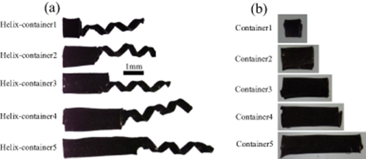
Figure 5. (a) The helixes with 3 turns patterned by 50%–20° scheme and the attached containers patterned by 40%–0° scheme. (b) The separate containers with different lengths patterned by 40%–0° scheme.
Download figure:
Standard image High-resolution imageThe container can also respond to an external magnetic field owing to its use of the same material as the helical tail, so the movement of the containers was analyzed in the rotating field. We discuss the case of non-radially magnetized containers, and the misalignment angles (the angle between the magnetization direction and the radial direction) were measured according to the alignment effect of the magnetic axis in a uniform weak magnetic field, as shown in figure 6(a). The results of magnetization show that their magnetic axes present the misalignments, which also exhibit more evident misalignment with increasing container length. When the length–diameter ratio of the container is relatively large, the axial dimension is more significant, and the easy axis will play a significant role in non-radial magnetization, so the axial offset of the magnetic axis is more remarkable. Therefore, the misalignment angle of the longer containers is close to 90°.
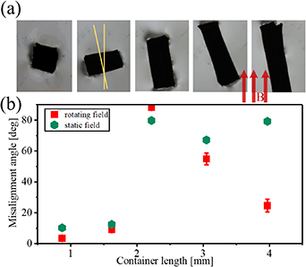
Figure 6. (a) The containers are non-radially magnetized. The misalignment angles of magnetic axes are measured by placing them in a uniform weak magnetic field B (generated by a pair of Helmholtz coils with a field intensity about 5mT). With the surface tension of water, the machines can float on the water surface, so their magnetic axes can sensitively align with the weak field. The angle between yellow lines is the misalignment angle. (b) The misalignment angles of containers are measured in the static and the rotating field, respectively.
Download figure:
Standard image High-resolution imageThe containers were actuated using a rotating magnetic field, in which the containers exhibited wobbly rotation without swimming, as shown in video S2. Clearly, the misalignment of the magnetic axis led to the wobble, and the misalignment angles of the wobbly containers were measured, and compared with the misalignment angles of the magnetic axis, as shown in figure 6(b). The misalignment angle of container5 in the rotating field is significantly smaller than the misalignment angle of its magnetic axis, and the main consideration is that the interaction between the longer container and the water hinders the amplitude of wobbling.
Figure 7(a) shows the magnetic axes of the helix-containers after non-radial magnetization, and in this case, the swimming of these machines at 10 Hz is shown in video S3 (supporting information). The video shows that the machines swim wobbly. Figure 7(b) shows the magnetic axes of these machines after radial magnetization, and the magnetic axes show less misalignment. Figure 7(c) shows that helix-container1 transports a PDMS block at 10 Hz (video S4, supporting information), with a speed of 0.68 mm s−1, which is lower than the no-load speed.
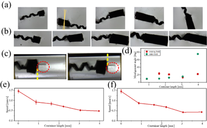
Figure 7. (a) The magnetic axes of the machines after non-radial magnetization. (b) The magnetic axes of the machines after radial magnetization. (c) The container of the machine can carry cargo. (d) The misalignment angles of the helix-containers are measured in the static and the rotating field, respectively. (e) The average speeds of helix-containers after non-radial magnetization are measured at 10 Hz. (f) The average speeds of helix-containers after radial magnetization are measured at 10 Hz.
Download figure:
Standard image High-resolution imageFigure 7(d) plots the misalignment angle of the machines, and the misalignment angle of the helix-container5 in the rotating field is significantly smaller than the misalignment angle of its magnetic axis. Here, we deal with the swimming misalignment angle at a low frequency of 10 Hz because the high-speed rotation at high frequency will contribute to restraining the wobble even if there is a large magnetic axis misalignment angle due to fluidic interactions [11].
Figures 7(e) and (f) plot the swimming speeds of non-radially and radially magnetized helix-containers, which indicate that the swimming speed decreases with increasing container length. The helix-containers are equipped with the same helixes, which means that they can provide the same power, while the containers themselves cannot provide the propulsions. So, the longer container experiences a larger fluid resistance in the swimming direction and decreases the speed. In video S3, it can be seen that although the structures show unstable swimming, but not show large wobble angles. Therefore, under the same actuating conditions, the swimming speeds of the machines are not notably increased after radial magnetization.
Noticeably, the translation of the machine is converted by the rotation movement, so the rotation performance is very important. Whether the container is magnetic or not, the increased resistance in the translational direction is inevitable, but the magnetic container can contribute to the rotation performance and overcome the rotating resistance.
The non-radial magnetization induce a non-radial magnetic axis and cannot guarantee the stability of the movement. The purpose of radial magnetization is to obtain a more stable swimming performance, and the swimming of the helix-container5 exhibits a small wobble in the presence of a longer container (video S5, supporting information).
Table 1 summarize the constituent material, fabrication method, and maximum relative speed of the magnetic helical micromachines. The magnetic property of micromachine largely determines the swimming performance. The micromachines can present strong magnetism due to the use of ferromagnetic metal, such as nickel, showing excellent swimming capabilities. For biocompatible applications, the magnetic nanomaterials, such as Fe3O4 Nps, are widely used, and the introduction of magnetic Nps can hinder the performance of photosensitive materials. Therefore, a small proportion of magnetic Nps are embedded, and result in relatively weak magnetism. Helical machines based on self-scrolling can embed more magnetic Nps, which contributes to the swimming ability.
Table 1. Comparision of helical machines in material composition and fabrication.
| Ref. | Matrix material | Magnetic material & distribution | Fabrication method | Maximum relative speed (body length s−1) |
|---|---|---|---|---|
| [28] | Hydrogel | Fe3O4 Nps & surface decoration | DLW | 0.4 |
| [29] | Hydrogel | Fe3O4 Nps & uniform embedding | Lithography & self-folding | 0.3 |
| [11] | SU8 or IP-L | Nickel & Surface deposition | DLW | 18 |
| [27] | Palladium | Nickel & Surface deposition | Template-assisted electrochemical growth | 5 |
| This paper | PDMS | Fe3O4 Nps & uniform embedding | Self-scrolling | 2 |
4. Conclusion
We utilized the self-scrolling technology based on a bilayer composed of Fe3O4 nanocomposites and elastic PDMS to fabricate soft helical micromachines. Then, we demonstrated the multiple parameters and functions of the machines through the multipatterned manufacturing schemes. The ability to scroll depend on the design of the strained layer, and we planned a uniform strain, continuously varying strain, and discretely varying strain, which derived uniform helix, conical helix, and helix with container, respectively. For typical helical machines, helix diameters and helix angles are planned by adjusting the strain and cutting angle.
We demonstrated the basic motion capabilities of helical machines in DI water and in a more viscous glycerin solution, in which the maximum average speeds of 50%–10°, 50%–20°, 35%–10°, and 35%–20° patterns in water are about 1.7, 5.9, 3.8, and 7.4 mm s−1, respectively, and the lower performances were presented at 60% glycerin solution. The machines with containers can transport cargo, and the effects of containers on the swimming performances were analyzed. The magnetization schemes determine the motion effects for this torque-actuated fashion, in which the desired magnetic axis can be obtained by adjusting the magnetization scheme owing to the magnetism of the magnetic layer. After non-radial magnetization, as the length of the container increases, the deviation of the magnetic axis from the radial direction is obvious, and the swimming wobble is more significant. Therefore, more near radial magnetic axes of the machines can be obtained after radial magnetization, and in this case, the machine with the 3.97 mm container exhibits stable swimming.
4.1. Annex
4.1.1. Magnetic properties and magnetization of the machines.
The rotation of the helical machine following a rotating field is due to the continuous alignment of its magnetic axis with the direction of the uniform magnetic field. Therefore, the anisotropy of the magnetic axis dictates the direction of the magnetic torque. Evidently, the ideal situation is that the magnetic axis is along the radial direction of the helix for better swimming performance. However, the magnetization of the machines is not desirable because their geometries are of the same order of magnitude in three dimensions and cannot be regarded as one-dimensional, such as a long cylinder with a negligible diameter. Under these conditions, the direction of the magnetic easy axis is along the long axis of the object. For these machines, the easy axes of magnetization are between axial and radial directions.
The hysteresis loop plotted in figure 8(a) indicates the magnetic properties of the magnetic layer, with small remanence (about 1.7 emu g−1) and low coercivity. The machines cannot respond in a weak rotating magnetic field, which can be explained by the weak magnetization in a weak magnetic field, and the induced magnetic torque cannot overcome the fluid resistance. Thus, the magnetization of the machines in the weak magnetic field with 8 mT can be ignored, and a stronger magnetic field is needed to magnetize the machines.
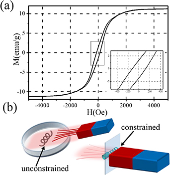
Figure 8. (a) The hysteresis loop of magnetic layer (measured by vibrating sample magnetometer, MicroSense). (b) Schematic of non-radial magnetization and radial magnetization.
Download figure:
Standard image High-resolution imageThe remanence was tested and proved to remain for a long time after magnetization, thus providing stable magnetism that can be responded in a weak magnetic field. The low coercivity allows us to easily modify the magnetic axis through simple operations, instead of using a uniform strong magnetic field. NdFeB magnets can provide a strong magnetic field (the magnet we used has a surface field intensity of about 0.2 T). Further, we used a magnet to induce the magnetization of the machines. Different induction schemes can produce magnetic axes with different directions. The magnet is close to the machines immersed in water, as illustrated in figure 8(b), and the machine is attracted toward the magnet but not close to any wall to avoid any external constraints, which induces the non-radial magnetic axis. Near radial magnetic axes can be induced by imposing some constraints illustrated in figure 8(b). In this process, the machine radially approaches and leaves the magnet to achieve radial magnetization and minimize the interference of simultaneously non-radial magnetization.
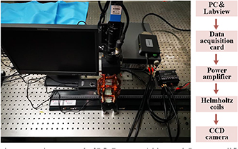
4.1.2. Magnetic actuation system.
The magnetic actuation system is shown in the figure 9, and the generated magnetic field can be controlled by the Labview Software.
Figure 9. The magnetic actuation system is composed of PC, data acquisition card, power amplifier, Helmholtz coils, and CCD camera.
Download figure:
Standard image High-resolution image
Acknowledgment
This work was supported by the Outstanding Young Talents Support Plan of Shanxi province, the Young Sanjin Scholar Distinguished Professor Plan of Shanxi Province, the Innovative Research Group Project of National Natural Science Foundation of China (Grant No.51821003) and the Shanxi "1331 project" keys subjects Construction.