

Abstract
The microfluidic technology for function microsphere synthesis has high control precision. However, the throughput is too low for industrial scale-up applications. Current scale-up design focuses on a multi-channel in 2D, in which the distribution uniformity parameter δ increases linearly, resulting in the deterioration of the flow distribution performance. The 3D modular scale-up strategy could greatly alleviate this problem, but no design principles have been developed yet. For the first time, this paper establishes the microfluidic 3D scale-up design criteria. Based on the modular design concept, the design method of 2D and 3D throughput scale-up parameters N and M, distribution uniformity parameters δ and β, and microchannel design parameter KR were proposed. The equivalent resistance coefficient was defined, and the influence of different parameters on a 2D array and 3D stack was analyzed. Furthermore, the error correction method was studied. It was found that the two-stage scale-up process contradicted each other. A good scale-up performance of one stage led to the limitation of another stage. Increasing the resistance of each channel Ru could both increase the two-stage scale-up performance, which was an important factor. A single-module scale-up system with 8 channels in a single array and 10 arrays in a vertical stack, which had 80 channels in total, was designed and fabricated based on the proposed design criteria for generating Chitosan/TiO2 composite microspheres. The average particle size was 539.65 µm and CV value was about 3.59%. The throughput was 480 ml h−1, which effectively increased the throughput scale and the product quality.
Export citation and abstract BibTeX RIS
1. Intruduction
Microfluidics, which has undergone rapid development in recent years can be applied in various fields such as chemistry, biology, medicine, etc [1]. It is acknowledged as controlling fluids accurately on the microscale [2]. Compared with the traditional techniques, microfluidic technology can be used to synthesise microdroplets with uniform size and controllable structure [3–7]. Microdroplets of different structures and materials have a wide range of applications in many fields [8–11].
Despite the obvious benefits, most research is confined to the laboratory scale, and focus on exploring the new microfluidic chips with a different structure to have a better control of size, component and material of microparticles. However, they ignore the low throughput and other practical obstacles which are related to the applications in industrial production. Fortunately, many researchers and companies have carried out relevant studies in an attempt to solve the difficulties brought about by the large-scale industrialization, such as the benefits, microchannel structure and production rate [12].
For the challenge of low production rate, the general method is to use multiple channels in parallel arrangement [13]. The appropriate structure can keep the flow in each branch as uniform as possible [14], which is the basis for the scale-up strategy. Many large-scale droplet generation devices of different structures have been published [15–20]. The 2D and 3D scale-up are two scale-up forms.
Two-dimensional scale-up is currently the main form, and its structure is simple. Therefore, most researchers chose to parallel a large number of channels in two dimensions for large-scale droplet generation [16, 19, 20]. When designing a scale-up structure, it is necessary to satisfy the flow distribution uniformity and fully consider the parameters matching for various design. Some researchers have proposed corresponding scale-up design criteria based on the 2D ladder-like network of microchannels and applied it to the design of microfluidic double emulsion devices. They connected 15 channels in parallel, and the droplet throughput reach 1 kg d−1. The coefficient of variation is less than 6% [21]. Later, some researchers also applied it on a 3 cm × 3 cm PDMS microfluidic chip to integrate 512 drop makers with the particle size of about 86.1 µm [22] and integrated up to 1000 flow focusing generators with production rate of 1.5 l h−1 [23].
However, a large number of microchannels in parallel in two dimensions will also bring some hidden trouble. The 2D and 3D scale-up effects have been compared. The 2D scale-up uniformity parameter δ is proportional to the number of channels N. The increased N leads to the increased δ which reflects the deterioration of the flow distribution performance. With the same number of channels, the 3D scale-up stacking process makes much less increasement of uniformity parameter δ or β than it in two dimensions, which can effectively limit the deterioration of distribution performance [24].
Therefore, 3D scale-up has advantages over two dimensions for the same throughput. At present, there are some 3D structures for high-throughput generation. A stackable microfluidic droplet generator consisting of 512 droplet makers on 4 layers with a particle size of about 200 µm has been published [15]. There has also been a modular scale-up, in which 16 parallel droplet makers are arranged in a single module. And it used the integration of multiple modules to amplify with the production rate of 50 g h−1 [17].
On the other hand, the parameters that need to be considered in the 3D structure are more complicated than the 2D ones. The matching of different scale-up parameters leads to the various product quality. Some researchers have realized this problem. They studied the effects of different scale-up parameter proportioning on the final distribution performance from 2D to multi-dimensional scale-up and the effects of different dimension on distribution performance under the same throughput [25]. In spite of this, no 3D scale-up design criterion have been proposed, from which the specific suggestions for parameter selection can be made based on actual requirements and conditions to obtain optimal results.
In response to the above problems, we proposed a set of new design criteria for 3D scale-up in this paper. Combining ideas from 2D arrays, 3D stacks to the modular integration [24], the design principle was presented. At the same time, various parameters involved in 3D scale-up were studied, and the influence of various parameters was analyzed to provide guidance for the optimization of scale-up performance. Based on the proposed design criteria, a microfluidic droplet generation module with 80 channels was designed and optimized. The monodispersity of the prepared Chitosan/TiO2 composite microspheres was excellent, which verified the effectiveness and reliability of the proposed design criteria.
2. Methods
2.1. Flow resistance model
The flow resistance model in a single module was used for analysis, including the flow resistance among neighboring channel inlets (Rf), the resistance of each channel (Ru), the equivalent resistance of a single array (Rc), the flow resistance of vertical channels among neighboring arrays (Rν), and the motivation in a fluid gravitational field (Rg), as shown in figure 1. In order to achieve uniform flow distribution in the 3D microfluidic system, Ru should be significantly greater than Rf while Rc should be also much greater than  . Based on the above rules, it is possible to derive the influencing parameters and the modular scale-up design criteria.
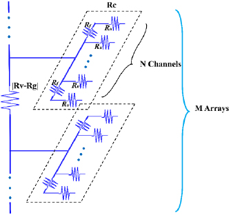
Figure 1. Model for the hydraulic resistance of a 3D microfluidic network.
Download figure:
Standard image High-resolution image2.2. Equivalent resistance of a single array
The Rc is an important parameter which is a bridge that connects 2D parallel array and 3D modular scale-up. Mathematical and physical methods can be used to calculate Rc.
The design criteria of the 2D arrays in ladder geometry have been proposed and demonstrated for the uniform flow distribution [21–23]:

In order to reveal the intrinsic relationship among scale-up influencing parameters, flow uniformity and microchannel structure, the above design criterion was also modified based on the ladder-like distribution. The two parameters δ and β were used to characterize the flow distribution performance. The smaller values of these two parameters are, the more excellent the flow distribution performance is, and the more uniform the particle size is. The equation (1) can be modified as equations (2) and (3) for the 2D array and 3D stack. N is the number of channels in the array and M is the number of arrays in the stack.
The coefficient k was used instead of δ/N, and the Rf can be derived from equation (4):
The mathematical formula was used to describe the 2D resistance model in figure 1, as shown in equation (5), where Rc,N and Rc,N−1 was the equivalent resistances of N channels and N − 1 channels.
Solve the above general formula, and finally get mathematic relationship for Rc,N, as shown in equation (6):
where  .
.
![$\xi =\left[ \frac{k}{2}+(\frac{{{f}^{N}}\left(k \right)+1}{{{f}^{N}}\left(k \right)-1})\frac{\sqrt{{{k}^{2}}+4k}}{2} \right]=f(\frac{\delta }{N},N)$](https://content.cld.iop.org/journals/0960-1317/28/10/105021/revision2/jmmaad746ieqn003.gif) is the equivalent resistance coefficient of the array, then equation (6) can be simplified as shown in equation (7):
is the equivalent resistance coefficient of the array, then equation (6) can be simplified as shown in equation (7):
The calculation of the flow resistance R, is analogous to the basic principle of the circuit, since the flow of the fluid in the channel is similar to the transfer of the current in the wire. According to the ohmic formula R = U/I, the single channel resistance can be get as shown in equation (8), where Rchannel is the flow resistance of the channel, dP is the pressure drop between the inlet and outlet, and Q is the flow rate of the channel.
Ri is the resistance of a circular channel under laminar flow which is determined by channel diameter, length and fluid viscosity. We can use equation (9) to estimate it:
3. Results and discussion
3.1. Relationship between equivalent resistance efficient and 2D array
It is found that Rc,N is related to ξ and Ru from the definition of equivalent resistance in the 2D array. Either of these two parameters increase will lead to the increment of Rc,N. The equivalent resistance coefficient ξ, which is an integrated function of N and δ/N, is related to 2D parallelization number N and the parameter of flow distribution performance δ. δ is mainly affected by the structure of the distribution, such as the parallel array or the circular array. Since ξ is a complex physical parameter, it needs to be discussed in detail. The relationship among ξ, N and δ in the 2D array is studied.
N directly affects the production rate. The higher N indicates the higher production rate. δ directly affects the uniformity of distribution. The smaller δ results in the higher uniformity. Therefore, in the 2D array, it is necessary to obtain a higher value of N and a smaller value of δ. To further study their internal relationship, we have got figure 2(created by Matlab) which is the curve family of ξ changing with δ/N and N. In the figure, the X-axis is δ/N while the Y-axis is ξ. For example, if we parallelize 8 channels in 2D array, N will be 8 and a purple curve will be selected. Different δ are selected to obtain different ξ. As can be seen from the figure, when N is small, the correlation among ξ, δ and N is obvious. Higher δ indicates the higher ξ. But increasing N will lead to a smaller ξ. With the increase of N, the curve tends to be gentle, and the influence of δ on ξ becomes lower, mainly depending on the value of N. When N equals 64 or more, these curves basically coincide and achieve convergent. Then ξ converges to 0.0733, and it has the lowest correlation with δ and N.
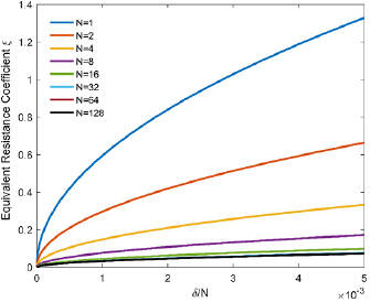
Figure 2. The equivalent resistance coefficient ξ with different N and δ/N.
Download figure:
Standard image High-resolution imageTherefore, in the 2D array, if the value of N is high enough, the ξ is the minimum and the curve is gentle, regardless of N and the δ; if the value of N is limited, N and δ should be considered to determine ξ, and then calculate the value of equivalent resistance.
3.2. Relationship between equivalent resistance efficient and 3D stack
Substitute equation (3) of design criterion in 3D stack into the equation (7) of equivalent resistance. Equation (10) can be obtained:
Similar to N and δ of 2D array, M is the number of vertically stacked arrays. It directly affects the droplet throughput. The higher M will lead to the higher throughput. β is an indicator of vertical flow distribution performance. The smaller β value results in higher uniform distribution. Therefore, in the 3D stack, it is also necessary to obtain a higher value of M and a smaller value of β.
Equation (10) can be modified as equation (11), where  is defined as the design parameter of the stack/module. KR means the ratio of the resistance of vertical flow distribution channel to the resistance of single channel, which is the core in designing the single channels and the vertical flow distribution channels. The smaller KR leads to the more conservative channel design. On the other word, it is much easier to obtain the higher throughput and better uniformity.
Equation (11) reveals the relationship between ξ and the 3D stack. Figure 3 is the curve family of ξ changing with β/M and KR(created by Matlab). It can be seen from the figure that, for the determined KR, the smaller the ξ leads to the higher β/M. The smaller KR, which results in the more conservative design, leads to the smaller β/M with the same ξ. Therefore, to obtain the same value of β, the number of stacked array M can be increased appropriately. When the value of KR is conservative enough to be below 5 × 10⁻⁵, several curves are basically coincided. Therefore, it is not necessary to get further conservative design. A higher level of processing difficulty is related to the more conservative design. When KR and ξ is constant, for a fixed β/M value, the higher uniformity means that we should decrease β as well as M, or we can decrease the uniformity(β increases) to get a higher M.
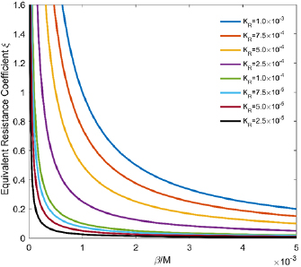
Figure 3. The equivalent resistance coefficient ξ with different KR and β/M.
Download figure:
Standard image High-resolution imageEquivalent resistance is an important parameter that relates 2D array and 3D stack, and ξ can also reflect the performance of two-stage scale-up. From the perspective of ξ, in the 2D array, it is desirable to increase N and lower δ to achieve higher output and better uniformity, but the result is to achieve a small ξ. When the ξ is small, the fixed KR in the 3D stack will result in a higher β/M. It is actually detrimental because we need to get a smaller β/M to accommodate the higher throughput with the higher M and the higher uniformity with the smaller β. It can be seen that the requirements of two-stage scale-up for ξ are in conflict. According to equations (2) and (3), it can also be seen that increasing Ru can get smaller δ and β at the same time, which is good for two-stage scale-up. However, the improvement of Ru means the increased difficulty of mechanical processing and the channel structure design. In practice, combined with the mechanical processing and design conditions, we can determine Ru as much as possible. And then according to the parameter N, ξ can be determined from figure 2. β/M can be determined by certain KR and ξ in figure 3. The values of β and M should be properly assigned.
3.3. Multi-stage module design criteria
The multi-stage module design criterion equation (12) can be got by combining equation (7) with (11):
In this criterion, there are three categories of parameters, which are the throughput scale-up parameters M and N, the distribution uniformity parameters δ and β, and the microchannel design parameter KR. The two throughput scale-up parameters are directly related to the whole throughput. Higher M and N lead to higher throughput. The two distribution uniformity parameters characterize the distribution performance of 3D multi-stage scale-up module. The smaller two values are, the more uniform the distribution performance is. And the microchannel design parameter is related to the machining geometric parameters. The smaller value indicates the more conservative design, but it will be subject to processing accuracy, space volume and other factors. We discussed these parameters separately based on the derived multi-stage module design criterion. Since δ and β have the same meaning, for convenience, we made these two values equal.
The relationship between throughput scale-up parameters and microchannel design parameters was discussed. Better uniformity can be achieved while setting the two uniformity parameters δ and β to 0.005. Figure 4 shows the curve family of M changing with different N and KR while δ and β are fixed at 0.005(created by Matlab). For different KR (KR is respectively 2.5 × 10⁻⁵, 5 × 10⁻⁵, 7.5 × 10⁻⁵, 1 × 10⁻⁴, 2.5 × 10⁻⁴, 5 × 10⁻⁴, 7.5 × 10⁻⁴, 1 × 10⁻³.), the selected value of M, N is different. The higher KR indicates that the curve is closer to the coordinate axes, and the values of M and N will be selected more strictly. Conversely, smaller KR indicates the more conservative design, so throughput scale-up parameters may be appropriate to increase. For either case, the maximum of M can be determined from the figure 4 after selecting parameter N. Or according to the demand for throughput scale-up parameters, KR can be determined by the graph, and then it is used to guide the microchannel design. It can also be found from the figure that when increasing Ru, considering that δ and β are fixed values, N and M will be further improved as KR decreases.
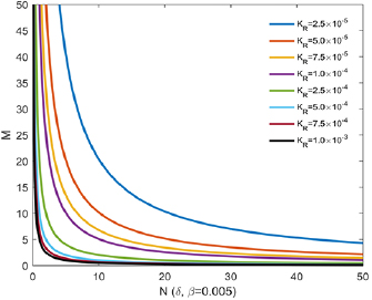
Figure 4. 3D throughput scale-up parameters M with different N and KR (δ and β are fixed at 0.005).
Download figure:
Standard image High-resolution imageOn the other hand, the relationship between throughput scale-up parameters and uniformity parameters was discussed. As shown in figure 5 (created by Matlab), KR is set to be 2.5 × 10⁻⁴. For different uniformity requirements, the values of M and N are also different. Figure 5 is the curve family of M changing with different uniformity parameters while KR is fixed at 2.5 × 10⁻⁴ (Both δ and β values are 0.02, 0.015, 0.01, 0.008, 0.006, 0.004, 0.002, and 0.001). As can be seen from the figure, when KR is fixed, the higher uniformity requirements leads to a lower value of δ and β. Meanwhile, the value of M and N are selected more strictly and the increment of throughput is more limited. The appropriate increment of δ and β (flow distribution performance degradation) can greatly enhance the throughput. Based on the value of M and N, the distribution uniformity can be roughly determined.
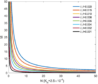
Figure 5. 3D throughput scale-up parameters M with different N, δ and β (KR is fixed at 2.5 × 10⁻⁴).
Download figure:
Standard image High-resolution imageFigure 6 is production throughput (N × M) changing with different δ, β and KR. The Y-axis is the product of 2D parallelization number N and the 3D stack number M, which is N × M. N is fixed at 8. The value of N × M is directly related to the production throughput. The dispersed phase flow rate of single unit Qcs multiplies by the total number of units N × M, and Qcs × N × M is the production throughput of a single module. For convenience, we set two distribution uniformity parameters δ = β since they have the same meaning. It can be quickly seen from figure 6 that the increment of throughput (N × M) directly leads to an increment of the values of δ and β, which refers to the deterioration of the flow distribution performance. To improve the flow distribution performance, the values of δ and β need to be reduced, and then N × M decreases. Therefore, it can be found that the demand for scale-up and the uniformity of flow distribution are in conflict. In addition, while δ and β are kept constant, smaller KR will lead to the obvious increment of N × M. The result is consistent with the discussion in section 3.2. Smaller KR reflects the improvement of Ru (resistance of each channel), which is related to the mechanical processing and the channel structure design.
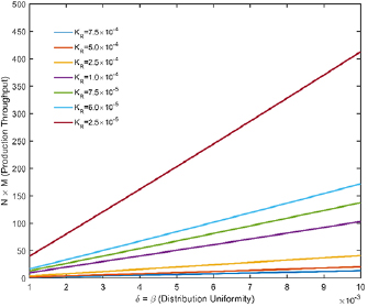
Figure 6. Production throughput (N × M) with different δ, β and KR (N is fixed at 8 and δ = β).
Download figure:
Standard image High-resolution image3.4. Correction of criteria
The above analysis was based on the ideal condition, and the flow resistance model based on ladder-shaped asymmetric structure was deduced without considering the influence of the machining error. Therefore, it is necessary to modify the above derivation process. Two basic criteria equations (2) and (3) are modified to equations (13) and (14) respectively:
where  is the error of microchannel resistance
  in machining process, which is the main influencing factor of flow distribution. Through resolving equations (13) and (15) can be obtained.
The left side of equation (15) is composed of two terms,  and
and  , respectively, revealing two key issues of fluid distribution.
  is the structural issue, which refers to the asymmetry factor of the branch structure. And it mainly reflects the pressure difference among neighboring channel inlets.
  is non-structural issue, which refers to machining process error and it is not related to the structure. To meet the uniformity of flow distribution, some conditions should be achieved:
Structural condition: the resistance among neighboring channel inlets Rf should be far less than the resistance of each channel Ru so as to ensure that the inlet pressure of each channel is nearly the same.
Non-structural conditions: the error of the resistance of each branch is negligible compared with Ru so as to ensure that each Ru is nearly the same.
Equation (14) can also be split in a similar way, as shown in equation (16):
When achieving the completely symmetrical ladder-like structure, the distribution channel evolves into a central reservoir. And the pressure of each branch is almost the same, which means reducing Rf in the maximum extent and reaching the limit of structural condition. Therefore, the distribution uniformity mainly depends on the processing error of the microchannel. In order to meet the non-structural conditions, the serpentine microchannel needs to be adopted to improve the resistance of each branch as shown in figure 7, so that the flow uniform distribution can be conveniently achieved. As the length of the serpentine channel increases, the distribution performance will also gradually increase. Our research team has presented a flow distributor based on polymethylmethacrylate (PMMA) and laser microfabrication engraving (Universal VLS2.30) [24], which uses serpentine channel [26]. Serpentine channel can balance the pressure drop at each branch inlet and the non-uniform flow resistance caused by machining process to improve flow distribution performance [27–29].
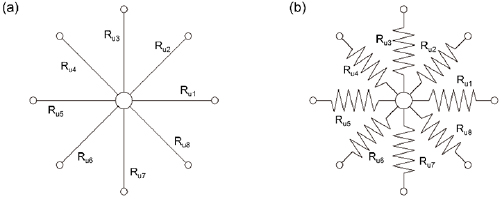
Figure 7. The completely symmetrical structure: (a) straight channel; (b) serpentine channel.
Download figure:
Standard image High-resolution image3.5. Experimental verification
According to the design criteria proposed in this paper, the design and manufacture of scale-up module have been carried out. In the discussion of the previous section, a long serpentine channel was adopted to meet the non-structural condition, and a circular array was adopted to meet the structural condition.
The experiment, taking into account the processing equipment and structure factor, selected 80 mm × 80 mm polymethylmethacrylate (PMMA) plate to array 8 channels. Therefore N = 8 was selected. It has been studied that in 2D scale-up criterion, 2δ should be less than 0.01 so that flow distribution performance is better, hence δ = 0.005 is selected [21–23]. As discussed in section 3.1 and shown in figure 2, ξ ≈ 0.13 was obtained.
The above parameters belong to 2D scale-up parameters, and then 3D scale-up parameters were discussed. Due to the limitation of PMMA plate size and processing precision, the total length of the serpentine channel was set to be approximately 280 mm, and the channel section was a small triangle with the size of 619 µm which was viewed by an optical microscope with a digital camera (OLYMPUS SZX7). Based on the actual processing size, the Ru value can be calculated, and then KR can be got. Through the above parameters calculated, it shows that β/M is a certain value by equation (11) and figure 3. From figure 1, the 3D scale-up can also be reduced to the 2D scale-up. Therefore, we set β < 0.005. When β is less than or equal to 0.005, the performance of flow distribution in the 3D scale-up is better. Figure 8 is the value of β changing with M. When M = 10 is set, β is just less than 0.005 while β is 0.005 197 with M = 11, meeting the flow distribution uniformity requirements. According to the above steps, we determined N = 8, M = 10.
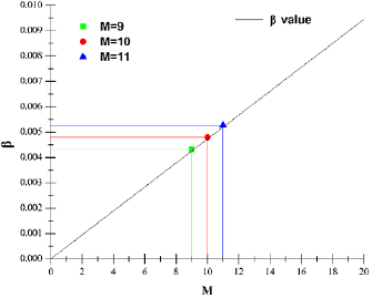
Figure 8. β changing with M (M = 9, β = 0.004 252; M = 10, β = 0.004 725; M = 11, β = 0.005 197).
Download figure:
Standard image High-resolution imageThe relevant verification experiments have been carried out by our research team. According to the design criteria, a scale-up module has been manufactured. Taking chitosan system as an example, the chitosan/TiO2 composite microspheres were prepared and the particle size, surface morphology, CV Values were also analysed. The detailed experiment has been reported by our research team [24]. The chitosan powder and TiO2 powder were dissolved in acetic acid (Shanghai Lingfeng Chemical Reagents Co., Ltd) and deionized water, forming an aqueous solution as the dispersed phase. The continuous phase was made from a mixture of paraffin liquid and petroleum ether with volume ratio of 7:5 (all from Shanghai Aladdin Bio-Chem Technology Co., LTD), and 5% span 80 was added as stabilization for chitosan droplets. The functional microspheres prepared by chitosan have good adsorption properties and they can be widely used in industrial wastewater treatment, ion adsorption and other fields [30–34].
The experiment schematic and the photograph of experimental equipment are shown in figures 9(a) and (b). The preparation process of chitosan system is shown in figure 9(c). The specific structure can refer to the patent [35]. Before the new test started, the necessary parameters could be adjusted, such as solution composition, experimental temperature and so on. The experimental parameters should be kept constant during the test. Between run to run, the variations that could be controlled were the flow rate of the dispersed phase and continuous phase. The matching of the two-phase flow determines the size of droplets. The scale-up module was run at a continuous phase flow rate Qc of 80 ml min−1 and a dispersed phase flow rate Qd of 8 ml min−1 with two-phase flow rate ratio Qc/Qd of 10. The production throughput of a single module was approximately 12 l d−1. 7.3 × 10⁵ droplets could be generated per hour in a single module. Figure 10 shows the particle size of the microspheres prepared by the module. The number on the X-axis means the 2D scale-up array from top to bottom. Due to the vertical stacking of the arrays, Qc increases while Qd decreases with the particle diameter of each array generally decreasing from the first array to the tenth array. The average diameter of chitosan microspheres is 539.65 µm and the CV value is about 3.59%.
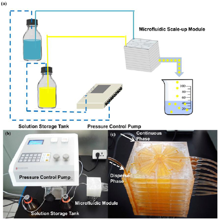
Figure 9. Scale-up module experiment: (a) experiment schematic; (b) a photograph of experimental equipment; (c) the preparation process of chitosan system.
Download figure:
Standard image High-resolution image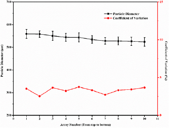
Figure 10. The particle size of the microspheres prepared by the module (the first array refers to the top one).
Download figure:
Standard image High-resolution image
Obviously, many modules can be integrated to build a microfluidic scale-up system. The flow distribution error is related to the processing error of each module and the flow rate error of fluid driving devices.
4. Conclusion
In this paper, based on the microfluidic modular design concept of a 2D array and 3D stack, we have proposed a 3D scale-up design criteria.
A flow resistance theoretical model for the pressure balance of the complicated flow network inside the microfluidic module is established. The equivalent resistance coefficient is defined and its relationship with 2D array parameters and 3D stack parameters has been analyzed. In addition, the microchannel design parameter KR is presented. According to the relationship among the channel design parameters, the throughput scale-up parameters and the distribution uniformity parameters, the design of scale-up module can be guided. It is found that the resistance of each channel Ru is a key factor affecting the uniformity of flow distribution in the process of module scale-up. Increasing Ru indicates the improvement of both two-stage scale-up effect at the same time.
The microfluidic module has been designed and manufactured by applying the design criteria, and the large-scale synthesis of monodisperse Chitosan/Titania composite microspheres is achieved. The reliability of the proposed 3D microfluidic modular design criteria has been verified and the important theoretical guidance has been provided for the design of microfluidic devices which generate high-throughput functional microsphere materials.
Acknowledgments
The research was supported by the research grant (No. 16DZ2260600) from Science and Technology Commission of Shanghai Municipality, and the Fundamental Research Funds for the Central Universities (222201717012, 222201718005).