
Abstract
This paper deals with the optimal design of monolithic piezoelectric microactuators with integrated proprioceptive sensors. Dedicated to the microrobotic and micromechatronic fields, this work details the modelling and the characterization of compliant structures with integrated actuating and sensing elements. The proposed optimal design procedure addresses not only static criteria but also dynamic ones. This leads to microdevices which are better performing with regards to mechanical (displacement, force, etc) and control (dynamics, stability, precision) characteristics. The efficient design of such devices is achieved using a flexible building block method. A topological optimization method combined with an evolutionary algorithm is used to optimize the design of a truss-like planar structure. This method chooses the best location among the different piezoelectric elements. Different mechanical, actuation or sensing elements are accordingly chosen from a data bank. From the control point of view, optimization criteria are considered, to enforce the observability of the vibrational dominant modes of the structure. Therefore, control and observation Gramians are exploited in the optimal design to shape the open-loop frequency response of both actuation and sensing functions of the integrated device. In the last part of the paper, based on these results, the optimal design and manufacture of an innovative piezoelectric flexible microgripper is proposed. The prototype is manufactured from a monolithic piezoelectric material (PIC 151). Its reduced size (15 mm × 18 mm) fits the requirements of both microrobotic and micromechatronic applications, and it is suitable for micromanipulation tasks. Closing the paper, the characterization and the performance of this integrated microactuator and the efficiency of the optimal design procedure for micromechatronic applications are shown.
Export citation and abstract BibTeX RIS
1. Introduction
In the micromanipulation and microrobotic field, microgripper devices use mainly compliant mechanisms, i.e. flexible monolithic structures undergoing elastic strain to transmit motion [1, 2]. These compliant mechanisms replace favourably jointed rigid body motions with conventional articulated mechanisms. At the small scale (e.g. in microrobotics and micromechatronics), compliant mechanisms present many advantages, including simplified manufacturing, reduced assembly costs, reduced kinematic and noise, no wear, no mechanical backlash, high precision, and ability to accommodate unconventional actuation schemes. The most interesting type of smart material used in this application is the piezoceramic PZT. Piezoelectric actuation has become widespread in micromanipulation systems where high positioning accuracy is required [3]. Beyond their appealing properties in the field of micromechatronics design, an underlying advantage of piezoelectric materials is the reversibility of their electromechanical coupling effect, which explains their potential use in microrobotic applications as actuators and/or sensors.
The design of microrobotic structures with integrated active/smart multifunctional materials is nevertheless a non-intuitive task (figure 1). The designer faces the problem of the physical integration of actuators and sensors in the compliant mechanism (i.e. the choice of the size, topology, material,...), as well as their optimal placement with regard to the performance that can be achieved by a feedback or feedforward control of the integrated device [4].
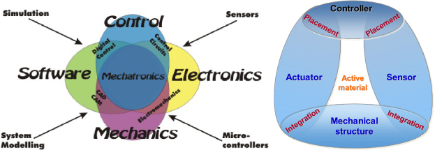
Figure 1. Mechatronics and smart structure design.
Download figure:
Standard image High-resolution imageNumerous papers address the problem of optimal placement of piezoelectric actuator and sensor parts within flexible structures. The main field of interest for engineering applications concerns the active vibration control where minimization of undesired spillover effects is required [5–7]. Most works conducted on this subject are based on controllability and observability modal analysis of the compliant structure, performed separately for the optimal placement of actuator and sensor. Another related work concerns the topology optimization which solves the problem of distributing a given amount of bulk material in a design domain subject to loading and support conditions. Design objectives, like stiffness or weight, have to be maximized or minimized. Various topology optimization methods have been applied to the design of piezoelectric devices [8, 9]. However, most of these methods consider only the optimal distribution of elastic passive materials while the locations of piezoelectric materials are already predefined. Indeed, very few studies consider the topology optimization (shape) of monolithic PZT active structures as reported in [10] or deal with the distribution of piezoelectric materials for the design of monolithic piezoelectric actuators or sensors. To our knowledge, no papers have been published previously concerning the topology optimization of monolithic piezoelectric devices that fully integrate actuation and sensing components. In addition, very few related works deal with topological optimization methods including frequency response analysis. The objective functions generally aim at the maximization of either geometrical advantage (stroke amplification), or mechanical advantage (force amplification) in the static case [11]. Even if dynamic responses are considered in some papers, it is mostly in the restrictive case of predetermined harmonic loadings. As a consequence, it should be useful to optimize all these criteria from the first design step, taking into account versatile microrobotic aspects to improve significantly the performances of such active compliant micromechanisms. A complete optimization process during the design steps would address several problems, such as avoiding noise amplification, decoupling disturbances, avoiding spillover effects and improving dynamic input/output performance which can be of great interest in the robust control-oriented design of micromechatronic devices.
In this paper, we address the optimal design of multifunctional piezoelectric compliant micromechanisms, which integrate actuation and sensing functions for microrobotics applications. Compared to existing optimization methods, our approach has the benefit of simultaneously combining the mechanical and the control design. Thus, both static and dynamic behaviours of the prototype are enhanced by the appropriate placement of the actuator and the sensing elements. Firstly the optimization tool based on a genetic algorithm is presented. This tool is specifically dedicated to compliant structures with piezoelectric materials. Based on previous works of authors taking into account the dynamic behaviour of the structure [12–14], we introduce a control-based criterion used during the optimal design process to increase the observability and the controllability of the system [15]. Such a criterion facilitates the design of a dynamic observer for position feedback control (estimation of the position based on direct piezoelectric effect). The resulting optimization method is then applied to design a fully integrated piezoelectric structure dedicated to micromanipulation purposes. Some details about the performance of the manufactured device finally close the paper.
2. A compliant mechanism stochastic design methodology
In this section, we briefly present the flexible building block method, which has been implemented for the optimal design of micromechanical planar mechanisms using a software named FlexIn (developed with Matlab). Readers can find detailed descriptions of the method in [12, 13, 16].
2.1. General approach
This optimization tool is based on a multiobjective genetic algorithm approach, which searches the optimal distribution of available building blocks. The resulting structure is thus an assembly of elementary passive, active or sensitive compliant blocks chosen in a library (figure 2). Some blocks can act as pure mechanical stiffeners, whereas others integrate actuation functions and others sensing functions. The optimization problem appoints not only topological specifications, but also an optimal set of boundary conditions (fixed frame location, contacts, end-effectors, etc), dimensions and materials, depending on some optimization criteria selected by the designer.

Figure 2. Library of compliant passive, active or sensitive piezoelectric building blocks for planar compliant mechanism synthesis using FlexIn.
Download figure:
Standard image High-resolution imageThe library of building blocks is composed of 36 building block elements, made of beam assembly. These are sufficient to build a large variety of topologies. Moreover, the block feasibility related to fabrication process constraints can also be taken into account during the problem specification. The blocks present various topologies, as shown in figure 2. Their advantage is that they can furnish multiple coupled DOFs, thus generating more complex movements with only one building block than a method which would have consisted of optimizing directly the location of the elementary beams of the truss-like structure. Thus, the function of the building block method is to save computational time during the optimization process by reducing the complexity of the problem combinatorics. It should also be noted that the calculation of the different matrices of each valued block is done once only at the beginning of the optimal design problem (before running the genetic algorithm), which saves running time.
2.2. Electromechanical FE model of the piezoelectric sensing structures
The modelling of active and sensitive piezoelectric building blocks is based on a 2D finite element method (FEM) as presented in this section.
2.2.1. FE formulation of the piezoelectric beam.
In the optimization procedure, the computation of different criteria requires the FE model of each block of the library. To obtain the FE formulation of the piezoelectric blocks, a model of a piezoelectric beam exploits direct and inverse piezoelectricity effects for sensing and actuation purposes respectively (figure 3). In the current version of FlexIn, a block is used either as sensor or as actuator but not for the two functions simultaneously. Nevertheless, it could change in future version of FlexIn.

Figure 3. Thickness-polarized piezoelectric beam transducer with electroded surfaces, and orientation in the material reference frame (e1,e2,e3). (φ1,φ2) and (q1,q2) denote respectively the electric potential for the actuation case, and the electric charges for the sensing case, of the two electrodes.
Download figure:
Standard image High-resolution imageThe matrices characterizing each block (mass, stiffness, electromechanical coupling and electric capacity) are computed at the beginning of the optimization algorithm, by the association of the corresponding beam matrices in the global coordinate system of the structure. The compliant mechanism is assumed to undergo structural planar deformation, mainly due to flexion, leading us to consider Navier–Bernoulli beam type FEs. Exploiting the transverse effect of piezoelectricity, longitudinal deformation along the L dimension is generated under the transverse electric field along the ep thickness. Using the least action Hamilton principle for electromechanical systems [17], a piezoelectric beam model is established as a set of two equations, one for the actuation mode (inverse effect) and one for the sensing mode of working (direct effect),


where  is the nodal displacement vector in the beam's coordinate system Rp = (A,xp,yp,zp) (figure 4). Mb,Kb,Gb and Cb are respectively the mass, stiffness, electromechanical coupling and electric capacitive beam matrices. Corresponding matrices are given in the appendix section. Φb = [φ1,φ2]t and qb = [q1,q2]t are respectively the vectors of electric potentials and electric charges on the upper and lower boundaries of the piezoelectric beam.
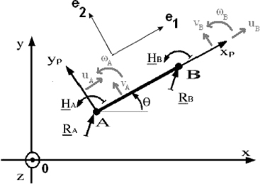
Figure 4. Curvilinear coordinates of the piezoelectric beam A–B, and its orientation in the global coordinate system R' = (0,x,y,z). R and H represent the in-plane nodal force and moment at the beam extremities.
Download figure:
Standard image High-resolution imageMatrix Gb in (1) induces piezoelectric loads, which make the actuator beam expand (or contract) proportionally to the external applied voltage φ1 − φ2. The force vector Frb, is due to external mechanical loads at the extremities of the beam  (see figure 4). The displacement field is related to the corresponding node displacement ηb by means of the shape functions, computed according to Navier–Bernoulli kinematic assumptions. The relationship (2) is used to compute the electric charges induced on the sensing beam electrodes according to the direct effect of piezoelectricity. It must be noted that experimental measurement of electric charges requires an electronic charge–voltage converter using operational amplifiers. In ideal mode, the upper and lower electrodes of the sensor piezoelectric beam are then considered short-circuited, as would be the case when they are connected to the operational amplifier. A zero-voltage difference φ1 − φ2 can therefore be assumed in the following and relationship (2) becomes
  for sensing blocks. This assumption ensures that the sensing and actuation functions of the piezoelectric beams are decoupled.
2.2.2. FE model of the FlexIn piezoelectric structures.
The mass, stiffness, electromechanical coupling and electric capacity matrices of each block are computed, considering every combination of the discrete values allowed for the structural optimization variables, i.e. the material and the size of the blocks. Each block results from the association of the corresponding beam matrices in the global coordinate system of the structure. Thus, the calculation of the different matrices of each valued block is done once only at the beginning of the optimal design problem (before running the genetic algorithm), which saves computing time.
Each flexible structure synthesized using blocks by FlexIn is defined as a finite-dimensional linear system modelled as,
The foregoing second-order differential matrix equations represent the undamped dynamic behaviour of the device. Mg and Kg are respectively the structural mass and stiffness matrices, arising from the assembly of all block matrices which constitute the general structure.
Considering the integers p,s, and r, as respectively the numbers of DOFs of the structure, number of inputs (i.e. actuators), and number of tip displacement outputs, ηg is then the p × 1 nodal displacement vector and u is the s × 1 input vector. The p × s input matrix Eg reflects the location of the actuated DOFs, while yco is the r × 1 controlled output vector representing the output tip displacement δ through the output displacement (r × p)-matrix Fg. The third equation expresses the electric charges (yob = q) obtained by the integrated sensing function from the direct piezoelectric effect. Note that Lg is the 1 × p single output matrix pointing out the placement of the piezoelectric sensor in the structure. Hence, it is important to note that there are two kinds of output: controlled output variable yco, and observed output variables yob, that are different variables. This point does not correspond to the usual case of collocated control (output is the observed variable).
3. A new performance criterion for proprioceptive observation
To successfully achieve suitable dynamic open-loop performance, an optimal topology design strategy is derived taking into account control-observability criteria. This, based on modal balanced and observability Gramians matrix interpretations, will optimally place and integrate actuators and sensors in the microstructure. The physical coordinates ηg of (3) are firstly transformed into modal coordinates z to emphasize the flexible mode contribution. Then, taking advantage of the numerical simple expressions of the Hankel singular values in modal coordinates, a new criterion is proposed to optimize the topology of the structure.
3.1. Modal representation for flexible structures
The harmonic solutions of the first equation in (3) give the eigenvector matrix Ψ and natural frequencies ωi of the system. Details of the modal representation computation can be found in [13],
where z is the p × 1 modal displacement vector, and ξi is the ith modal damping ratio introduced using Basil's hypothesis. For a p-size degree of freedom mechanical system, a 2 × p-size state vector must be defined. A typically 2p × 1 state vector x (see [18] for advantages of this choice for flexible structures), consists of modal velocities and frequency-weighted modal displacements,

Since controlled and observed output vectors are not the same, the modal state-space representation can be written as follows:
which leads to two matrices triplets (A,B,Cco) and (A,B,Cob) related to control and observation state-space models. The matrices take the forms A = diag(A1,...,Ap),  , Cco = (Cco1,...,Ccop), and Cob = (Cob1,...,Cobp), with, for i = 1,...,p,
where bi,ccoi, and cobi are the ith components of ΨtEg,FgΨ and LgΨ respectively. Matrix A is a function of the structural parameters (eigen frequencies and damping ratio), whereas matrix B depends only on the location of actuated DOF, matrix Cco on the location of desired displacement output, and matrix Cob on the location of integrated piezoelectric sensors.
3.2. Computation of the observability and balanced Gramian matrices
The observability Gramian (Wob) between state x and measured output q is found to be convenient to characterize the mode observability by the mean of the measured electric charge q. Its energetic and geometric interpretations are emphasized in [5, 19]. For stable A matrix, Wob is the algebraic solution of the following Lyapunov equation:

Assuming that the damping ratios are infinitely small and the natural frequencies well spaced, which is widely accepted for flexible structures, the block diagonal forms of the (A,Cob) couple can be exploited to give a closed-form analytical expression of the modal observability Gramian matrix [20]. The solution is then diagonal and equal to,

with, for i = 1,...,p,

where  , and I2 is the 2 × 2 identity matrix. For a given mode (ξi,ωi),γqii scalars represent the way the ith mode is seen through the piezoelectric sensor blocks.
The dominant vibrational mode contributions, which govern the dynamics of the tip deflection, have to be fully observable from the integrated sensing area of the device, in order to efficiently reconstruct and control the tip deflection. This will give the kind of transfer function sketched in figure 5: few dominant modes (high peaks) at low frequency in the transfer function between the tip position δ and the voltage input control u. Moreover, these few dominant modes have to be strongly coupled—located at the same frequencies—with the dominant modes of the transfer function between the electric charge q in the sensing areas and the voltage input control u.
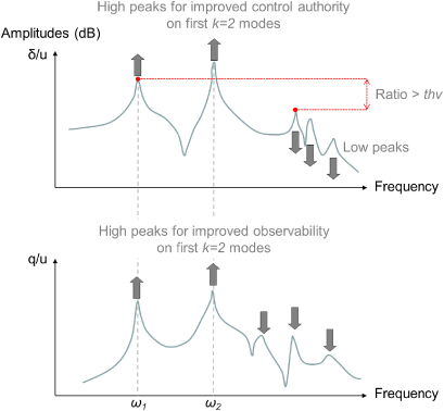
Figure 5. Example of desired control and observation transfers for good observability and controllability of the structure.
Download figure:
Standard image High-resolution imageThese dominant modes are symbolized by high Hankel singular values (HSVs), which defines the balanced Gramian matrix Weδ of the (A,B,Cco) system as follows:

where σi are the HSVs of the (A,B,Cco) system. Balanced Gramian is therefore a useful tool to quantify the joint controllability and observability of the system. When damping ratios decrease to zero, it can be shown that modal state coordinates are approximately balanced, and the approximate ith HSV for a flexible structure in this asymptotic situation is given by,
The HSV describes the degree of the corresponding modal state's input–output energy flow through the system [20].
3.3. Gramian-based criterion for the optimization of the actuator and sensor integration within a piezoelectric micromechanism
As emphasized previously, the design of active structures with both integrated actuation and sensing capabilities is non-intuitive and the designer is faced with two main issues, as follows.
- (i)A reduced model of the structure must be synthesized, which includes the few dominant low-frequency modes, without destabilizing the system by rejecting the residual modes (i.e. high roll-off after the dominant modes as sketched in figure 5). Resonance peak amplitudes must be maximized in the frequency bandwidth to increase authority control on the dominant modes of the deflection transfer. In contrast, the amplitudes of resonance peaks after cutoff frequency must be minimized to increase gain margin and to limit mode destabilization in this area (spillover phenomenon).
- (ii)If the dominant modes are not all well observed by the sensing area of the flexible structure, the reconstruction of the deflection δ will not be guaranteed in an optimal way by the observer.
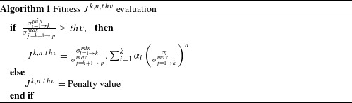
Hence, we propose a new criterion which solves these issues. Forcing the optimal structure to have k first dominant modes in the δ/u frequency response function solves the first point. Guaranteeing a high level of observability of these dominant modes by means of the electric charges q solves the second point. The algorithm 1 expresses this procedure.
Download figure:
Standard imageIn this algorithm, k is the number of the first dominant modes specified by the designer.  and
and  are respectively the level of the least dominant modes belonging to the first k modes and the level of the most dominant modes belonging to the residual modes. thv is a threshold value specified by the designer. As can be seen in figure 5, the condition
  means that the k first modes dominate by at least thv times the residual modes. The threshold value is used as a preliminary test condition in order to avoid the complex computation of the numerical criterion Jk,n,thv for each structure. A penalty value is assigned to structures that do not meet the condition requirement. These would lead to structures with poor criterion value and these will not be considered in the following generation of synthesized structures. In contrast, when the threshold inequality condition is fulfilled, the way the k first modes dominate the residual modes is emphasized through the coefficient
  in the criterion formula. The threshold value can be chosen depending on the designer requirements for his own application. From a practical point of view, this tends to increase gain margin and to limit modal spillover phenomena. Based on the authors' experience, a compromise value of threshold of about 3 is recommended. Using a higher value for thv can possibly eliminate too many candidates in the population of the genetic algorithm. This would lead to a variety of poor designs. However, in contrast, choosing too low a value of thv can lead to residual modes with high authority.
 corresponds to the coefficient of the ith observability modal Gramian Wobii and
  is a weighing ratio ∈[0,1]. When this ratio is close to 1, the corresponding ith mode is a dominant mode belonging to the first k modes. The exponent n is a tuning parameter to accelerate the convergence towards
  (to emphasize the most dominant modes). Thus, the corresponding αi is privileged compared to other mode observability. Maximizing this criterion favours flexible structures with vibrational modes where good observability of δ coincides with its dominant modes.
4. Application of the method to the design of piezoelectric mechanisms
The previous section presented a new multiobjective optimal method for the design of smart compliant structures. In this section, this method is applied to the synthesis of a monolithic micromechanism with integrated piezoelectric actuator and sensor.
4.1. Optimization problem specifications
The monolithic structure is seen as the actuator of a left-arm gripper and is supposed to be made of a single piezoelectric material PIC151 from PI PiezoCeramic Technology [21]. The structure topology is considered to have a maximal size of 15 mm × 18 mm, and a constant thickness of 200 μm. This device includes either passive, active or sensitive blocks inside a 2 × 3 mesh (see figure 6). The number of active (resp. sensitive) blocks in the structure can vary between 1 and 4. These are optimally chosen in the library displayed in figure 2. When external voltages are applied to the block electrodes, the output node (tip of the structure) has to move along the x-axis. To evaluate static mechanical criteria, the electric voltage value applied between upper and lower electrodes of active blocks is 200 V. The size ratio of the blocks can vary as bmax/bmin∈〚1;2〛 and amax/amin∈〚1;2〛 (a and b geometric parameters are displayed in figure 6). The number of blocked nodes is between 1 and 3 among the locations permitted by the problem specifications, which are reported in figure 6. The boundary conditions of possibly 1, 2 or 3 fixed nodes are exclusively devoted to the nodes that are reported in the bottom line of the mesh structure. Thus, the number and choice of the fixed nodes are considered as optimization parameters.
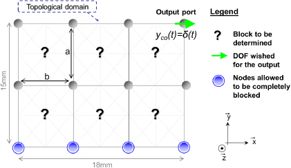
Figure 6. Mesh of the PZT compliant micromechanism with imposed and allowed boundary conditions. The a and b optimization parameters define the relative height and width of the blocks.
Download figure:
Standard image High-resolution imageFinally, three numerical criteria to be maximized with FlexIn are considered, as follows:
- J1: free mechanical displacement δx at the output node in x-direction when a constant voltage is applied to the system.
- J2: amplitude of the sensing electric charges induced on the sensing piezoelectric blocks.
- Jk,n,thv: modal observability of the mechanism output δ by the observed sensitive block charges q. In this example, we chose k = 2,n = 2 and thv = 3.
Note that J1 and J2 consider only the static behaviour of the structure, while Jk,n,thv considers its dynamic behaviour.
4.2. Results and validation
The optimization procedure was started according to the previous specifications. When the genetic algorithm does not find any new pseudo-optimum during 200 subsequent generations, the best compromises are kept and can be found on Pareto fronts. The designer can choose from among these solutions, after studying their static and dynamic behaviours. In our case, the structure chosen appears to have the best dynamic desired behaviour according to J3, while static criteria remain relatively good. This structure, displayed in figure 7, allows a tip displacement of 7 μm, and induces sensing charges around 1.9 × 10⁻⁹ C under a 200 V input voltage.
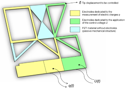
Figure 7. 3D CAD image of the left-finger microactuator integrating sensing capabilities.
Download figure:
Standard image High-resolution imageFigure 8 reports the simulated dynamic behaviour (Bode diagrams) of the δ/u control transfer function and the q/u observation transfer function. According to design specifications, these results show that maximizing the J2,2,3 criteria has led to the occurrence of two dominant resonant modes in the low-frequency spectrum of the deflection response, and these latter are perfectly observed by the electric charges.

Figure 8. Bode diagrams of the control and observation transfers of the selected structure.
Download figure:
Standard image High-resolution image5. Characterization and identification of the designed structure
In this section, we characterize the complete electromechanical model of the tip deflection of the manufactured piezoelectric device as a function of the input control voltage. The model is then identified based on experimental measurements.
5.1. Experimental setup
The microsystem prototype is clamped, and placed on x–y–z micropositioning linear stages, which are manually operated. Figure 9 shows a photograph of the experimental setup. The piezoelectric actuator requires high voltage (about ±100 V) to provide micrometric deflection. Thus, the device is supplied with a linear power amplifier (amplification ratio= 50). As seen in figure 10, the device is computer-controlled using Matlab–Simulink software and a NI Labview PXI board (sampling frequency fe = 20 kHz). Output displacement of the tip of the piezoelectric structure is directly measured along the x-axis using a 0.01 μm-resolution Keyence laser sensor.

Figure 9. Experimental setup: manufactured piezoelectric monolithic device (laser cut electroded PIC151 plate), clamping system and electrode patterns for the actuation and sensing areas.
Download figure:
Standard image High-resolution image
Figure 10. Hardware description of the computer-controlled setup.
Download figure:
Standard image High-resolution imageAn electronic charge–voltage converter is used to measure the electric charges induced in the sensing areas. The analog outputs of the laser sensor and charge amplifiers are directly wired to a 4th-order low-pass anti-aliasing filter. Corresponding double Sallen-Key electronic circuits are tuned to provide more than 75 dB attenuation at the  Shannon frequency. This permits us to filter accurately high frequency noise and high frequency unmodelled dynamics.
In ideal operating mode, the upper and lower electrodes of the sensing piezoelectric beams are considered short-circuited to respect the optimization design hypothesis. This assumption ensures that sensing piezoelectric beams are only related to the local deformation of the microactuator. The electronic signal conditioner is based on an operational amplifier in a current integrator operating mode (see figure 11). This analog conditioner for the charge measurement on the sensing electrode pattern uses a resistor Rcr in parallel to the feedback capacitance C. The role of the resistor is to discharge the capacitance C to avoid saturation effects at low frequencies. This ensures the proper functioning of the electric charge integration. The measured output voltage Vs is related to the electric charge q in s-domain as follows:
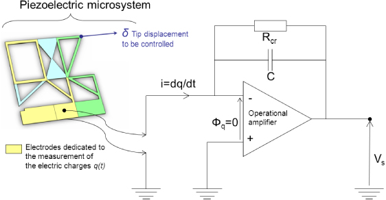
Figure 11. Electronic circuitry for the measurement of the electric charges q(t) based on a charge–voltage converter.
Download figure:
Standard image High-resolution imageMicropower precision operational amplifiers (LF412ACN, National Semiconductor Corporation) are used because they present a very low voltage drift with respect to the temperature (max. =± 0.4 μV °C−1), and a small offset voltage (max. =± 150 μV max). The performance of this model in terms of stability and accuracy and its high bandwidth (130 kHz) make it suitable as a signal conditioner. In this case, it is able to measure nC electric charges. The C feedback capacity is chosen equal to 2.2 nF, a value close to the experimental capacity of the proprioceptive sensing area of the structure. The value of the resistance Rcr = 10 MΩ must be large enough so as not to disrupt the integration function of the circuit, but not so large so as to avoid the discharge current passing through it. The choice also depends on the cutoff frequency of the system, which should stay low to avoid filtering of low frequencies.
5.2. Experimental characterization of the deflection
The vibrational dynamics are recorded experimentally by applying to the piezoactuator a low-amplitude sine input U of increasing frequency. At low amplitude and relatively high frequencies, the creep and hysteretical behaviour of PZT can be neglected [14]. Using a spectrum analyser device (HP3562A), a Bode diagram is recorded and the corresponding transfer is directly identified in Laplace domain (see figure 12). As expected by FlexIn optimization, the first two resonance modes are dominant over the following vibrational modes: this is the first point of interest in considering the criterion J2,2,3 for the design. Let us also note that the pole/zero alternate pattern is kept into this desired spectrum of interest. An identification process is thus performed considering only these first two modes in a reduced model. For identification, we consider a second-order modal transfer expansion,
This transfer function is related to the state-space model according to the following relationship:

The damping ratios ξ1 = 2.0% and ξ2 = 2.5% have been calculated from the measured quality factor at −3 dB on the Bode diagram, according to  , while values of the natural pulsations ωn1 and ωn2 are easily estimated owing to the measured resonance frequencies. Identified natural frequency values are reported in table 1.
Table 1. Experimental and theoretical natural pulsations of the D transfer function.
| Natural frequency | ωn1 (Hz) | ωn2 (Hz) |
|---|---|---|
| Theoretical FlexIn values | 2239.9 | 3800.1 |
| Experimental values | 2180.4 | 3517.3 |
| Relative errors (%) | 2.66 | 7.44 |
Static gain kc1 and kc2 are computed to respect the frequency of the first antiresonance (between the two first resonances) and the whole system static gain. This identification procedure gives,

The identified response model Gco(s) is compared with the experimental behaviour in frequency (figure 12) and time (figure 13) domains.

Figure 12. Experimental Bode diagram of the  transfer (δ in μm and U in V) and corresponding identified transfer Gco.
Download figure:
Standard image High-resolution image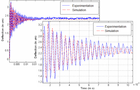
Figure 13. Experimental transient response for the  transfer (δ in μm and U in V) and corresponding identified transfer Gco.
Download figure:
Standard image High-resolution image5.3. Experimental characterization of the charge transfer
The experimental protocol used for the identification of the piezoelectric sensing dynamics behaviour is similar to the one used for the identification of the deflection dynamics: the spectrum analyser sends an excitation voltage to the actuation area of the smart structure, while the output of the electronic measurement circuit is recorded for the frequency response analysis. Measurements are reported in figure 14.
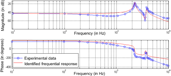
Figure 14. Experimental Bode diagram of the  transfer function (q in C and U in V) and corresponding identified transfer function Gob.
Download figure:
Standard image High-resolution imageTaking into account the criterion Jk,n,vs, the optimization design procedure of the system is effective: the modal observability by the charge transfer function Gob(s) of the first two dominant modes of the deflection transfer function Gco(s) is important (see figure 15). The roll-off at higher frequencies allows us to bring the identification of the Gob(s) transfer function to a model of order 4, with a vibrational dynamics D(s) similar to that corresponding to the actuation one,
or equivalently,

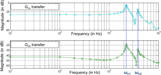
Figure 15. Correspondence of the dominant modes ωn1 and ωn2 in both deflection and charge transfer functions.
Download figure:
Standard image High-resolution imageThe computation of the static gain values ko1 and ko2 are based on the identification of the zero (antiresonance) of the experimental charge transfer function and static gain, so that,
With the same damping ratios ξ1 and ξ2 as for the deflection transfer function D(s) of Gco(s), the identified response model Gob(s) well matches the experimental response, in frequency (figure 14), and time (figure 16) domains.
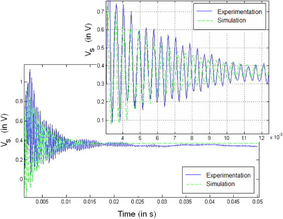
Figure 16. Experimental step response for the  transfer function (Vs in V and U in V) and corresponding identified transfer function Gob with the electronic instrumentation.
Download figure:
Standard image High-resolution imageThe reduced model can then be used with confidence owing to the optimal criterion Jk,n,thv. The proposed optimization procedure is therefore relevant to the design of compliant structures that will be easily observable and controllable in an integrated way.
6. Conclusions
A new optimal design method for integrated smart compliant micromechatronic structures has been presented in this paper. In this method, an assembly of passive, active or sensitive building PZT blocks are optimally integrated in a monolithic structure. The actuation principle exploits the inverse piezoelectric effect, while the sensing principle is based on the direct effect. Complex multiobjective design problems can therefore be solved, taking into account many versatile criteria to synthesize high performance microrobotic flexible mechanisms. In addition to classical mechanical criteria (currently encountered in topology optimization, force and displacement maximization), the proposed software FlexIn can consider simultaneously control- and observation-based criteria to integrate the actuation and sensing capabilities in the structure in an optimal way.
From the static point of view, the proprioceptive sensing areas of the flexible structure are designed to maximize the measured electric charges. This objective satisfies requirements for the good working of electronic measuring instruments. At the same time, actuation areas are placed to maximize some mechanical criteria, such as the steady-state tip deflection. From the dynamic point of view, the optimal design ensures that dominant vibrational modes related to tip deflection are fully observable from the integrated sensing parts. This ensures a good integrated tip deflection reconstruction. These static and dynamic criteria allow the design of appropriate topologies for the compliant structure. These good properties will turn out to be essential in feedback or feedforward control of the device.
Based on the proposed method, an optimal micromechanism was designed and manufactured. The characteristics of this device were experimentally measured and compared to simulations and optimal design specifications. The results confirm the good properties of the prototype and the validity of this method for the optimal design of micromechatronic actuated devices.


