Abstract
This paper introduces a new semi-flexible device able to turn thermal gradients into electricity by using a curved bimetal coupled to an electret-based converter. In fact, a two-step conversion is carried out: (i) a curved bimetal turns the thermal gradient into a mechanical oscillation that is then (ii) converted into electricity thanks to an electrostatic converter using electrets in Teflon®. The semi-flexible and low-cost design of these new energy converters pave the way to mass production over large areas of thermal energy harvesters. Raw output powers up to 13.46 μW per device were reached on a hot source at 60 °C with forced convection. Then, a DC-to-DC flyback converter has been sized to turn the energy harvesters' raw output powers into a viable supply source for an electronic circuit (DC@3 V). At the end, 10 μW of directly usable output power were reached with 3 devices, which is compatible with wireless sensor network powering applications.
Export citation and abstract BibTeX RIS
1. Introduction
Energy harvesting (EH) is a field of growing interest, with a market expected to reach some billions of dollars within few years [1]. Many principles of ambient energy harvesting have already been investigated [2] and, among them, thermal energy harvesting from thermal gradients has proved to be particularly suitable when energy harvesting from light is not possible (inside machines, under the hood of the car, etc), as well as vibration energy harvesting [2]. Like most of current small-scale energy harvesting concepts, thermal energy harvesting is aimed at supplying wireless sensor networks without batteries (or at least to recharge them), giving wireless sensor nodes a theoretically unlimited lifetime, and removing any maintenance issues such as battery replacement or recharging.
Generally, thermal energy harvesters are based on bimetallic junctions that generate a thermoelectric voltage (Seebeck effect) when submitted to a temperature gradient [3]. This concept has long been known and some thermoelectric energy harvesters have already been commercialized (MicroPelt, ThermoLife). Moreover, thermoelectric energy harvesters have quite good conversion efficiencies that may reach up to 10–15% of the Carnot cycle efficiency. Yet, they require quite expensive materials such as bismuth telluride, and developing flexible devices is rather complicated.
Here, an alternative to these standard thermoelectric devices is proposed. Thermal gradients are turned into electricity by a two-step conversion: (i) the thermal gradient is turned into a mechanical movement thanks to a curved bimetal, which is able to snap between two positions according to the temperature with a hysteresis cycle; (ii) the mechanical oscillation is then converted into electricity by using a Teflon-electret-based electrostatic converter. These new devices open the way to semi-flexible thermal energy harvesters that are compatible with mass production over large areas. After presenting the concept of bimetal-and-electret-based transducers in section 2, semi-flexible bimetal-based thermal energy harvesters are developed in section 3. Section 4 is focused on the power management circuit which is required to power an electronic device while optimizing power extraction from energy harvesters, validating the suitability of these thermal energy harvesters for wireless sensor network (WSN) powering applications.
2. Bimetal-and-electret-based converters to turn thermal gradients into electricity
Bimetals and electret-based converters have long been known, but the idea of coupling them to harvest energy from thermal gradients is new; this concept is presented and evaluated hereafter.
2.1. A bimetal-based heat engine
Bimetals are made of two strips of different metals with different coefficients of thermal expansion (CTE) which are joined together (e.g. iron and copper) (figure 1(a)). The CTE difference enables flat bimetallic strips to bend when heated up or cooled down, making bimetal transducers that convert temperature changes into mechanical movements. Curved or stamped bimetallic strips (figure 1(b)) are even smarter devices, presenting strong nonlinear behaviors, and able to snap and snap-back between two positions (sudden buckling) according to the temperature, with a hysteretic behavior, as presented in figure 1(c).

Figure 1. (a) Flat bimetals, (b) curved and stamped bimetals and (c) hysteresis cycle.
Download figure:
Standard imageThis phenomenon has been thoroughly studied by Timoshenko [4] and others [5–8], and nowadays, curved and stamped bimetals are used in many electrical and mechanical devices [4, 9, 10], such as actuators, clocks, thermometers, thermostats, circuit breakers, time-delay relays, etc.
In this paper, a curved bimetal is used as a heat engine capable of converting a thermal gradient into mechanical oscillations. The curved bimetal is clamped in a cavity with a hot source on the bottom and a cold sink on the top (figure 2). At the equilibrium temperature (e.g. T = 25 °C), the bimetal is in a convex configuration, and the metal with the higher CTE is above the metal with the lower CTE (figure 2(a)). The device is in its 'lower state' and the bimetal is in contact with the lower plate.

Figure 2. Bimetal-based heat engine (a) lower state and (b) upper state.
Download figure:
Standard imageThen, the device is placed on a hot source. The bimetal is heated up, accumulates mechanical elastic energy, suddenly snaps to its 'upper state' (figure 2(b)) and enters in contact with the upper plate (cold sink). There, it is cooled down, snaps back to its 'lower state', and a new cycle restarts.
This results in a mechanical oscillation that can be harvested thanks to a standard mechanical-to-electrical converter such as a piezoelectric, or an electromagnetic or electrostatic transducer. Actually, piezoelectric-based devices using this concept have already been proposed in [11–13].
In this paper, we focus on an electret-based electrostatic conversion to turn the bimetal's oscillations into electricity.
2.2. Electrets and electret-based converters
Electrets are electrically charged dielectrics that are able to keep their charges for years. They have long been used in microphones, sensors [14], etc and have proved their suitability in electrostatic converters as a permanent polarization source that enables a direct mechanical-to-electrical conversion without charging and discharging cycles [15, 16], greatly simplifying the power management circuit.
Electret-based converters are primarily electrostatic converters and are therefore based on a capacitive architecture made of two plates (electrode and counter-electrode), as presented in figure 3(a). The electret induces charges on electrodes and counter-electrodes to respect Gauss's law, and Qi, the charge on the electret is equal to the sum of Q1 and Q2, where Q1 is the total amount of charge on the electrode and Q2 the total amount of charge on the counter-electrode (Qi = Q1 + Q2).

Figure 3. (a) Electret-based converter, (b) equivalent electrical model with a simple load R and (c) equivalent electrical model taking parasitic capacitances Cpar into account [18].
Download figure:
Standard imageThen, a movement of the counter-electrode relative to the electret and the electrode induces a change in the capacitor geometry (e.g. the counter-electrode moves away from the electret) and leads to a reorganization of charges between the electrode and the counter-electrode through load R due to charge influence variation phenomena. This results in a current circulation through R and, therefore, the relative movement is turned into electricity.
The equivalent model of this converter is presented in figure 3(b) and has already been thoroughly discussed and validated by experimental data in [18]. As a consequence, the electret-based converter is ruled by equation (1), where Vs is the electret's surface voltage and C(t) the capacitance of the energy harvester.
Also, the instantaneous output power is expressed by (2) on a simple resistive load. It is also noteworthy that this model has been validated on more complicated loads, such as diode bridges, capacitors, and DC-to-DC converters.

The effect of parasitic capacitances Cpar (figure 3(c)) on the electret-based energy harvesters has also been discussed in [18]. Their impact on the energy harvester's output voltages and output powers has, in particular, been shown when working with high impedance loads: a decrease of output voltages, a strong decrease of maximum output voltages and, as a consequence, a decrease of output powers.
The electret-based converter is then added to the bimetal-based heat engine to turn the mechanical oscillations into electricity.
2.3. Bimetal-based thermal energy harvesters
Actually, the bimetal-based transducer can be easily coupled to the electret-based converter presented in figure 3 by adding two electret layers and two electrodes between the hot and the cold plates, as presented in figure 4. In this configuration, power is harvested both on R1 and R2, as two electret-based converters are formed: the upper electrode, the upper electret and the bimetal for the first one and the bimetal, the lower electret and the lower electrode for the second one.
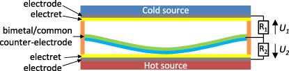
Figure 4. Bimetal-and-electret-based converter for thermal energy harvesting.
Download figure:
Standard imageThe bimetal and electret-based thermal energy harvesting concept has another great benefit: it enables the development of low-cost semi-flexible devices.
3. Semi-flexible bimetal-based thermal energy harvesters
Semi-flexible (and more generally flexible) devices are a great opportunity for thermal energy harvesting, opening the door to conformable devices, adaptable to many environments such as pipes, pumps, motors, human bodies, etc.
3.1. Designs
The semi-flexible bimetal-based devices we propose are made from two sheets of steel (75 μm) covered with a 25 μm-thick Teflon® layer. A bimetal is inserted into the cavity formed by the two sheets of steel, as presented in figure 5, and oscillates when placed on a hot source between its lower and its upper state (respectively, figures 5(a) and (b)). This movement is then harvested by the two electret-based converters.
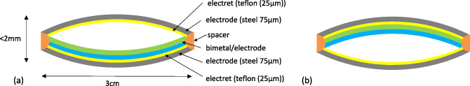
Figure 5. Semi-flexible thermal energy harvester (Teflon-based device) (a) 'lower state' and (b) 'upper state'.
Download figure:
Standard imageBesides being semi-flexible, such a design enables the development of low-cost systems made of simple and fully available materials such as Teflon or steel.
3.2. Prototypes, output voltages and output powers
The prototypes presented in this paper are made from a 115 μm-thick curved bimetal designed to snap at 47 °C and to snap-back at 42.5 °C; but obviously, other types of bimetal could be chosen, for example to work at higher temperatures. The curved bimetallic strip is made of INVAR (Fe–Ni36%), which has a very low CTE (α = 2 × 10⁻⁶), and B72M (Mn–Cu18%–Ni10%), which is the high CTE material (α = 26.4 × 10⁻⁶). The bimetal's surface is 1 cm × 3 cm and its weight is equal to m = 0.26 g; it is covered by a 1 μm-thick parylene-C layer to protect the electrets' charges during contact. The complete device size is 34 × 12 × 1.5 mm3 (0.6 cm3).
The Teflon layers are metallized on the rear face, glued on the steel electrodes, and finally charged by a standard negative corona discharge (point-grid-plane architecture) with a point voltage of 10 kV [17] for 1 h. During the first 30 min, the electret is heated at 200 °C on a hotplate. Then, the hotplate is turned off and the corona discharge is maintained while the electret and the hotplate cool down. This process enables the improvement of the charge stability of the Teflon electrets [18, 19]. Electrets are then added around the bimetal with spacers (200 μm on each side). The prototype (figure 6) is placed on a hot source at 60 °C and cooled by forced convection (fan); the upper plate's temperature is then Tcold = 36 °C. As expected, the bimetal oscillates between the two plates and the electret-based converters turn this mechanical movement into electricity. Figures 6(a) and (b) present a side view and a top view of the prototype and figures 6(c) and (d) show the two bimetal's shapes ('lower state' before the snap-through and 'upper state' after the snap-through).
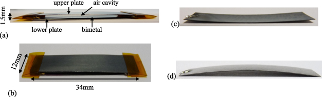
Figure 6. Prototype (a) side view (lower state) and (b) top view and bimetal's shapes (c) 'lower state' and (d) 'upper state'.
Download figure:
Standard imageThe output voltages on a 1 GΩ load for various electret surface voltages (Vs = 400 V, 450 V, 500 V) are presented in figure 7; the mean output powers on each channel (R1 and R2) are specified in the respective charts (P1 for channel 1 (R1), P2 for channel 2 (R2) and P = P1 + P2, the total mean output power of the device).
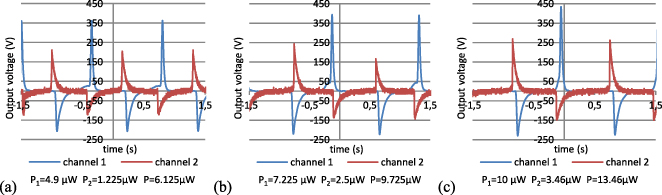
Figure 7. Output voltages and mean output powers for various electret surface voltages (a) Vs = 400 V, (b) Vs = 450 V and (c) Vs = 500 V.
Download figure:
Standard imageThe output voltages in open-circuit (1 GΩ) are large (>400 V), which is quite common in electret-based converters. As a consequence, an instantaneous output power of 200 μW can be reached thanks to these devices. However, due to the low bimetal snapping frequency (1–3 Hz), we only managed to get 13.46 μW of mean output power per device (for Vs = 500 V) on a 1 GΩ load (channel 1 + channel 2). This corresponds to a power density of 22 μW cm−3. Moreover, the snapping frequency is directly linked to the thermal gradient: the colder the upper plate, the higher the snapping frequency; and removing forced convection makes the bimetal stop. As a consequence, increasing the thermal gradient (hotter hot plate, colder heat sink) should increase the output power.
It is also noteworthy that (i) the output voltages of channel 1 are higher than the output voltages of channel 2 and (ii) the positive voltages are in both cases larger than the negative ones. The first point is due to the fact that the upper plate deforms more easily than the lower one as it is totally free to move (while the lower plate is in contact with the hotplate). Therefore, capacitances and their variations are higher in the first converter (bimetal-electret-upper plate); output voltages that are strongly linked to these two parameters are thus higher. The second point is explained by parasitic capacitances. We had already proved [18] that negative voltages are more impacted by parasitic capacitances than positive voltages; this is again confirmed here.
Finally, currently, the most important limitation of these non-optimized prototypes concerns the thermal-to-mechanical conversion, which is comprised today, for this experiment, between 0.1% and 0.5% of Carnot efficiency. Yet, we expect to increase this conversion efficiency to several per cent by optimizing the prototypes, for example by replacing air by vacuum in the cavity or by improving the bondings.
3.3. Lifetime
Lifetime is a critical point for energy harvesters, as they are made to replace batteries and, as a consequence, they should work for at least 10 years. These devices present two elements that could greatly limit the lifetime: the bimetal and the electrets. Actually, bimetals are generally sold for 10 000–100 000 cycles, which corresponds to about 14 h (in the best case) of functioning at 2 Hz; ours are qualified for more than 3 million cycles. Moreover, it is well known that contacts and elevated temperatures strongly impact the electret stability.
In order to validate the viability of this concept, two devices have been tested for 120 h (equivalent to 5 days); this corresponds to about 850 000 cycles (at 2 Hz). The electret was charged at −505 V with the process mentioned above.
At the end of these 120 h, the bimetal was still oscillating with no shift of the hysteresis cycle and the surface voltage of the electret did not drop (actually, it slightly increased to −510 V, probably due to some triboelectric effects between parylene-C and Teflon). Complementary experiments are in progress to test the devices for a longer duration, but these preliminary results are extremely encouraging.
3.4. Pros and cons versus standard thermoelectric energy harvesters
An overview of the advantages and disadvantages of bimetal-based thermal energy harvesters compared to standard thermoelectric energy harvesters is given in table 1.
Table 1. Pros and Cons versus standard thermoelectric energy harvesters.
| Advantages | Disadvantages |
|---|---|
| Low-cost | AC high voltages |
| Simple and fully available materials | Low capacitances |
| High voltages | |
| Easy to manufacture and compatible with mass production | |
| Easier to keep the thermal gradient in the structure due to the cavity (limits the thermal bridge) | |
| Flexibility/semi-flexibility |
Due to their ease of manufacture, these devices are compatible with mass production over large areas. This can be of great interest to harvest energy on large surface environments such as walls, pipes, etc. However, this requires a power management circuit that supports non-synchronous devices in parallel.
4. Energy harvesting from devices in parallel and power management circuit
As presented previously, bimetal-and-electret-based thermal energy harvesters are characterized by a high output voltage that reaches some hundreds of volts and a low output current (some 100 nA). Obviously, it is impossible to power any application or any electronic device with such a supply source, as a 3 V DC supply source is generally required. This is the reason why a power converter and an energetic buffer are needed to develop autonomous sensors; the conversion chain that turns an energy harvester into a viable supply source for an electronic circuit is presented in figure 8. The power management circuit plays an essential role in this chain and the way the power converter is controlled has a great impact on the power extracted from the energy harvester (e.g. SSHI [20]).

Figure 8. Conversion chain to develop viable energy harvesters.
Download figure:
Standard imageIn fact, many power management circuits (PMC) have been proposed in the state of the art, but they generally harvest power from only one device. Yet, power transfer on maximum output voltage has proved to be compatible with energy harvesting from multiple electret-based devices in parallel, as presented hereafter.
4.1. Power transfer on maximum voltage detection—energy harvesting from multiple devices in parallel
Electret-based output voltages are 10–100 times higher than 3 V: a step-down converter is therefore needed to fill the buffer. The most common step-down converters are the buck, the buck-boost and the flyback converters. Here, we have chosen to focus on the flyback converter, which is simple and, therefore, low consumptive to control, as only 2 controlled transistors are required.
The concept of 'power transfer on maximum voltage detection' is to send the energy from the energy harvesters to the buffer (Cb) when the output voltage of the EH reaches its maximum (figure 9(a)). The power management control circuit (PMCC), which controls the transistors, is aimed at finding the maximum voltage across the energy harvester. Then, the PMCC closes Kp to transfer the energy from the energy harvester to the magnetic circuit and closes Ks to send the energy from the magnetic circuit to the buffer Cb.

Figure 9. Power management circuit—power transfer on energy harvesters' maximum voltage (a) for one device and (b) for 2 devices in parallel.
Download figure:
Standard imageThis power management circuit is particularly suitable for one energy harvester (figure 9(a)), but can be adapted to multiple devices in parallel, as presented in figure 9(b) for 2 devices. In this configuration, power is transferred from the energy harvesters in parallel to the storage element as soon as one of the energy harvesters' output voltage reaches its maximum.
Theoretical voltages (UEH,Ucb) and currents on the primary (ip) and secondary (is) windings during the power transfer in the flyback converter are presented in figure 10. As soon as UEH reaches its maximum, Kp is closed (t = t0). The primary circuit (C,Lp) behaves like a LC circuit. Then, the energy stored into the capacitance C of the energy harvester is totally transferred to the primary inductance Lp and stored in the magnetic circuit in one quarter of a period of the Lp–C circuit, which corresponds to T1. As a consequence, UEH drops to 0 and the current ip increases up to Ipmax at t0 + T1. Ucb stays constant and equal to  (Ucb before energy transfer). T2 is a guard time, common in flyback converters. Then, Ks is closed. The secondary circuit (Ls–Cb) behaves like a LC circuit. The energy stored into the magnetic circuit is transferred to Ls and finally to Cb. Then, Ucb increases from
  to
to  . Thanks to this circuit, most of the energy stored in the capacitance of the energy harvester is transferred to the storage capacitor Cb.

Figure 10. Flyback DC-to-DC converter–theoretical voltages and currents during power conversion.
Download figure:
Standard imageThe power conversion using a flyback converter can reach 70–80% efficiency, assuming that it is well-designed; actually, the operating frequency of the flyback, the material of the magnetic core, the number of windings and the transistors, which have a major impact on the converter's efficiency, have been specifically and carefully chosen for this application. Table 2 gives an overview of the flyback's parameters that have been used to maximize the conversion efficiency.
Table 2. Flyback's parameters.
| Parameter | Value |
|---|---|
| Operating frequency | 100 kHz |
| Core material | 3F3 |
| Air gap | 0 μm |
| Windings on the primary | 320 |
| Windings on the secondary | 10 |
| Lp | 98.2 mH (experimental data) |
| Ls | 85 μH (experimental data) |
As explained previously, to control the PMC (and especially Kp and Ks), a power management control circuit (PMCC) is required. Its principle and its constitutive functions are introduced in figure 11(a): the energy harvesters' output voltage is differentiated by a RC differentiator (CD − RD), which is then compared to 0 with a MAX919 comparator, known as a low-consumption IC. These two first steps enable one to detect when the energy harvesters' output voltage reaches its maximum. Then, three delay cells, made from simple logic components (buffer, inverter, AND gate) generate the 2 control times (T1 for Kp and T3 for Ks) when the comparator switches to its 'high' state. Control times for Kp and Ks are recapitulated in figure 11(b), and here, T1 is equal to ∼5 μs, T2 to ∼1 μs and T3 to ∼10 μs.

Figure 11. Power management control circuit (PMCC) (a) functions and (b) control times for Kp and Ks.
Download figure:
Standard imageThe drawback of using a PMCC is the inherent power consumption of the electronic components that detect the maximum voltage and generate the control times. Yet, as based on low-consumption integrated circuits (simple logic components, MAX919), our PMCC consumes only 500 nA@3 V.
4.2. Experimental results on the power management circuit
The maximum voltage detection using the PMC has been validated on 3 devices. Figure 12(a) shows the output voltage UEH with three devices in parallel on a 1 GΩ load and without the power conversion step, and the maximum voltage detection (Umax) performed by the PMCC, showing the proper functioning of the circuit. This is confirmed when the power conversion step is added (figure 12(b)). But obviously, maximum voltage detection now leads to a power transfer from the energy harvesters' capacitors to the buffer capacitor Cb: UEH drops to 0 after the maximum voltage is detected. It is also noteworthy that voltage peaks of UEH are reduced when the power converter is added (figure 12(b) versus figure 12(a)). Actually, this is due to parasitic capacitances induced by the windings and the transistors. They strongly reduce the voltage peaks and, as a consequence, the output power.
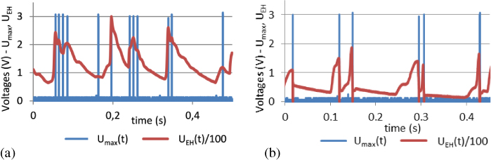
Figure 12. Maximum voltage detection for 3 devices in parallel (a) with no power conversion step and (b) with the power conversion step.
Download figure:
Standard imageThe power conversion with the flyback has also been validated (figure 13). The maximum voltage detection occurs at t = 0: Kp is closed, the energy stored into the capacitors of the energy harvesters is sent to the magnetic circuit, leading to a drop of the energy harvesters' output voltage to 0. Then, Ks is closed, and the energy stored into the magnetic circuit is transferred to Cb; is circulates on the secondary winding, reaching about 400 mA, and Ucb, the voltage across Cb, increases. The DC-to-DC power conversion reaches about 70% efficiency.
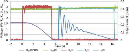
Figure 13. Current is and voltages UEH, Ucb, Kp, Ks during power conversion with the flyback DC-to-DC converter.
Download figure:
Standard imageFinally, thanks to 3 devices, placed on a hot source at 60 °C, cooled by forced convection and with Vs = 500 V (as in section 3), we managed to get about 10 μW of directly usable output power (5.45 μW cm−3): 5.6 V was stored in a 230 μF capacitor in 350 s (figure 14(a)); this has been confirmed by a voltage measurement in the steady state on a load of 1 MΩ in parallel with a 10 μF capacitor placed at the output of the magnetic circuit (figure 14(b)).
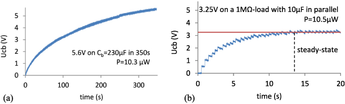
Figure 14. (a) Output voltage on a 230 μF buffer capacitor as a function of time and (b) output voltage on a 1 MΩ load in parallel with a 10 μF buffer capacitor.
Download figure:
Standard imageYet, 10 μW represents only 25% of the sum of the 3 energy harvesters' output powers (3 × 13.46 μW = 40.38 μW). In fact, this is due to the introduction of parasitic capacitances, which strongly affect electret-based energy harvesters' output powers, by:
- (i)the parallelization of the energy harvesters. Actually, the capacitance of an energy harvester is perceived as a parasitic capacitance by the other energy harvesters.
- (ii)the flyback converter, which introduces high parasitic capacitances in parallel with the energy harvesters.
However, 10 μW is compatible with a WSN powering application, providing that an intermittent running mode is adopted [17].
5. Conclusions and perspectives
We have presented semi-flexible devices able to harvest power from thermal gradients by using a two-step conversion and based on a bimetal and an electret-based converter. We managed to get a mean output power of 13.46 μW per device on a hot source at 60 °C using forced convection. A power management circuit that implements a 'power transfer on maximum voltage detection' using a flyback DC-to-DC power converter has been developed and tested on 3 devices in parallel. 10 μW of usable output power were obtained with these 3 devices, which is enough to power a wireless sensor node with an intermittent running mode.
However, the strong impact of parasitic capacitances induced by the flyback converter has been shown: research is now focused on a way to reduce them by improving windings and electronic components. Similarly, investigations are being carried out to remove the forced convection: working at higher temperatures or increasing the cavity size are two means to perform this. Moreover, limiting the conduction from the lower plate to the bimetal and to the upper plate through the bondings is also under investigation.
These new devices pave the way to low-cost thermal energy harvesters manufacturable over large areas, and especially suitable for energy harvesting on large surface environments such as walls, pipes, roofs of cars, etc. The semi-flexible property is a plus that allows one to adapt bimetal-based thermal energy harvesters to any kind of surface.
Acknowledgments
The authors would like to thank G Pitone and G Delepierre, DeltaConcept, for the design of the bimetals.
This work was partially funded by the European Regional Development Fund (FEDER/ERDF) and by the French Inter-ministerial Fund (FUI), through the HEATec project.