Abstract
A piezoelectric energy harvester is an electromechanical device that converts ambient mechanical vibration into electric power. Most existing vibration energy harvesting devices operate effectively at a single frequency only, dictated by the design of the device. This frequency must match the frequency of the host structure vibration. However, real world structural vibrations rarely have a specific constant frequency. Therefore, piezoelectric harvesters that generate usable power across a range of exciting frequencies are required to make this technology commercially viable. Currently known harvester tuning techniques have many limitations, in particular they miss the ability to work during harvester operation and most often cannot perform a precise tuning. This paper describes the design and testing of a vibration energy harvester with tunable resonance frequency, wherein the tuning is accomplished by changing the attraction force between two permanent magnets by adjusting the distance between the magnets. This tuning technique allows the natural frequency to be manipulated before and during operation of the harvester. Furthermore the paper presents a physical description of the frequency tuning effect. The experimental results achieved with a piezoelectric bimorph fit the calculated results very well. The calculation and experimental results show that using this tuning technique the natural frequency of the harvester can be varied efficiently within a wide range: in the test setup, the natural frequency of the piezoelectric bimorph could be increased by more than 70%.
Export citation and abstract BibTeX RIS
1. Introduction
Electromagnetic, electrostatic and piezoelectric transductions are the three basic vibration-to-electric energy conversion mechanisms (Williams and Yates 1996). The literature of the last few years shows that piezoelectric transduction has received most attention in powering electronic circuits; numerous scientific journals and conferences have investigated this subject intensively. The main reason why piezoelectric transducers are preferred for conversion of mechanical to electric energy is that their energy density is three times higher compared to electrostatic and electromagnetic transduction (Priya 2007).
Piezoelectric cantilever beams are widely utilized structures in energy harvesting applications because compared to other support types cantilever structures offer simplicity in construction, high flexibility and low natural frequency. Often a tip mass Mt is attached to the free end of the cantilever to reduce its natural frequency and increase its deflection. This cantilever bimorph is put on a vibrating host structure to generate an alternating voltage output for powering an electric load as shown in figure 1. There are two relevant displacements: ub is the exciting base displacement and ut is the displacement of the bimorph tip.
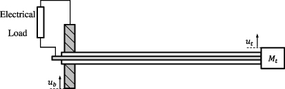
Figure 1. A typical energy harvesting system using a cantilever bimorph with tip mass.
Download figure:
Standard imageEnergy harvesting by using piezoelectric material is a promising technique, but it has some obstructions that limit the amount of generated voltage. One major limitation is due to frequency matching: the maximum power is gained when the natural frequency of the harvester matches the excitation frequency. Manufacturing tolerances, excitation frequency changes and electric load changes make frequency matching a difficult issue. Therefore, tunable harvesters are essential for this technique to be commercially viable. The mechanical power frequency sweep of a typical piezoelectric bimorph operating around its fundamental natural frequency is shown in figure 2. The normalized power describes the ratio of the instantaneous power to the maximum power and the normalized frequency describes the ratio of the instantaneous frequency to the resonance frequency. A 5% difference between excitation and natural frequency makes the harvested power drop by approximately 95%.
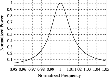
Figure 2. The mechanical power of a typical bimorph energy harvester with quality factor 35.
Download figure:
Standard image2. Tuning technique
Lesieutre and Davis (1997) investigated the dependence of piezoelectric electromechanical coupling on mechanical axial pre-compression and concluded that by applying a preload of half the buckling load to a symmetric piezoelectric bimorph device, the structural stiffness is reduced and the coupling coefficient is increased by more than 40%. Leland and Wright (2006) later used the technique of applying axial pre-compression on a simply supported piezoelectric bimorph to tune its natural frequency for an energy harvester. It was determined that a compressive axial preload can reduce the resonance frequency of the harvester by up to 24% and increase the coupling coefficient by up to 25%. Hu et al (2007) further developed this technique and proposed a special cantilever bimorph where the axial compression load can be adjusted by a tightening nut. Morris et al (2008) used the technique of applying a tensile axial load for tuning and introduced a mechanism with tunable frequency wherein the deformation of the piezoelectric elements is primarily in-plane extension, and bending effects may be neglected. A new piezoelectric harvester called an extensional mode resonator (XMR), which is formed by suspending a seismic mass with two piezoelectric sheets, was fabricated. The mechanism was made frequency tunable by an adjustable link that symmetrically pre-tensions both piezoelectric sheets. Challa et al (2008) first presented resonance frequency tuning using a magnetic force technique. They fixed two small cylindrical magnets at the free end of the cantilever, one on the top and one on the bottom, and vertically aligned two magnets above and under the first two magnets. They used magnetic repulsion for the lower side and magnetic attraction for the upper side and tuned the harvester by changing the separation distances between these magnets. In this setup, the shape of the unexcited cantilever depends on the position of the magnets and the magnetic forces are symmetric for positive and negative deflection only at a single frequency. Zhu et al (2010a) used the attraction force between two axially aligned permanent magnets to change the resonance frequency of a cantilever beam in an electromagnetic generator. The opposing faces of the relatively large magnets were curved to maintain a constant separation distance between the two magnets during operation. The resonance frequency of the system was successfully tuned between 67.6 and 98 Hz. In modelling this effect, the authors only considered axial tensile forces and their model fits well only for larger separation distances. It will be shown later in this paper that at close distances, the transverse force neglected by Zhu et al (2010a) dominates the tuning effect.
Cottone et al (2009) proposed a piezoelectric bimorph cantilever with a tip magnet used as an inverted pendulum for nonlinear energy harvesting. The magnet is repelled by another magnet with transversely adjustable position. The authors claimed that the piezoelectric harvester shows superior performance due to an additional equivalent magnetic stiffness introduced by the repulsive magnetic force. Reducing the distance between the magnets leads to an increasing effective softening until the system changes from monostable to bistable at very small distances. Stanton et al (2010) further investigated bistable nonlinear oscillators using magnetic repulsion. They proposed using a cantilever beam and analysing it analytically and experimentally.
More strategies for tuning the operating frequency of energy harvesters can be found in the review article by Zhu et al (2010b).
This paper introduces a tuning technique based on the classical piezoelectric bimorph with an additional magnet at its free end. A second magnet, opposing the first one in the axial direction, exerts additional forces on the vibrating bimorph, which depend on the distance d of the magnets, see figure 3. As d can be adjusted without touching the vibrating bimorph, the harvester natural frequency can be adjusted before and during operation. Other than in the design by Challa et al (2008), the magnetic force on the deflected bimorph is symmetric, independent of the frequency. Also, this setup is more compact, uses fewer parts and is easier to manufacture. Compared to the setup by Zhu et al (2010a), the proposed setup uses much smaller magnets with standard shape, and consequently much lower forces, and the proposed model fits well also for small separation distances.

Figure 3. Schematic of a tunable energy harvester using axially aligned magnets.
Download figure:
Standard image3. Piezoelectric harvester equivalent model
The piezoelectric harvester is an electromechanical device with both mechanical and electrical characteristics. For system analysis and optimization it is convenient to introduce a single domain representation of the electromechanical system applying electromechanical analogies. Figure 4 shows the mechanical equivalent system for small base excitation as introduced by Richter (2010).

Figure 4. Equivalent mechanical model of a piezoelectric harvester.
Download figure:
Standard imageThe parameters of the mechanical model are the equivalent mass M, the equivalent mechanical damping coefficient B, the equivalent mechanical stiffness K, the spring 1/Cp representing the capacitive nature of the piezoelectric material, the parallelly connected load Rl, the force representing the generated voltage U and the transfer factor α between the mechanical and electrical domains. The relative displacement, i.e. the deflection of the cantilever, is expressed as

Then the equation of motion of the equivalent mechanical system is

Equation (2) can be rewritten in terms of natural frequency ωn and damping ratio ζ as

where
and

The electric load plays a crucial role in energy harvesting applications and has a large effect on vibration amplitudes, generated power and optimum operation frequency. But, as equation (4) shows, it has no influence on the natural frequency, which is the focus of this paper.
Timoshenko (1937) explains that the equivalent mass for a uniform cantilever beam loaded at its free end with a tip mass Mt is equal to
where Mb is the mass of the beam. The equivalent structural stiffness of the beam is

where Yb is the beam's modulus of elasticity, I the moment of inertia and l the vibrating length.
The piezoelectric bimorph investigated here consists of a shim layer sandwiched between two piezoceramic layers, thus named 'bimorph' due to its two active layers or even 'trimorph' due to its total of three layers. In the energy harvesting application it is used as a clamped cantilever. In the following analysis, the effect of magnetic tuning on the natural frequency of such a cantilever is investigated.
According to IEEE (1966), the series resonance frequency of a piezoelectric system equals the natural frequency of the short-circuited system. For this case, and under the assumption (tsh + 2tp) ≪ w ≪ l, the equivalent moment of inertia for such a symmetric bimorph is

and the equivalent modulus of elasticity is
where w is the width of the beam, l is its length, tp is the thickness of an individual piezoelectric ceramic layer, tsh is the thickness of the shim layer,  is the compliance of the piezoelectric material and Ysh is the modulus of elasticity of the shim layer. The derivation of the above formulae and more details on the analytical modelling of a piezoelectric bimorph can be found in a separate paper by Al-Ashtari et al (2012).
4. Modelling of magnetic tuning
4.1. Magnetic force
The tuning technique depends on the adjustment of the attraction force between two magnets by changing the separation distance. To model this effect, the magnetic force must be described as a function of the properties and separation distance of the magnets. This leads to a complex and multi-dimensional calculation task; there is no simple analytical formula available to describe this relationship. K&J Magnetics, Inc. offers an online interpolator based on a large dataset of experimental measurements (K&J Magnetics 2011). Using these data, an empirical equation for the attraction force between two identical rectangular permanent magnets is determined. The attraction force FM is expressed as

where lm, wm and tm are the length, width and thickness (in the magnetization direction) of the magnet respectively and Br is the residual flux density of the magnet. These values can be taken from the magnet datasheet. n is an empirical corrective exponent and f(d) is an empirical function describing the decay of the attraction force between two magnets. |B(d)| is the magnitude of the magnetic flux density field of a single magnet at distance d from one of its poles. For a rectangular magnet, |B(d)| is computed by the following formula (Magnet Sales & Manufacturing Inc. 2000):
To determine the empirical parameters, a reference magnet of dimensions lm × dm × tm = 6 mm × 6 mm × 4 mm and material class N42 with a residual flux density of Br = 1.32 T is used. Starting from this reference, lm, wm, tm and Br are varied individually and a value for n and a suitable formula for f(d) are identified through iterative curve fitting. The results of the iteration are

the function f(d) is found to be

where d0 = 1 mm.
These values have been validated and reproduce the K&J data precisely for magnet sizes ranging from 1 mm × 1 mm × 0.5 mm to 10 mm × 10 mm × 8 mm and for neodymium material classes N35 to N52. For larger magnets, the deviation between the formula and the experimental data increases significantly, especially at small distances. This effect can be seen in figure 5 which shows a comparison between the empirical equation and the K&J Magnetics interpolator for two different magnets from HKCM Engineering (larger magnet: Q10 × 04.5 × 04.5Ni–N52; smaller magnet Q08 × 02 × 01.5Ni48H). The figure shows that the empirical equation predominantly gives accurate results. For the larger and stronger magnet and very small distances below 0.5 mm, the deviation increases significantly, while the formula remains accurate for the smaller and weaker magnet at these distances. Consequently, the formula should be applied with care at small distances below approximately 0.5 mm.
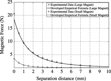
Figure 5. Comparison of the magnetic force between the empirical formula and the experimental data from K&J Magnetics.
Download figure:
Standard imageFor a certain magnet separation distance, the magnetic force direction depends significantly on the cantilever deflection. Figure 6 shows a frozen instant of the cantilever vibration which contains all physical variables required for mathematical modelling. The magnetic force FM can be decomposed into two components: FMx in the axial direction, perpendicular to the vibration direction, and FMy in the transverse direction, the main vibration direction.

Figure 6. Magnetic force decomposition.
Download figure:
Standard imageGenerally, the natural frequency of the harvester will vary with the variation of the magnetic force by varying the separation distance. It is well known that the natural frequency of the harvester depends directly on the effective stiffness and mass. As varying the magnetic forces does not change the mass of the structure, it is obvious that the change of the harvester natural frequency is due to the change of its effective stiffness. This allows us to model the effect of the magnetic forces FMx and FMy on the structural stiffness as nonconventional springs added to the system.
4.2. Equivalent stiffness from the axial force
Timoshenko (1937) addressed the effect of the static axial force on the natural frequency of a vibrating cantilever beam, where the natural frequency ω'n of a cantilever with a constant axial load is given by
where F is the tensile axial force, Yb is the Young's modulus of the material of the cantilever beam, I is the area moment of inertia, l is the span of the cantilever and ωn is the unloaded natural frequency of the cantilever.
As explained before, this change in natural frequency is due to the change in effective stiffness, and the net effect of the axial force can be modelled as a spring in the transverse direction. Let KF be the equivalent spring stiffness in the transverse direction representing the effect of the axial force on the cantilever natural frequency. From equations (7) and (13), KF is found to be
Therefore the natural frequency with an axial force is
If the vibration amplitude u is very small compared to the separation distance d of the magnets, θ will be very small so that FMx ≈ FM. Furthermore FM is approximately constant in this case. Thus

where KMx is the equivalent stiffness in the transverse direction introduced by the constant magnetic force FM.
4.3. Equivalent stiffness from the transverse force
The effect of the transverse force is the same as the effect of a force exerted by a spring. At the equilibrium position its value is zero and it is always acting against the vibration direction. Therefore this force is modelled as a spring with a stiffness derived as follows. Referring to figure 6 the transverse magnetic force is

and for small angles

Substituting equation (18) into (17), the transverse force becomes
This shows that the stiffness in the vibration direction can be described as

4.4. Effect on the natural frequency
The two effects of the magnetic force are modelled as springs in the transverse direction. Referring to equations (16) and (20), the total magnetic stiffness therefore is

A harvester with a passive tip mass and an additional stiffness KM in the transverse direction, as shown in figure 7, is thus equivalent to the magnetically tuned harvester shown in figure 3.
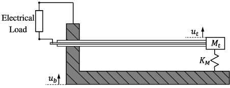
Figure 7. Harvester model with an equivalent stiffness representing the magnetic tuning effect shown in figure 3.
Download figure:
Standard imageThe resulting equivalent stiffness K of the harvester is the sum of the structural stiffness Kb and the total magnetic stiffness KM. Hence, the natural frequency is

4.5. Limitations of the model
The main assumption made in the calculations above is that the mode shape of the system is not changing significantly by the magnetic tuning mechanism. A second assumption used is that the amplitude of the tip deflection is always small compared to the separation distance, resulting in a small angle θ. In order to validate these assumptions, the system is simulated using the finite element software ANSYS. The simulated model consists of the short-circuited cantilever beam with a tip mass bonded to the cantilever which has the mass and geometry of the small magnet, as shown in figure 8. A constant axial force FM acts on the tip mass and a spring of stiffness KM (cf equation (21)) is attached to it in the transverse direction.

Figure 8. Calculated equivalent magnetic stiffness over the magnet separation distance. The insets show the mode shapes calculated for distances of 0.1, 1, and 10 mm using finite element simulation.
Download figure:
Standard imageFigure 8 shows the calculated equivalent magnetic stiffness KM over the magnet separation distance and the mode shapes at the first eigenfrequency calculated for distances 0.1, 1, and 10 mm.
It can be seen that for distances down to about 1 mm, the mode shape changes only very slightly. Also, θ can still be regarded small at this distance. At lower distances, the mode shape change is more significant. Equation (21) shows that for a very small separation distance between the two magnets, the equivalent stiffness will be very high, causing the beam to deform as if pinned at the tip and thus changing the vibration shape. As a side effect, this 'pinning' keeps the tip deflection low so that the assumption of small θ, resulting in a constant axial force, is still valid at low distances.
Due to the mode shape transition, the analytical model introduced earlier can only be accurate for distances above a certain minimum. Below this minimum, the deviation between model and measurement will increase considerably and the calculated natural frequency will be inaccurate due to the change of the effective stiffness and equivalent mass. Also, with the changed mode shape the strain changes sign over the length of the cantilever. This will cause some of the charge generated along the length of the beam to be cancelled out, reducing the generated power. For the investigated setup this minimum is around 1 mm, indicated by the dashed line in figure 8.
5. Results and discussion
According to IEEE (1966), the series resonance frequency represents the natural frequency of the mechanical system. Therefore, the change of the natural frequency can be determined by measuring the electrical admittance  of the bimorph for each distance. For this an impedance analyser (HP 4192A) was used and the bimorph was excited by a voltage of 500 mVRMS.
Figure 9 shows the experimental rig to measure the effect of the magnetic attraction on the natural frequency. A piezoelectric bimorph (SITEX-Module 427.0085.11Z from Johnson Matthey) with a cross section of 7.2 × 0.8 mm2 and a free length of about 40 mm and magnets with a face area of 8.5 × 2 mm2 and a thickness of 1.5 mm (from HKCM Engineering, manufacturing code Q08.5 × 02 × 01.5Ni48H) were used. The distance between the two magnets was adjusted using a micrometre screw.
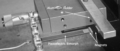
Figure 9. Experimental setup.
Download figure:
Standard imageFigure 10 shows the comparison of experimental and theoretical results, calculated according to equations (21) and (22). It should be kept in mind that the results are not fully analytical as they use the empirical formula (10) for calculating the magnetic force. For the calculations, the parameters of the bimorph and the magnets were taken from the datasheets. The assumed free length of the bimorph was adjusted to compensate for manufacturing tolerances and measurement errors so that the experimental and theoretical natural frequencies agreed for infinite distance between the magnets. The derivation of the analytical model used and an investigation of the influence of manufacturing tolerances are discussed in a separate paper (Al-Ashtari et al 2012). The figure shows that the theoretical results fit the experimental results well for distances down to 1 mm and it also shows that the bimorph natural frequency can be tuned significantly by changing the magnet separation distance. At 1 mm separation distance, about 71% increase in natural frequency compared to operation at large distances is obtained. At lower distances, distortion of the voltage signal is observed. This is due to the effect of the high magnetic force on the mode shape, as discussed earlier.

Figure 10. Harvester natural frequency versus magnet separation distance.
Download figure:
Standard imageNo experimental natural frequency for distances smaller than 1 mm can be given because at very small distances the resonance peak and phase drop of the system decrease drastically as shown in figure 11. The main reason for this is the change of the mode shape discussed earlier, causing the charges generated in different parts of the cantilever to cancel each other out.

Figure 11. Frequency sweeps of the electrical admittance of the harvester for different separation distances d.
Download figure:
Standard imageFigure 12 shows the experimentally identified structural damping ratio as the magnet separation distance changes. The damping ratio is calculated from the quality factor identified from the admittance sweeps according to IEEE (1966). The structural damping ratio decreases with decreasing distance down to 1 mm. This is explained by the fact that the damping ratio is proportional to the inverse of the natural frequency, cf (5); there is no significant effect on the equivalent mechanical damping coefficient B.
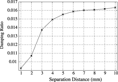
Figure 12. Measured harvester damping ratio versus magnet separation distance.
Download figure:
Standard image6. Conclusions
This paper presents a natural frequency tuning technique using magnetic force for a piezoelectric energy harvester that enables the harvester to operate and generate power efficiently in any environment with ambient vibration of different frequencies. The most important benefit is that the harvester natural frequency can be adjusted before and during operation without directly touching the vibrating structure. The results show that the proposed tuning technique can tune the harvester natural frequency in a wide range. For very small distances between the tuning magnets, the high magnetic force influences the mode shape of the harvester which has undesired effects on the generated voltage. For the tuning range where the influence on the mode shape is not relevant, a frequency increase of 71% was achieved. Also, the results show that the use of permanent magnets in tuning changes the damping ratio due to its dependence on the natural frequency, but that there is no significant influence of the magnetic tuning on the damping coefficient.
The empirical model that has been formulated for computing the magnetic attraction force between two permanent magnets as a function of their geometry, type and separation distance is very accurate and gives reliable results. For all distances where the vibrational mode shape is not influenced significantly by the magnetic force, the analytical model formulated for calculating the effect of the magnetic force on the energy harvester gives accurate results and can therefore be used to predict the magnets and distances required to tune any cantilever system within a desired frequency range.
Acknowledgments
The authors gratefully acknowledge the support of the German Academic Exchange Service (DAAD) and the Iraqi Ministry of Higher Education and Scientific Research (MoHESR).