
Abstract
We report a field emission-based, magnetic-less ion pump architecture for helping maintain a high vacuum within a small chamber that is compatible with miniaturized cold-atom interferometry systems. A nanostructured silicon field emitter array, with each nano-sharp tip surrounded by a self-aligned proximal gate electrode, is used to generate a surplus of electrons that cause impact ionization of gas molecules. A two-stage cylindrical electron collector, made of titanium, is used to increase the travel distance of the electrons, augmenting the ionization probability; gas ionization is subsequently followed by gettering of the ions by a negatively charged, annular-shaped titanium electrode. A proof-of-concept pump prototype was characterized using a 25 cm3 stainless steel vacuum chamber backed up by an external turbomolecular pump, a diaphragm pump, and a standard ion pump. Pumping action was observed with the electrostatic pump operating alone after an initial rapid rise of the chamber pressure due to electron/ion scrubbing. In addition, running the electrostatic pump in combination with the standard ion pump results in a lower vacuum level compared to the vacuum level produced by the standard ion pump acting alone. A proposed reduced-order model accurately predicts the functional dependence of the pressure versus time data and provides a good estimate of the characteristic pumping time constant inferred from the experiments.
Export citation and abstract BibTeX RIS
Introduction
The discovery of magneto-optical trapping of alkali vapor metals in the late 1980s [1–3] motivated a strong interest in developing miniaturized systems based on cold alkali atom interferometry. Consequently, chip-scale atomic clocks have been actively explored and commercialized over the last decade [4, 5]. More recently, miniaturized atomic sensors based on cold-atom interferometry have been investigated because of their inherent high precision; examples include gyroscopes and accelerometers for inertial navigation, and magnetometers and gravimeters for geological surveys [6–9]. Cold-atom interferometry requires ultra-high vacuum (UHV, pressure <10−9 Torr) to operate; therefore, chip-scale atomic sensors require miniaturized UHV pump technology resilient to alkali vapors that consumes power at levels compatible with device portability.
UHV can be maintained inside a chamber using a standard ion pump (figure 1), which has Ti flat plate/grid ion collector(s) negatively biased (~ −6000 V) with respect to a cylinder/cylinder array anode, and large permanent magnets that generate high magnetic fields (~0.2 T) within the pump volume [10]. Electrons are emitted from the ion collector(s) through field emission from surface asperities, or from bombardment of pre-existing ions in the inner volume of the chamber. The emitted electrons are 'trapped' by the magnetic field lines and move in a spiral towards the anode(s), causing the impact ionization of gas molecules. Gas ionization is followed by the generation of secondary electrons that also interact with the magnetic field lines and create ions through electron impact ionization, resulting in self-sustained plasma. The ions are pulled towards the ion collector(s), which capture(s) the ions. The pressure within the chamber drops as ions get buried within the collector(s) due to physical bombardment and chemical absorption. Some amount of secondary pumping can also occur when Ti is back-sputtered due to bombardment of high-energy ions; in this case, the back-sputtered Ti atoms react with gas molecules before depositing on the inner surfaces of the pump. The sputtered Ti atoms can also bury some of the gas molecules while depositing on the surfaces of the pump, constituting a third pumping mechanism [11].
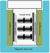
Figure 1. Schematic of a standard magnetic ion vacuum pump. The magnets are placed such that the magnetic field is transverse to the direction of propagation of the electrons, causing an E × B drift that, in addition to the Larmor motion, increases the path traveled by the electrons.
Download figure:
Standard image High-resolution imageScaled-down standard ion pumps have been reported, e.g. in [12]. However, such devices are not compatible with miniaturized cold-atom interferometry systems because of two main reasons, i.e. (i) as the diameter of the anode cylinder(s) scales down, the required magnetic field strength to achieve electron trapping increases [13], and (ii) as the size of the pump is decreased and the vacuum chamber gets spatially closer to the pump, the increased magnetic field from the ion pump alters the quantum states of the laser-cooled atoms, leading to incorrect measurements [14]. Turning off the magnetic field during measurements may offer a solution for implementing a chip-scale atomic sensor that is not affected by the magnetic fields of the magnetic ion pump that maintains the vacuum level within its vapor cell; however, this solution would not be ideal for a portable system. In an ion pump with permanent magnets, 'turning off' the magnetic field implies to physically move the magnets away from the vapor cell every time a measurement is made; for an autonomous system, this operation will require a built-in actuator that will consume power and introduce moving parts to an otherwise no-moving-parts system. An ion pump with electromagnets could be a better solution to switch off the magnetic field. However, given that the threshold magnetic field required for a miniature penning cell trap is high (~thousands of gauss [12]), this approach would likely be power hungry and deal with large currents, which is at odds with a portable application. In either case, the moment the magnetic field is turned off, the pump will stop and the chamber will immediately start pressurizing, which will narrow the window of opportunity for making the interferometry measurements. In commercial chip-scale atomic clocks, the problem posed by the magnetic field of the traditional ion pumps is partially addressed by using instead a non-evaporable getter (NEG) pump. However, NEGs are unable to pump any of the noble gases present in the chamber such as He, Ar, and N2 [4] and are inefficient in pumping alkali vapors [15]. In addition, He can easily permeate into the UHV chamber because of the very small size of its atoms. To this date, no satisfactory solution to the He leakage into UHV chambers has been demonstrated.
During the late 1960s and early 1970s, thermionic electron source-based, magnetic-less, electrostatic, UHV pump designs, such as the Orbitron pumps described in [16–18], were actively investigated. In a thermionic source, electrons are emitted from a hot surface (typically a tungsten filament heated by an electron current) if the thermal energy of the electrons overcomes the work function of the material. An Orbitron pump has three cylindrical, concentric electrodes, i.e. an inner electron collector, an outer grid electrode, and an outermost ion collector; a thermionic electron source is placed between the electron collector and the grid electrode (figure 2). Electrons emitted by the thermionic source orbit between the electron collector and the grid electrode, ionizing gas molecules present in the volume between the two electrodes; the ion collector captures the ions that are transmitted by the grid electrode. The potential of the electron collector is ~4000 V, the grid voltage is approximately 370 V, while the ion collector is at −1000 V. The thermionic emitter is grounded. Later designs of the Orbitron pump included a heated Ti source that periodically injected Ti molecules to increase the amount of getter material in the chamber, which increases the pumping speed. Due to the use of a Ti evaporation source, these pumps operate at power levels that are at odds with a chip-scale system [19].
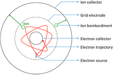
Figure 2. Cross-section schematic of an Orbitron pump; the electrodes are cylindrical in shape.
Download figure:
Standard image High-resolution imageIn this work, vacuum generation is demonstrated using a field emission electron source-based, magnetic-less, electrostatic ion pump architecture. The proposed pump design has four electrodes (figure 3), i.e. a silicon substrate with an array of nanostructured tips joined by a dielectric film to a Pt-coated proximal gate electrode with an array of apertures aligned to the array of tips (these two electrodes constitute the field emission electron source), a two-stage Ti electron collector, and an annular Ti ion collector. The two stages of the electron collector, i.e. a lower stage of smaller diameter and an upper stage of larger diameter, ensure an optimal trajectory of the electrons while minimizing the surface area for outgassing. In this design, a field emission source injects electrons into the pump cavity, and the electron collector pulls the electrons towards itself; the negatively charged ion collector acts as an electrostatic mirror for the electrons, causing their trajectory to bend, which increases the distance traveled by the electrons. Collision between electrons and gas molecules leads to the formation of ions which are pulled towards the ion collector, which getters them.
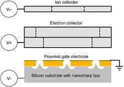
Figure 3. Schematic of proposed magnetic-less ion pump.
Download figure:
Standard image High-resolution imageThe field emission electron source used in this work is an array of single-crystal silicon nanosharp tips with an integrated proximal gate electrode with self-aligned grid apertures (i.e. each aperture is microfabricated concentric to its corresponding tip without introducing any misalignment). Field emission electron sources operate at room temperature and consume less power than thermionic electron sources to produce the same current. They can also operate at a lower vacuum level compared to thermionic sources [20, 21]. In addition, silicon field emitters can operate in atmospheres with residual reactive gases, e.g. an air leak [22]. Moreover, the high surface temperature of a thermionic electron source is incompatible with the reactive nature of the alkali vapor used in atomic sensors. Field emitters quantum tunnel electrons to a vacuum when the electrostatic field on the emitter tip surface is at least ~3 × 10⁷ V cm−1 [23]; nanosharp tips can generate such high electric fields at a low bias voltage (<50 V). Arrays of emitters can be implemented to increase the total emission current from the electron source provided the tip radii distribution is narrow [24]. The same field electron emitter array design used in this work has been shown to be compatible with rubidium vapor, which is an alkali metal commonly used in cold-atom interferometry [25].
There have been previous attempts to create a vacuum in a small chamber using a field emission electron source-based, magnetic-less ion pump architecture with moderate success. For example, in [26], a miniaturized modified Orbitron design in the form of a cylinder (diameter 250 μm and height 200 μm) was proposed. Using numerical models, it was predicted that the pump would function at an ion current of 16 nA with an ionization efficiency of 0.05% (i.e. ~2000 electrons are spent to create each ion); however, to the best of our knowledge a physical implementation of this design is yet to be demonstrated. Also, in [27], a pump architecture using a nanostructured silicon field emission electron source, an extracting mesh, and a single-crystal silicon getter was unable to demonstrate pumping; instead, the operation of the pump increased the chamber pressure due to outgassing caused by electron/ion scrubbing of the surfaces—a process that, regardless of the duty cycle of the electron source, released into the vacuum more gas molecules than the gas molecules captured by the getter. In addition, in [28], a carbon nanotube-based field emission electron source was used to create a vacuum. The pump architecture was shown to pump down a small cavity; however, it was only shown to pump down to the 10−4 Torr range, which is too high for a cold-atom interferometry system. In this work, pressures as low as 4.47 × 10⁻⁹ Torr were observed in a proof-of-concept demonstration with a 25 cm3 vacuum chamber. Earlier, our group demonstrated field emission-based pump designs using two different architectures that showed some degree of pumping [25, 29].
Reduced-order model of pump dynamics
In an isothermal ideal gas within a fixed volume, the relationship between the time derivative of the pressure, P, and the time derivative of the number of gas molecules inside the chamber, N, is
where Kb is Boltzmann's constant, T is the temperature of the gas, and V is the volume of the chamber. The rate of change in N is equal to the difference between the rate of change in the number of molecules that are injected into the chamber due to gas leakage and surface outgassing, Nleak, and the rate at which the gas molecules are gettered, which is equal to the ion current Ii multiplied by the yield coefficient of the gettering process, γ, divided by the ion charge q (the model assumes that all ions are singly ionized), i.e.

The ion current Ii is given by the electron impact ionization model [30], i.e.
where Ie is the electron current, L is the average length traveled by the electrons, and σ is the average ionization cross-section (a measure of the ionization probability that is a function of the potential of the ionization region [31]). Combining (1) through (3), and integrating over a time t assuming that  , L, and σ are constant, results in an expression for the chamber pressure as a function of time equal to

where Po is the chamber pressure at  , Pf is the ultimate pressure of the chamber, i.e.
  equal to
  , and τ is the characteristic pumping time constant given by
For a given vacuum chamber, a pump with larger pumping speed has associated a smaller τ and the chamber reaches a lower ultimate pressure. In order to minimize τ for a given chamber volume, the product of γ, L, σ, and Ie needs to be maximized. In [27], the electron current was greatly increased compared to that typically used in standard magnetic ion pumps, which caused as a collateral effect severe outgassing due to electron/ion scrubbing of the chamber surfaces, to the point that no pumping was observed—even though the number of ions implanted in the getter exceeded the original number of gas molecules in the chamber volume. In this pump design, we favored instead increasing the distance traveled by the electrons by using an arrangement of electrodes biased at certain voltages, so the trajectory of the electrons is significantly longer compared to the trajectory set by the parallel capacitor configuration used in [27]. Also, we carefully designed the electrode structure and optimized the bias voltages to reduce the percentage of electrons hitting the walls of the chamber, which should alleviate the scrubbing problem previously described. Additionally, a two-stage electrode electron collector allows for minimization of electrode surface area while allowing augmentation of the electron path length. In addition, the particle collectors implemented in this pump prototype use a more suitable getter material, i.e. Ti, to increase the yield of ion capture compared to the single-crystal silicon getter used in [27].
Finite-element modeling of the trajectory of the electrons
In order to study the trajectories of the electrons inside the chamber, multiple finite-element simulations using the commercial software COMSOL Multiphysics were conducted on a 3D model of a proof-of-concept pump prototype. The simulations did not model secondary electron emission by the electrodes or the ionization process. The architecture of the pump, as shown earlier in the schematic on figure 3, consisted of a flat field emission electron source, a two-stage electron collector, and an annular ion collector. The lower stage of the electron collector is a hollow cylinder of inner diameter 0.4'', while the upper stage has an inner diameter of 0.5''; the outer diameter for both stages is 0.6'' and the total electrode height is 0.2'' (0.1'' for each stage). The annular ion collector has an outer diameter of 0.6'' and an inner diameter of 0.2'' with a total electrode height of 0.2'' as well. The two-stage electron collector has several advantages compared to a single-stage version including (i) a smaller diameter at the bottom followed by a larger diameter at the top ensures that the path of the electrons is not obstructed, i.e. any electrons first entering the smaller diameter can start a curved trajectory around the collector, which is less obstructed than it would be if the collector had the same inner diameter throughout its height, and (ii) the 'step' formed at the interface of the lower and upper stages is in direct line of sight with the ion collector, which provides a collecting surface for back sputtered Ti molecules from the ion collector, providing protection to the electron source. The field emission electron source is modeled as a square plate with 4 mm sides. The initial kinetic energy of the electrons as they leave the surface of the electron source was assumed to be 100 eV, which corresponds to biasing a voltage between the chip substrate and the gate electrode equal to 100 V. From simulation results we determined that the initial energy of the electrons does not significantly influence the overall electron trajectories unless the initial energy is comparable to the energy associated with the bias voltage at the electron collector (i.e. 3000 V). Only above ~1000 eV, the initial electron energy significantly changes the electron trajectory. In contrast, the multi-kV bias voltages on the electron and ion collectors strongly influence the trajectories of the electrons.
Figure 4 shows the trajectories of 100 electrons evenly spread across the active area of the electron source. In this simulation, the ion collector was biased at −2500 V, while the electron collector was biased at +3000 V. The vacuum chamber, represented as a hollow cube block containing the overall architecture, is grounded. The gate-to-emitter bias voltage was not directly simulated because the separation between the gate electrode and chip substrate is much smaller than the other dimensions in the model. Instead, the square that represents the electron source was biased at 0 V, corresponding to the voltage of the gate electrode in the experimental setup. Looking at the simulation results, the initial trajectory of the electrons roughly describe a 'V' shape, with the electrons spreading out towards the top of the ion collector. The electrons then bend and are pulled back towards the collector, with most of them making two to three revolutions before striking the collector. The ion collector acts as an electrostatic mirror, visibly increasing the length of the trajectory of the electrons compared to the parallel capacitor case [27].
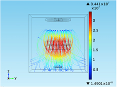
Figure 4. Simulation of the electron trajectories inside the pump using COMSOL Multiphysics. The sidebar corresponds to the velocity of the electrons in m s−1.
Download figure:
Standard image High-resolution imageFrom the simulations of the pump design using a range of bias voltages, it was determined that for the electrons to travel beyond the height of the electron collector, the magnitude of the bias voltage on the ion collector needs to be smaller or equal to the bias voltage on the electron collector. Biasing the ion collector with a voltage of larger magnitude than that of the electron collector results in a shorter electron trajectory as the electrons would be 'pushed' downward. At the same time, for successful gettering of ions by the ion collector, it is necessary to apply a large bias voltage to have a large projected range of the ions into the ion collector; however, if the energy of the ions is too high, they can cause excessive outgassing when striking the ion collector.
Experimental setup and testing procedure
Figure 5 shows the implemented proof-of-concept pump prototype, which is housed within a 25 cm3 vacuum chamber—a 1.33'' CF cube with rounded edges, while a schematic of the overall apparatus is shown in figure 6. The electrical connections of the pump prototype use three of the six 1.33'' CF flanges: the top flange, the bottom flange, and a flange on the side. The bottom flange is an electrical feedthrough with two pin connectors that energizes the field emitter array (FEA) chip: one connector provides an electrical signal to the gate of the FEA (ground), while the other connector provides an electrical signal to the silicon substrate of the FEA. The electrical feedthrough that energizes the chip can withstand up to 12 kV dc and 7.5 A dc as per the specifications of the vendor. One of the side flanges of the chamber is another electrical feedthrough with two pin connectors and identical specifications which is used to energize the titanium two-stage electron collector. The flange on the top is an electrical feedthrough with a SHV-5 connector used to energize the titanium ion collector; this connector can withstand up to 5 kV dc and 5 A dc as per the specifications of the vendor. The electron collector is designed such that a high current (typically 6A) can be passed through it using the two connectors of the feedthrough, which allows the electron collector to be heated up to >200 °C, before the ion pump experiments are conducted, to reduce the outgassing of the electrode while the pump is in operation. During operation of the electrostatic ion pump, however, the two connectors that energize the electron collector are shorted and a common bias voltage is applied. The chamber is connected to an external turbo pump backed up by a diaphragm pump and to a conventional magnetic ion pump through two of the side flanges using all-metal valves; the external pumps are used to lower the pressure inside the chamber before the proof-of-concept ion pump is activated. An ion gauge is connected to a side flange for monitoring the chamber pressure. With extended pumping and bake-out period, the system reaches a base pressure in the 10−9 Torr range.
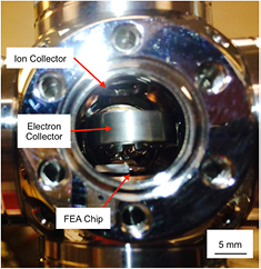
Figure 5. Optical picture of the pump setup through an open port in the 25 cm3 vacuum chamber, prior to attaching an ion gauge.
Download figure:
Standard image High-resolution image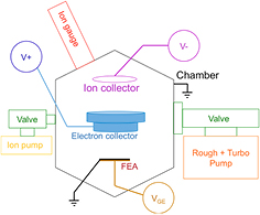
Figure 6. Schematic of the apparatus used to characterize the implemented proof-of-concept pump.
Download figure:
Standard image High-resolution imageThe FEA chip used in the proof-of-concept pump prototype is a 250 × 250 array of self-aligned, gated single-crystal silicon field emitters (figure 7). Each emitter tip has a diameter of ~5 nm. The tips and the gate electrode are coated with a 5 nm thick layer of Pt. A 2.5 μm-thick SiOx / SiNy dielectric stack separates the chip substrate from the gate electrode. The fabrication of the chip is described in a recent paper by our group [32]. During the activation of the field emission-based pump, the current emitted by the FEA was held constant at approximately 15 μA.
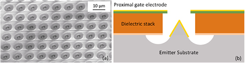
Figure 7. (a) SEM of a cluster of emitters, part of the silicon FEA; (b) schematic of a self-aligned gated tip.
Download figure:
Standard image High-resolution imageTo start the pump experiments, the all-metal valve connected to the diaphragm pump/turbo pump combo is opened to bring the pressure inside the chamber from atmospheric pressure down to the 10−7 Torr range. The chamber is then baked out overnight at a temperature of approximately 250 °C using a heating tape with integrated thermocouple. After this, the all-metal valve connected to the diaphragm pump/turbo pump combo is closed while the all-metal valve connected to the external conventional ion pump is opened, bringing eventually the pressure in the chamber down to 10−9 Torr range. The pressure is allowed to stabilize over a period of 38 h before the field emission-based pump was activated. In a typical pumping experiment, the electron and ion collectors are biased at +3000 V and −2500 V, respectively. The electron collector was biased at the maximum voltage that could be generated from the source-measuring unit (SMU) power supply we used (i.e. 3000 V for the Keithley 2657A), whereas the optimum ion collector bias voltage of −2500 V was determined experimentally by varying the ion collector voltage between −1000 V to −3000 V. From −1000 V to −2500 V, the chamber pressure dropped, resulting in faster pumping for a larger negative bias voltage. However, beyond −2500 V, the pressure was observed to increase, which was attributed to outgassing caused by bombardment of high-energy ions to the collector electrode surface. In a typical pumping experiment, the field emission-based pump is turned on and the all-metal valve to the external ion pump is kept open to ensure that the pressure in the chamber does not rapidly increase because a sudden increase in pressure within the chamber can lead to degradation of the FEA due to back-ion sputtering or to a micro-arc caused by a localized pressure build-up. Electron bombardment onto the electron collector causes initial outgassing when the electrostatic pump is turned on, resulting in a momentary raise in the chamber pressure. Subsequently, the pressure inside the chamber drops below the base pressure.
Experimental results and discussion
Prior to the assembly of the pump prototype, electrical characterization of the FEA chip was performed in a separate UHV chamber where the base pressure is constantly maintained at <5 × 10⁻¹⁰ Torr. SMUs Keithley 2657A were used to collect current-voltage (I–V) characteristics of the device in a triode configuration using an external electron collector. During the electrical characterization, the gate electrode was grounded, the emitter substrate was biased at a negative voltage which was swept from 0 V to 120 V in magnitude, and the collector electrode was biased at a constant voltage equal to +1000 V. Figure 8 shows a typical set of I–V characteristics of the chip. A turn-on voltage of approximately 34 V was measured, at which point the collector current was seen to rise above the noise level (~1 × 10⁻¹¹ A), and eventually at ~36 V it reached the nA range. For gate-to-emitter bias voltages below 40 V, the gate current is larger than the collector current and very similar to the substrate current, which implies that a high percentage of the gate current is due to leakage through the dielectric. However, the gate current reduces to about 0.7% of the emitter current when the gate-to-emitter bias voltage is ~60 V (~6 μA current emission), eventually reaching 0.3% at 120 V while delivering mA-level currents. Although this electron source is capable mA-level emission currents, μA-level electron current was sufficient to implement a working demonstration of the proposed pump architecture.
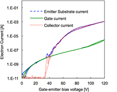
Figure 8. I–V characteristics of the silicon FEA.
Download figure:
Standard image High-resolution imageThe field emitted current I, in amperes, from a tip with emitting surface area α, in cm2, is [23]
where β, in cm−1, is the field factor that relates the applied gate-to-emitter bias voltage VGE, in volts, to the surface electric field F such that  , and ϕ, in eV, is the work function of the emitting surface. Figure 9 is the Fowler–Nordheim (FN) plot of the collector current Ic, i.e.
  versus
  , of the data shown in figure 8. As seen in (6), when
  is plotted against
  , the straight line thus described has a slope of -bFN/β if the current is field emitted. From the slope of the FN plot shown in figure 9, a field factor β equal to 1.89 × 106 cm−1 is obtained, assuming 6.35 eV as the work function of Pt. From finite element simulations of the electrostatics of the emitter tip, this field factor is found to be approximately equal to
  cm−1, where Rtip is the tip radius in nanometers [32]. Therefore, an estimate of the tip radius equal to 2.2 nm is obtained from the experimental data.
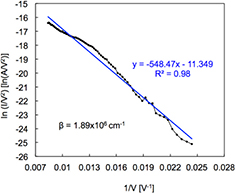
Figure 9. Fowler–Nordheim plot of the collector current reported in figure 8.
Download figure:
Standard image High-resolution imagePrior to the pumping experiments, the ionization process in the pump prototype was investigated. In some of these experiments the ion current was measured while the electron current was varied between 0.1 μA and 2.0 μA and the chamber pressure was kept at 1.0 × 10⁻⁶ Torr (figure 10(a)); in the other experiments, the ion current was measured at a constant electron current of 2.0 μA while the chamber pressure was varied between 1.0 × 10⁻⁷ Torr to 4.0 × 10⁻⁶ Torr (figure 10(b)). Looking at these results, it is evident that gas ionization was achieved and that the ionization is dependent on both the electron current and the chamber pressure. Analysis of the data suggests that the ion current has a linear dependence on the electron current for a given pressure, and a linear dependence on the pressure for a given electron current, which is what would be expected from the electron impact ionization model. However, these trends might not hold for the conditions of the pumping experiments because the ion current experiments involved electron currents that are an order of magnitude smaller than the electron current used in the pumping experiments. In addition, it is possible that secondary electrons are generated by ions bombarding the ion collector, which would cause an overestimation of the true ion current created by impact ionization.

Figure 10. (a) Ion current as a function of emitted electron current at a chamber pressure of 1.0 × 10⁻⁶ Torr, (b) ion current as a function of chamber pressure at a constant emitted electron current of 2 μA.
Download figure:
Standard image High-resolution imageFigure 11(a) shows a typical chamber pressure versus time characteristic when the system is pumped down using only the external ion pump; each data point in the figure is generated using a moving average of ten data points. After more than 33 h of pumping (118 800 s), the pressure inside the chamber stabilizes to a base value around 4.70 × 10⁻⁹ Torr; after 5 h of further pumping the chamber pressure remained stable. Figure 11(b) shows a typical pressure versus time data after the proof-of-concept field emission-based pump prototype is activated (the external ion pump is also pumping the chamber). The data were acquired starting at the peak pressure of 6.5 × 10⁻⁹ Torr. The initial rise in pressure when the FEA is turned on is attributed to outgassing due to electron and ion scrubbing. Subsequently, the pressure goes down and reaches a value below the base pressure level attained with only the external ion pump (4.47 × 10⁻⁹ Torr). It is possible that the order-of-magnitude increase in pumping rate when both the electrostatic ion pump and the external ion pump are turned on is due to the extended pumping by the external ion pump before activating the electrostatic ion pump, which could have removed most of the adsorbed gases from the surfaces of the system, resulting in a smaller outgassing rate that is easier to pump down afterward. More experiments are needed to elucidate this issue.
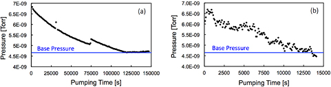
Figure 11. (a) Pressure versus time when the chamber is pumped with only the external ion pump, and (b) pressure versus time under the combination of the field emission-based ion pump and the external ion pump. In figure (b) the field emission-based ion pump is turned on at t = 0 while the external ion pump is still operating. Emission current is set at 15 μA while ion and electron collector bias voltages are set at −2500 V and 3000 V, respectively.
Download figure:
Standard image High-resolution imageGiven the functional dependence of the chamber pressure versus time predicted by (4), there is a linear relationship between the logarithm of the negative time derivative of the pressure and the pumping time, i.e.
where the negative of the inverse of the characteristic pumping time τ is the proportionality constant. Figure 12 shows the semi-log plot of the negative of the time derivative of the pressure versus time characteristic during pump-down, with the horizontal axis denoting the time since the beginning of operation of the field emission-based ion pump. The graph for figure 12 was plotted as follows: the first data point is an average of the ln(− dP/dt) values for first 300 s; then onward, averaging was done for every 2200 s so as to evenly distribute the data points over the entire period of 14 000 s. The high correlation of the linear least-squares data fit shown in figure 12 supports the functional dependence of the pressure versus time data predicted by (4), which states that the pumping rate of the pump is limited by its capability to create ions, which is limited by the number density of the gas inside the chamber.
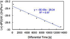
Figure 12. Semi-log plot of the negative time derivative of the chamber pressure versus time data shown in figure 11.
Download figure:
Standard image High-resolution imageUsing (5) with an estimated net pumped volume V of 25 cm3, an electron path length of ~2–3 cm (predicted by the finite element analysis previously discussed), and ionization cross-section of approximately ~10−17 cm2 (i.e. the cross-section for H2 [33], which is an abundant constituent of a high-vacuum atmosphere that started as air at standard conditions), and an electron current of 15 μA, results in a theoretical pumping time constant τ of ~10 000 s assuming a gettering coefficient γ equal to 1, i.e. that all ions created are gettered. The estimated τ from (5) would match the experimental time constant of 20 000 s derived from the slope of the plot in figure 12 if an average gettering coefficient γ of 0.5 is assumed. At 10−9 Torr-level pressure the atmosphere is mostly composed of H2, CO, H2O, CH4, and CO, with H2 the most abundant constituent (~80%) [34], and the gettering coefficient between titanium and different gas species varies between 0.06 (H2) to 0.7 (CO) [35].Therefore, it is reasonable to conclude that the actual gettering coefficient would lie between these two values.
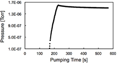
The proof-of-concept pump prototype was also characterized with the valve that connects to the external ion pump being closed (figure 13). The emission current, like in the experiments described before, was set at 15 μA. Similar to the experiment shown in figure 11(b), a initial rapid rise of the chamber pressure was observed once the valve that connected the eternal ion pump to the chamber was shut, as the pump prototype was not able to keep up with the rate of outgassing from the surfaces of the chamber due to electron and ion bombardment. However, the pressure eventually reaches a maximum and subsequently starts to drop. This experiment was discontinued after approximately 10 min of operation as a preventive measure to protect the FEA chip from prolonged back-ion bombardment at high pressure. We also ran experiments with all the external pumps turned off, yielding the same result, evidencing that the pumping was not caused unintentionally by the external pumps through a leaky valve. As expected, running the experiment with all pumps turned off, including the electrostatic ion pump, results in monotonic pressurization of the chamber. In addition, we also performed experiments with the ion collector turned off but the FEA chip and electron collector turned on, which resulted in the chamber pressure monotonically increasing.
Looking at the data shown in figure 13, it is evident that the release of gas molecules from the scrubbing of the surfaces is a major issue with our electrostatic pump because before pumping the chamber, it needs to pump the burst of molecules released by the surface scrubbing, which could be larger in volume than the original number of gas molecules within the volume. However, as shown in figure 11, if the electrostatic pump is put to work with the external ion pump, the chamber pressure reaches a lower vacuum level compared to that produced by the standard ion pump by itself. Therefore, the implemented pump prototype acts as an auxiliary pump of the magnetic ion pump, i.e. it requires external pumping as backup as it does not have enough capacity to evacuate the pressure surge due to outgassing.
Figure 13. Pressure versus time with the field emission-based pump alone (no back up from external ion pump).
Download figure:
Standard image High-resolution image
The results obtained in the experiments are encouraging but there are several pending issues that need to be addressed to demonstrate that the proposed pump architecture can work for extended periods of time, and to validate with more certainty the proposed reduced-order model. For example, the ion current experiments need to be conducted with electron currents similar to the electron currents used during pumping to corroborate the functional dependence of the ion current on the electron current and chamber pressure at these conditions. Also, the electrostatic pump needs to be characterized over a wider range of pressures, which could imply the development of a different electron source made of other emitting materials and/or include one or more extra proximal gates; it is possible that advanced high-voltage assembly micro/meso-scaled structures [36, 37] will be needed to integrate the proximal electrodes to achieve high current transmission and low leakage in the electron source. In addition, the characterization of the electrostatic ion pump in combination with a NEG pump is a very relevant demonstration that is yet to be done (in a practical application it would make no sense to include both a magnetic ion pump and an electrostatic ion pump if the motivation of the electrostatic ion pump is to avoid using magnetic fields). Finally, long-term pumping experiments that demonstrate the lifespan of the pump need to be conducted, as ion pumps are intended to work at UHV for very long periods of time without any servicing. In particular, showing the lifetime of the electrostatic pump to be beyond the expected life of the chip-scale atomic sensor is essential for the adoption of the pump technology by commercial atomic sensors.
Conclusion
A proof-of-concept demonstration of a novel magnetic-less ion pump compatible with cold-atom interferometry systems is reported. The pump uses a nanostructured silicon-based FEA as electron source together with a two-stage Ti electron collector and an annular Ti ion collector plate. Pumping action was achieved through electron impact ionization of gas molecules followed by the gettering action of the Ti ion collector. Experimentally, it was demonstrated that ionization is achieved as a result of electron emission, and that the prototype is capable of achieving by itself some level of pumping. The functional dependence of the pressure versus time data is described by a proposed reduced-order model, which is also capable of predicting the experimental pumping time constant if certain assumptions are made. Pumping action was observed with the electrostatic pump operating alone after an initial rapid rise of the chamber pressure due to the electron/ion scrubbing that seems to be inherently related to the operation of the electrostatic pump. In addition, running the electrostatic pump in combination with the standard ion pump results in reaching a lower vacuum level compared to the vacuum level produced by the standard ion pump acting alone.
Acknowledgments
The fabrication of the nanostructured field emission electron source was done by Arash Fomani from MIT and was carried out in the Microsystems Technology Laboratories, MIT. We would like to thank Daniel Farkas from ColdQuanta and David Johnson from Draper Laboratories for helpful discussions. This work was funded by the Defense Advanced Research Projects Agency/Microsystems Technology Office (DARPA/MTO) award number 022995-001 (program manager Robert Lutwak). Any opinions, findings, and conclusions or recommendations expressed in this publication are those of the authors and do not necessarily reflect the views of the US Government and therefore, no official endorsement of the US Government should be inferred.