
Abstract
This paper presents the direct three-dimensional (3D) fabrication of polymer scaffolds with sub-10 µm structures using electrohydrodynamic jet (EHD-jet) plotting of melted thermoplastic polymers. Traditional extrusion-based fabrication approaches of 3D periodic porous structures are very limited in their resolution, due to the excessive pressure requirement for extruding highly viscous thermoplastic polymers. EHD-jet printing has become a high-resolution alternative to other forms of nozzle deposition-based fabrication approaches by generating micro-scale liquid droplets or a fine jet through the application of a large electrical voltage between the nozzle and the substrate. In this study, we successfully apply EHD-jet plotting technology with melted biodegradable polymer (polycaprolactone, or PCL) for the fabrication of 2D patterns and 3D periodic porous scaffold structures in potential tissue engineering applications. Process conditions (e.g. electrical voltage, pressure, plotting speed) have been thoroughly investigated to achieve reliable jet printing of fine filaments. We have demonstrated for the first time that the EHD-jet plotting process is capable of the fabrication of 3D periodic structures with sub-10 µm resolution, which has great potential in advanced biomedical applications, such as cell alignment and guidance.
Export citation and abstract BibTeX RIS
1. Introduction
Micro-scale periodic three-dimensional (3D) structures have been widely used in many emerging applications, such as tissue engineering scaffolds [1], photonic crystals and meta-materials [2] and sensors and micro-devices [3]. In tissue engineering, scaffolds with a highly connected 3D structure are critical to support cell attachment/growth and construct tissues with predefined shape and size. Porous scaffold structures with optimal porosity, pore size and pore distribution are required to provide cells with sufficient oxygen and nutrient supply, and remove the waste generated throughout the metabolic process for better cell proliferation and tissue formation. While the relatively large structures and pores (generally >100 µm) are important for providing mechanical support and material transportation, micro-scale structures with their dimension similar to the size of the cell provides many advanced capabilities to regulate cell responses to the scaffold, such as cell alignment and cell guidance [4, 5].
Widely used extrusion and ink-jet printing-based solid freeform fabrication methods are limited in their achievable structural resolution that is mainly controlled by the nozzle size. Fused deposition modeling (FDM) [6] and precision extrusion deposition (PED) [7, 8] are capable of layered fabrication of 3D structures for thermoplastic biodegradable polymers, such as polycaprolactone (PCL). However, scaling down the nozzle size for better resolution will make the required extrusion pressure unpractical high for biopolymers with high viscosity, since the extrusion pressure scales up much faster when the nozzle diameter is decreased according to the Hagen–Poiseuille equation.
Electrohydrodynamic jet (EHD-jet) printing is a high-resolution printing method, in which the printed materials, ranging from nanoparticles [9–11], polymer solution or polymer melt [12, 13], ceramic solution [14] to composite materials [15], are subjected to a high electrostatic field to form a Taylor-cone structure and a fine jet issued from the cone. The diameter of the jet is significantly smaller than the nozzle diameter, which can overcome the limitation of the nozzle size and produce micro and nano-scale features. The electrohydrodynamic (EHD) phenomenon was examined by Zeleny back to 1917 [16], and was then examined both theoretically and experimentally, which provided insightful understanding of the phenomenon along with many important applications.
The parameters for EHD-jet plotting include material properties of the ink (e.g., viscosity, density, conductivity and permeability) and operational conditions such as applied voltage/electrical field, pressure/flow rate and substrate to nozzle distance. It is important to point out that widely used electrospray [17–20] and electrospinning [21–26, 37–39] utilize the unstable electrohydrodynamic behavior, while EHD-jet plotting needs to avoid unstable behavior to achieve well-controlled placement of the printed structures. In 2D EHD-jet printing has been used to fabricate micro/nano-scale patterns in the form of droplet in the pulsation mode for the applications of bio-sensing [27, 28], drug encapsulation [29, 30] and AFM cantilever modification [13]. While isolated fine droplets can be flexibly controlled for 2D patterning, it is difficult to directly use them for 3D fabrication. EHD-jet plotting with a stable jet, even though is still predominately used in 2D fabrication [9], provides good potential for the fabrication of 3D structures by using continuous filaments instead of isolated droplets, if the filament formation and solidification can be well controlled. There are some initial attempts to fabrication of 3D polymeric structures using EHD-jet printing [12, 23]. However, due to the difficulty of solvent evaporation, these approaches are still limited in the achievable resolution and controllability.
Working in a stable jet region is critically important for the freeform fabrication of 3D structures using EHD-jet printing. Depending on different process conditions, axisymmetric instability, in which droplets break up from the jet, or nonaxisymmetric instability (i.e. whipping) will disrupt the stable cone jet [31, 32]. These instabilities are required for electrospray and electrospinning, but devastating for 2D and 3D fabrication requiring precision position control. Process parameters as well as materials used have to be carefully chosen to obtain a stable cone-jet. As pointed out [33], very low conductivity liquids such as toluene and hexane may not have any cone-jet mode. There exists a minimum flow rate threshold for cone-jet mode [34], and a maximum flow rate [35] above which whipping instability is developed. For the fabrication of the 3D structure, the upper layer filaments need to span over the gap underneath them. Quick solidification of the plotted filaments against the sagging down effect is also critical.
In this paper, we present direct 3D fabrication of polymer scaffolds with sub-10 µm structures using electrohydrodynamic jet plotting of melted thermoplastic polymers. For the highly viscous biodegradable thermoplastic polymer used (PCL), traditional extrusion-based fabrication approaches cannot fabricate micron-scale features, due to the excessive pressure requirement. We successfully apply EHD-jet plotting technology with melted PCL for the fabrication of 2D patterns and 3D periodic porous scaffold structures for potential tissue engineering applications. Process parameters (e.g. electrical voltage, pressure, plotting speed) have been thoroughly investigated to achieve reliable jet printing and filament formation. We demonstrate for the first time that this EHD-jet plotting is capable of the fabrication of 3D micro-scale structures. The well-aligned filaments and channels will have great potential in advanced biomedical functions, such as cell alignment and guidance, as those that have already demonstrated in 2D applications [5, 40].
2. Materials and methods
2.1. Materials used for EHD-jet plotting
PCL pellets were purchased from Sigma-Aldrich (Milwaukee, WI) with an average Mn of 45 000 g mol−1 and melting point from 56 to 64 °C. As a biocompatible and biodegradable polymer that has been approved by the Food and Drug Association (FDA), PCL has been widely used for the fabrication of tissue engineering scaffolds. The thermal as well as rheological properties have been extensively covered in [8], which make PCL a great candidate to be used in the fabrication of micro-scale structures by EHD-jet plotting in its melting phase. The temperature gradient can quickly solidify the jetted PCL to form well-controlled fine 3D structures with sub-10 µm resolution.
2.2. System setup for EHD-jet plotting
The EHD-jet plotting platform was composed of four subsystems: a three-axis (XYZ) precision stage, a pneumatic dispensing system with precision pressure regulator, a thermal control system and a high voltage supply (figure 1). The XYZ precision stage was located on an optical table to reduce vibrational noise. Three linear stages that were configured in XYZ directions with 100 nm repeatability and accuracy were used to position the plotting nozzles to the programmed locations. The stage provided a displacement range of 100 × 100 × 50 mm. A high-resolution camera with a maximum resolution of 0.5 µm was used to monitor the deposition process.
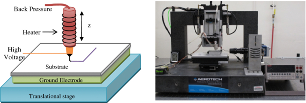
Figure 1. Schematic of the EHD-jet printing setup and experimental testbed for EHD-jet printing.
Download figure:
Standard imageA pneumatic syringe was used to provide the pressure of the EHD-jet plotting process and keep the required flow rate. Two deposition nozzles (one stainless steel nozzle with an ID of 152.4 µm and OD of 304.8 µm, one conical shape nozzle with an ID of 51 µm and OD of 152 µm) were used with 3 mL syringes for EHD-jet printing. The pneumatic system with a precision regulator can provide a maximum pressure of 10 psi with 0.05 psi resolution. After adding a heating tape and a thermal control system, the e-jet printing system was capable of processing thermoplastic materials (e.g. PCL) in this study. The heating tape was wrapped around the syringe to melt the thermoplastic polymer loaded inside the syringe. A thermocouple was mounted close to the nozzle to provide temperature feedback to a thermal controller. A proportional–integral–derivative (PID) controller regulated the power of heating tape to achieve the desired temperature. The thermal control system has a resolution of 0.5 °C with a maximum reachable temperature of 250 °C. PCL were melted and printed onto the substrate under the applied electrical voltage between the nozzle and the grounded plate. The electrical potential between the nozzle and the substrate is controlled by a high-voltage source meter (Keithley 2410) which can provide voltage up to 1100 volts. The substrate (1 mm thick glass slide) rests on an aluminum-coated silicon wafer that provides an electrically grounded support. The substrate and the underneath ground electrode was displaced by the XY-stage.
2.3. EHD-jet plotting process
In this study, a short nozzle–substrate distance (170 µm) was chosen to utilize the stable jet region and avoid potential whipping instability. The effects of other process parameters (applied voltage, pressure, printing speed) on the EHD-jet plotting process were investigated to obtain the most appropriate set of process conditions for 2D patterning and 3D structure fabrication. Two types of printing nozzles (with orifice sizes of 152.4 µm and 51 µm) were used to evaluate the effect of nozzle size to the plotting results. In order to quantify the results, 12 filaments were deposited with 40 µm centerline distance for each parameter condition (voltage, pressure and printing speed). The diameter of these filaments was measured by SEM. The results were expressed as mean ± standard error.
2.4. Two-dimensional patterning and 3D freeform fabrication using EHD-jet plotting
After a stable jet is obtained, two-dimensional PCL patterns were directly plotted on the substrate e.g. using a fountain pen. Complex 2D patterns such as spiral-in circle and square, and a freeform flower pattern, were printed to demonstrate the capability of the EHD-jet plotting. Porous 3D PCL scaffolds with fully interconnected inner structures were fabricated using EHD-jet plotting. The PCL pellets were melted at 80 °C and then EHD-jet plotted. The overall scaffold dimensions are 2.5 × 2.5 mm, and the distance between the centerlines of two filaments is 30 µm. The filaments of PCL were deposited with a layered pattern of 90° orientation to the previous layer to create the porous structure with eight layers. Because PCL was highly viscous and can quickly solidify after being extruded, no supportive material was required. The G-code program is used to generate the tool path of the printing system for both 2D and 3D pattern in this study. In the case of a complex pattern, the computer-aided design (CAD) software package can be used to generate the G-code for a specific structure design and then feed into the motion controller to provide the motion of the printing system.
2.5. SEM and microscope morphology characterization
The shape of the cone-jet of the EHD-jet printing was observed by the high-resolution video camera. The morphology of EHD-jet plotted PCL patterns and 3D scaffolds was characterized using SEM (S-3500, Hitachi Instruments Inc., Tokyo, Japan). The scaffolds were sputter-coated with gold, and viewed at a 10 kV accelerating voltage. The filament size and spacing were measured and calculated from SEM images using the image analysis software.
3. Results and discussion
3.1. Stable cone-jet formation of melted PCL
In electrohydrodynamic printing, the applied electric field, and the resulting electric stress (figure 2(a)), deforms the meniscus at the nozzle end into the Taylor cone, and eventually produce drops or a jet from the cone shape. Generally, as the applied electric field strength increases, different electrohydrodynamic printing modes can be observed, transitioning from pulsating mode to stable jet, unstable multiple jets [17]. For the melted PCL at 80 °C, when the nozzle to substrate gap was kept at 170 µm, as we increased the voltage from 500 V, a meniscus and Taylor cone was gradually forming at the tip of the nozzle (figure 2(b)). However at a voltage lower than 800 V, there is no observed drip and jet generated from the cone. When the voltage was increased to about 825 V, a stable jet began to be ejected from the cone. The jet remained stable, but both the radius and elongation of the electrified cone became smaller (figure 2(d)), as the voltage increased. When the applied voltage was increased to about 1100 V unstable multijets appeared, as shown in figure 2(e). In our experimental condition, we did not observe any pulsating printing mode (single drop printed onto the substrate), partially due to the high viscosity of the melted PCL. It is difficult for melted PCL to obtain enough electric stress to overcome the surface tension at the meniscus to form a fine drop.
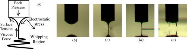
Figure 2. (a) Forces on Taylor cone in EHD processing. (b) Small meniscus without jet or drip at the nozzle tip at 600 V. (c) and (d) Stable cone-jet at 900 and 1050 V. (d) Unstable multijet at high electric field strength.
Download figure:
Standard imageDue to the high viscosity of the melted PCL, the stable cone-jet formation requires relatively long transient time (about 25 s) to reach equilibrium, which indicates that any serious disruption of the cone-jet structure may end up with defects in the fabricated structures. Figure 3 shows a typical cone-jet formation sequence after which the stable cone-jet mode is remained and precise patterning and plotting can be performed continuously.
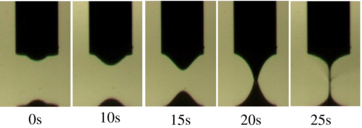
Figure 3. Time sequence of cone-jet formation.
Download figure:
Standard image3.2. Characterization of the EHD-jet plotting process
Obtaining stable electrohydrodynamic cone-jet mode requires the proper selection of the process parameters that include electrical voltage, pressure and plotting speed. These process conditions need to be thoroughly investigated to achieve reliable jet printing and filament formation. In this study, the nozzle–substrate gap was fixed at 170 µm to achieve large enough electric strength to form the stable cone-jet. At this small standoff height, the jet is kept at the stable and straight region, and the effect of whipping instability is minimized. The small standoff height also enables the process to response promptly to the abrupt path change when fabricating complex features with sharp turns and small corners. In contrast, if a large nozzle–substrate gap is used, the long unsettled partially solidified filament between the nozzle and the substrate increases the difficulty in plotting patterns with large curvature. To observe the effect of different process conditions on the cone-jet shape and the plotted filaments, one process parameter (from electrical voltage, pressure and plotting speed) was changed at a time while keeping others constant.
3.2.1. The effect of voltage on the EHD-jet plotting process
The applied voltage played the most important role in the EHD-jet printing process. As shown in figure 2, as the voltage increases, we can observe the formation of the meniscus at the nozzle tip below the critical voltage, a stable cone-jet within a proper range of the applied voltage and then unstable multijets with too high voltage. The unstable jet is not practically useful for precision fabrication. In this section, we identified the possible voltage range for stable jet and inspected the resulting filament geometry. Filaments were plotted onto the substrate with a spacing of 40 µm. As the effect of the voltage was investigated, a pressure of 4.0 psi and a plotting speed of 1.6 mm s−1 are chosen for the nozzle with 152.4 µm orifice, and a pressure of 1.8 psi and a plotting speed of 1 mm s−1 are chosen for the nozzle with 51 µm orifice.
The voltages between 700 V and 1050 V with a step of 25 V were applied to the nozzle, and the resulting cone-jet shape was observed from the high-resolution camera along the plotting direction and from the side. Clearly there exists a lower bound threshold voltage (between 800 V and 825 V for this configuration) to continuously jet melted polymer, under which the stable cone-jet structure cannot be maintained. At a relative low voltage (825 V for the 152.4 µm nozzle and 850 for the 51 µm nozzle), a skewed cone-jet was observed (figure 4), in which the jet was inclined to the substrate along the plotting direction. As the voltage increased, the skew cone-jet mode was switched to straight cone-jet with minimal feature variation at around 900 and 925 V for the large nozzle and small nozzle respectively. After the voltage was further increased, although a straight and stable cone-jet was observed from the camera, the plotted filaments became winding and lose controllability for precision fabrication. Moreover, the amplitude of winding increased with the increase of the voltage. This behavior can be explained by the specific material property of PCL and the jetting speed. In electrohydrodynamic printing, the jetting speed increases with a larger voltage and the resulting larger electric field strength. At the low voltage, the jetting speed was lower than the plotting speed of the stage, and the highly viscous force of the melted PCL deformed the cone-jet. As a result, the skewed cone-jet was observed. When the jetting speed matched the plotting speed, a straight cone-jet was obtained. When the voltage was too high, the jetting speed exceeded the plotting speed. The high viscosity of the plotted and semisolidified PCL filaments makes it difficult to reflow on the substrate. Thus the winding filaments were obtained to absorb the overplotted length due to speed mismatch.
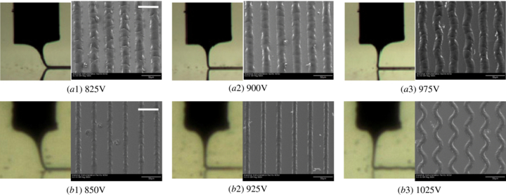
Figure 4. The cone-jet shape and jet printed filaments at different voltages. (a1)–(a3) Results from a nozzle with 152.4 µm orifice. (b1)–(b3) Results from a nozzle with 51 µm orifice. All scale bars 50 µm.
Download figure:
Standard imageThe plotted filaments at different voltages were observed in a SEM, and their dimension was measured as mentioned in section 2.3, as shown in figure 5. The average strand widths of about 22 µm and 13 µm were obtained respectively for two nozzles. For the large nozzle, when the applied voltage is very low (825 V) and closed to the threshold voltage, a large variation in filament dimension was observed. However, the filaments plotted by other skewed cone-jets modes at 850 and 875 V have almost the same variation in their dimension when compared to the filaments plotted by the straight cone-jet from 900 to 950 V, which indicates that the skewed cone-jet can also be possibly used for precision fabrication to enlarge the operation range.
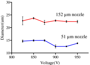
Figure 5. Filament width at different voltages.
Download figure:
Standard image3.2.2. The effect of plotting speed
As observed from the previous section, the potential mismatch between the jetting speed and the plotting speed will affect the cone-jet shape and the plotted filaments on the substrate. In this section, we directly investigated the effect of the plotting speed on the printing process and fabricated filaments, while the jetting speed was kept constant by using the fixed voltage and pressure. A pressure of 4.0 psi and a voltage of 900 V were chosen for the nozzle with 152.4 µm orifice, and a pressure of 1.8 psi and a voltage of 925 V were chosen for the nozzle with 51 µm orifice.
When plotting at a small plotting speed for both nozzles, winding filaments were observed (figure 6). As the plotting speed increased, the filaments become straight gradually. After the plotting speed was further increased, the skewed cone-jet appeared with straight filaments left on the substrate. This specific behavior indicated the importance of matching the plotting speed with the jetting speed. When the plotting speed is lower than the jetting speed, the overplotted filaments were buckled on the substrate, since it is difficult for the highly viscous filament to reflow on the substrate. A vibrating cone-jet, similar to whipping instability, was observed due to the viscous dragging force from the winding settlement of the PCL filament. The jet vibration gradually disappeared with the increased plotting speed, and the stable cone-jet and straight filaments were obtained, which confirm that the jet vibration at low plotting speed are not whipping instability, but from the interaction between the cone-jet and the printed winding filaments. If the plotting speed is too high, the viscous dragging force from the printed features deformed the cone-jet to the skewed cone-jet. The diameter of the filament has been evaluated as mentioned in section 2.3. For the straight filaments fabricated by the stable cone-jet and slightly skewed cone-jet, as the plotting speed increases, the plotted filament width shows a decreasing trend. For the 152.4 µm nozzle, the line width decreased from about 25 to 17 µm, as the plotting speed increased from 1.2 to 2.4 mm s−1. For the 51 µm nozzle, the line width decreased from about 13 to 7 µm, as the plotting speed increased from 0.8 to 2 mm s−1 (figure 7). The results indicate that the PCL jet or semisolidified filament can be stretched with the reduced filament diameter. The plotting speed can be used as a method to adjust the dimension of the fabricated features.

Figure 6. The cone-jet shape and the jet printed filaments at different plotting speed. (a1)–(a3) Results from a nozzle with 152.4 µm orifice. (b1)–(b3) Results from a nozzle with 51 µm orifice. All scale bars 50 µm.
Download figure:
Standard image
Figure 7. Filament width at different plotting speeds.
Download figure:
Standard image3.2.3. The effect of pressure
It is well known that the pressure or the flow rate can affect the cone-jet shape and jet stability [35]. The required pressure range for maintaining stable-jet plotting is determined by the nozzle size and other process conditions. The pressure from 3.6 to 5.6 psi was applied to the large nozzle with an applied voltage of 900 V and a plotting speed of 1.6 mm s−1. For the small nozzle, the pressure from 1.2 to 3 psi was applied with a voltage of 925 V and a plotting speed of 1 mm s−1. In electrohydrodynamic printing, generally larger flow rate will make the jet less stable and produce whipping instability. However, for EHD-jet printing of melted PCL, we observed vibrating jet and winding filament at a low pressure (figure 8). As the pressure increased, the stable jet and the skewed cone-jet appeared gradually, and straight filaments were achieved. This phenomenon is again the result of the high viscosity of the melted PCL jet and interaction between the cone-jet and the printed filaments on the substrate. With a small flow rate at low pressure, a thin jet was obtained. The electric stress provided large acceleration and high speed of the ejected jetting. This jetting speed was larger than the plotting speed, thus winding filaments and vibrating jet were observed. As the pressure increased, the large flow rate produced a thick jet. With similar electric stress (from the same voltage), less acceleration was applied to the jet, resulting in smaller jetting speed. Thus the jetting speed gradually matched the plotting speed, and then was lower than the plotting speed. As a result, straight filaments and skewed jet were observed. This explanation was further supported by the increased filament width (indicating larger flow rate) along with the increase of the pressure, as shown in figure 9.
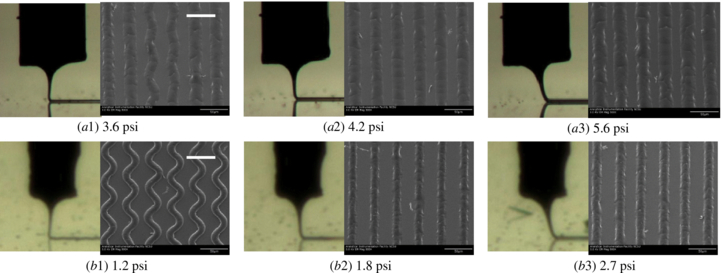
Figure 8. The cone-jet shape and the jet-printed filaments at different pressures. (a1)–(a3) Results from a nozzle with 152.4 µm orifice. (b1)–(b3) Results from a nozzle with 51 µm orifice. All scale bars 50 µm.
Download figure:
Standard image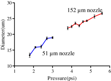
Figure 9. Filament width at different back pressures.
Download figure:
Standard image3.2.4. The scaling effect of the nozzle size
The size of the nozzle orifice greatly impacts the dimension of the EHD-jet printed structures. The previous research mentioned a general scaling relationship between the nozzle size and the jet diameter that the jet diameter is proportional to the square root of the nozzle size [36]. It is difficult to directly apply this scaling law to the melted EHD-jet printing, since the previous models were built on pure liquid phase ink. For the EHD-jet printing of melted PCL, the temperature-induced viscosity change and even phase change in the jet can make the theoretical modeling very complex and different. But we did observe the better printing resolution (smaller filament dimensions) by using a 51 µm nozzle than that by using a 152.4 µm nozzle. The filament dimension was roughly reduced by a factor of 2.
3.3. Fabrication of 2D patterns and 3D structures
One of the most critical steps in EHD plotting is to match the plotting speed with the jetting speed; the latter is affected by the applied voltage and the pressure. Small plotting speed can result in winding filaments and jet instability, while too large plotting speed can result in the severely skewed jet and large lag in plotting, which will degrade the controllability and precision of plotting. In our plotting practice, the straight cone-jet or the slightly skewed jet was used for the fabrication to avoid the winding of the filaments.
High-resolution precisely controlled fabrication of 2D patterns and 3D structures was achieved using the EHD-jet plotting of melted PCL. Using the small nozzle with 51 µm inner diameter, various complex two-dimensional patterns were printed onto a glass substrate. Figure 10 shows a spiral-in round-shape pattern, a spiral-in square-shape pattern and one freeform flower pattern plotted by PCL filaments. The smallest line width was less than 5 µm, which is at least one to two orders of magnitude smaller than direct melt extrusion-based fabrication approaches. Because a small nozzle–substrate gap was chosen at 170 µm, there is less lagged jet/filament in between the nozzle and the substrate. As a result, the EHD-jet plotting process can respond a well-to-sharp geometric change. Patterns with a turning radius as small as 10 µm can be achieved reliably.
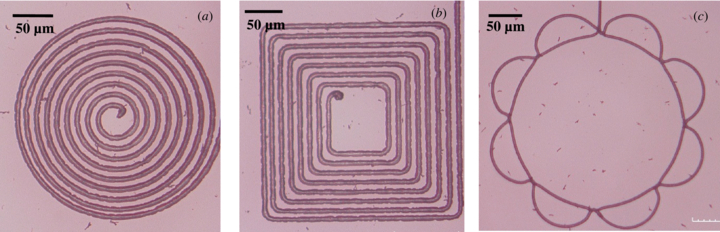
Figure 10. Two-dimensional patterns fabricated by electrohydrodynamic jet printing of melted PCL. (a) Spiral-in circle pattern. (b) Square shape pattern. (c) A flower pattern.
Download figure:
Standard imageThree-dimensional woodpile scaffold structures were fabricated using EHD-jet plotting of melted PCL. The overall scaffold dimensions are 2.5 × 2.5 mm; the distance between the centerlines of two filaments is 30 µm. The filaments of PCL were deposited with a layered pattern of 90° orientation to the previous layer to create the periodic porous structure. During the fabrication, we kept the standoff height of 170 µm while slightly adjusting the applied voltage to count for the change of electrostatic field strength due to the plotted layers on the substrate. In the plotting of 3D structures, selection of plotting speed is even more important, as the plotted filaments were plotted across a large gap without any support. To prevent the sagging effect, the plotting speed needs to be high enough so that the viscous force from the jet and filament can produce a self-supported structure. Figure 11 demonstrates a porous 3D lattice-structured scaffold of PCL with fully interconnected inner architectures that were fabricated using the direct electrohydrodynamic hot jet plotting approach. Figures 11(b)–(d) clearly demonstrate the layered pattern and the fully interconnected pores of the fabricated scaffold micro-architecture. The uniformity of the pores and the filaments indicates the applicability of using the developed electrohydrodynamic hot jet plotting process to fabricate structures at the micro-scale. The diameter of the filament is about 6 µm. It is very difficult, if not at all impossible, to achieve such resolution with traditional fabrication approaches, such as fused-deposition modeling (FDM), in which the deposited filament diameter is largely determined by the nozzle diameter. Scaling down the nozzle size for better resolution with traditional fabrication approaches will make the deposition pressure unpractical high for high viscous biopolymers.
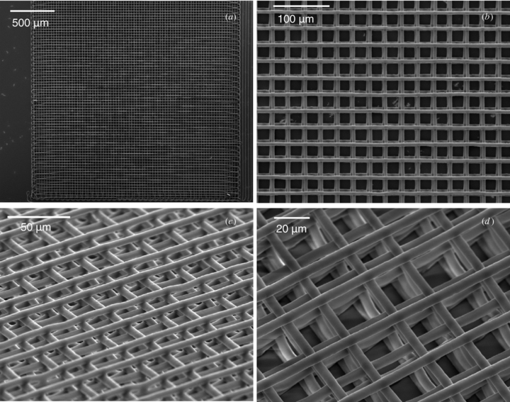
Figure 11. Three-dimensional scaffold structures fabricated by direct EHD- jet plotting of melted PCL. (a) Overview of the scaffolds. (b) Detailed view of the plotted filaments. (c) and (d) Tilted views show the layered structure of the 3D scaffold.
Download figure:
Standard image4. Conclusion
In this study, we applied electrohydrodynamic hot jet plotting technology with melted biodegradable polymer (polycaprolactone, or PCL) for the fabrication of 2D freeform patterns and 3D periodic porous scaffold structures for potential tissue engineering applications. Stable cone-jet formation, cone-jet shape and plotted filaments under different process conditions (e.g. electrical voltage, pressure, plotting speed) have been thoroughly investigated to achieve reliable jet printing. The most important step in selecting the proper set of process parameters is to match the plotting speed and jetting speed that are controlled by the applied electrical voltage and pressure. We have demonstrated for the first time that 3D periodic structures with the layered pattern and the fully interconnected pores can be fabricated by the electrohydrodynamic hot jet plotting process with sub-10 µm resolution using high viscous biodegradable polymers. The achieved filament diameter is one to two orders of magnitude smaller than traditional melt extrusion-based fabrication approaches. The EHD-jet plotted micro-scale structures have great potential in advanced biomedical applications, such as cell alignment and guidance of cell growth.
Acknowledgments
This work was supported in part by the National Science Foundation under grant Award CMMI-1129817 and CMMI-1233176.