

Abstract
Energy harvesting from ubiquitous ambient vibrations is attractive for autonomous small-power applications and thus considerable research is focused on piezoelectric materials as they permit direct inter-conversion of mechanical and electrical energy. Nanogenerators (NGs) based on piezoelectric nanowires are particularly attractive due to their sensitivity to small-scale vibrations and may possess superior mechanical-to-electrical conversion efficiency when compared to bulk or thin-film devices of the same material. However, candidate piezoelectric nanowires have hitherto been predominantly analyzed in terms of NG output (i.e. output voltage, output current and output power density). Surprisingly, the corresponding dynamical properties of the NG, including details of how the nanowires are mechanically driven and its impact on performance, have been largely neglected. Here we investigate all realizable NG driving contexts separately involving inertial displacement, applied stress T and applied strain S, highlighting the effect of driving mechanism and frequency on NG performance in each case. We argue that, in the majority of cases, the intrinsic high resonance frequencies of piezoelectric nanowires (∼tens of MHz) present no barrier to high levels of NG performance even at frequencies far below resonance (<1 kHz) typically characteristic of ambient vibrations. In this context, we introduce vibrational energy harvesting (VEH) coefficients ηS and ηT, based on intrinsic materials properties, for comparing piezoelectric NG performance under strain-driven and stress-driven conditions respectively. These figures of merit permit, for the first time, a general comparison of piezoelectric nanowires for NG applications that takes into account the nature of the mechanical excitation. We thus investigate the energy harvesting performance of prototypical piezoelectric ceramic and polymer nanowires. We find that even though ceramic and polymer nanowires have been found, in certain cases, to have similar energy conversion efficiencies, ceramics are more promising in strain-driven NGs while polymers are more promising for stress-driven NGs. Our work offers a viable means of comparing NG materials and devices on a like-for-like basis that may be useful for designing and optimizing nanoscale piezoelectric energy harvesters for specific applications.
Export citation and abstract BibTeX RIS

Content from this work may be used under the terms of the Creative Commons Attribution 3.0 licence. Any further distribution of this work must maintain attribution to the author(s) and the title of the work, journal citation and DOI.
Introduction
Nanogenerators (NGs) based on piezoelectric nanowires have been found to outperform bulk or thin-film devices [1–5] and are thus attractive from the point of view of VEH. Piezoelectric ceramic nanowires, including ZnO [3, 4, 6–9], GaN [10, 11], BaTiO3 [12–17], PbZrxTi1-xO3 [18–26], [Pb(Mg1/3Nb2/3)O3]1−x−[PbTiO3]x [27], ZnS [28], CdS [29] and InN [30], as well as piezoelectric polymer nanowires, including poly(vinylidene fluoride) (PVDF) [2, 31–35] and its copolymers [1, 36, 37], have been incorporated into NGs of various geometries over the last few years. Piezoelectric nanowires based on biological polymers [38, 39] have also been suggested for applications in NGs. The NGs reported have been shown to have promising energy harvesting performance in terms of the electrical output generated. In a few cases, the energy conversion efficiency, χ, of the piezoelectric nanowires has been evaluated as the ratio of the maximum electrical energy generated per cycle to the elastic energy supplied to the nanowires by the excitation. However, the mechanical driving mechanism in each case was very different, including the mode of excitation and its frequency. Yet the effect of this on NG performance has rarely been considered thereby making a reasonable quantitative comparison of materials for specific NG applications challenging. Broadly speaking, as pointed out by Bowen et al NG-driving modes can be categorized as inertial and kinematic [40]. Here, we sub-categorize kinematic VEH using NGs as stress-driven, where the NG is subjected to an applied sinusoidal stress, T = Re(T0eiωt) and strain-driven, where the NG is subjected to an applied sinusoidal strain, S = Re(S0eiωt). We show, using a straightforward analysis, that for SNGs and TNGs, ηS and ηT defined as χ/sE and χsE respectively (where sE is elastic compliance at constant electric field E) give the power harvested normalized by strain and stress respectively at ambient vibrational frequencies, and thus represent figures of merit that indicate which materials are likely to perform better under these NG-driving scenarios. Inertial NGs constitute a special case of TNG where the entire NG is subjected to a periodic displacement y = Re(y0eiωt) [41], resulting in an 'inertial' applied stress T = −[ρω2Ly], where ρ is density of the active piezoelectric element and L its length. INGs comprising piezoelectric nanowires in a macroscopic composite are shown to benefit from superior electromechanical coupling at ambient frequencies that are far lower than the intrinsic resonance frequency of the nanowires but feasibly within the range of the resonance frequency of the macroscopic structure.
Energy harvesting efficiency
We frame our discussion in terms of the three-step VEH cycle [42] (see figure 1(a)) used to define the electromechanical coupling factor, k2, which is an important factor in determining the effectiveness with which a piezoelectric material converts mechanical energy into electrical energy. The polarization of the piezoelectric element P is shown for each step. Here, P = D– 0E, where D is the electric displacement given by Q/A (Q being the charge on the electrodes with area A) and 0 is the permittivity of free space. In the first step, isofield expansion of a piezoelectric element to strain S requires work W = ½sET2 to be performed on the element. The energy associated with this work is stored as potential energy by the element and will be output as electrical and mechanical components WE and WM respectively. In the subsequent steps of compression at constant D, followed by compression at constant T, the element respectively performs mechanical work WM = ½sDT2, where sD is the elastic compliance at D, followed by electrical work WE. The electrostatic energy associated with the short-circuit displacement DSC established in step 1, and open-circuit electric field EOC established in step 2, is equal to this electrical work such that WE = ½DSCEOC. Note that in this expression for electrical work, DSC and EOC are built up in a linear sequence of steps and cannot be realized together in a single step. This is why a minimum three-step cycle is necessary for piezoelectric VEH, unless an impedance matched electrical load is utilized, as discussed later. By conservation of energy, WE = W−WM = ½[sE−sD]T2, as represented in figure 1(b) where stress is plotted as a function of strain in the VEH cycle considered. The definition of k2 is then given by:
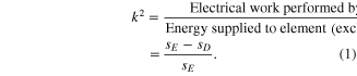
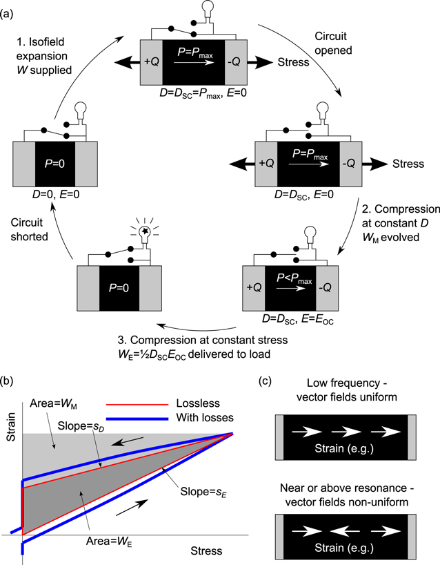
Figure 1. (a) Illustration of three-step off-resonance vibrational energy harvesting cycle. Operations which involve conversion of energy are regarded as 'steps'. (b) Equivalent strain versus stress diagram of the cycle shown in (a). The thin (red) line illustrates a lossless cycle while the thick (blue) line illustrates a lossy cycle. (c) Schematic showing how stress and strain fields become non-uniform near and above resonance frequencies thereby reducing overall electromechanical coupling at these frequencies.
Download figure:
Standard image High-resolution imageThis definition of k2 explicitly excludes any losses due to plastic flow and non-zero electrical conductivity of the element. The definition also excludes the mechanical work performed by the element during isodisplacive compression, some or all of which could in principle be usefully recovered. Taking these into account, we separately define energy conversion efficiency χ as:

Thus, χ could be either less than k2 if losses are present, or greater than k2 if mechanical work during isodisplacive compression is recovered. The latter occurs when the VEH cycle is operated at mechanical resonance of the piezoelectric element and can thus lead to higher NG efficiencies. Figure 2 illustrates all aspects of the conversion of energy by the NG. In effect, at resonance, a significant proportion of the mechanical work from one VEH cycle is recovered (WR), and then supplied back to the system during the subsequent cycle. Thus, for a driven system, the amount of externally-supplied energy required to maintain the system oscillating is reduced. The converse is true at frequencies below resonance where most of the mechanical energy is wasted (WW). An important point is that a piezoelectric element driven with a sinusoidal stress shows essentially equivalent energy conversion efficiency to the three-step cycle provided load resistor R is impedance matched to the piezoelectric capacitor C, via R = ω/C (see supplementary information for a full discussion).
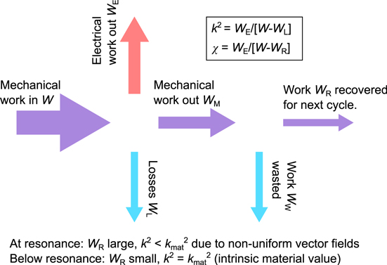
Figure 2. Schematic representation of the energy conversion process in a piezoelectric nanogenerator.
Download figure:
Standard image High-resolution imageIn the case of piezoelectric nanowires, at high frequencies close to resonance, standing waves are established within the nanowires resulting in non-uniform T, S, D and E. This situation (figure 1(c)) is treated by defining an effective electromechanical coupling factor, k2eff, whose value is reduced from the low-frequency 'material' value, k2mat [43, 44]. It should be noted that at a sufficiently localized level, such that the vector fields S, T, P and E are uniform, the intrinsic electromechanical coupling of the material defined by stored electrical energy divided by stored total energy, is always k2mat. The dynamic k2eff is exclusively a result of non-uniformity of the vector fields on a macroscopic scale. The properties of piezoelectric resonators are usually treated by modeling the mechanical components of the system as equivalent electrical components, and employing electrical network theory [44, 45].
NG driving scenarios
In order to make a qualitative comparison between the behavior of TNGs, SNGs and INGs, we consider the form of the frequency-dependent strain response function in each case. For SNGs the strain is fixed via the external driving mechanism, whereas for TNGs and INGs it is specified by the differential equations of motion as described in supplementary information. For a lossless NG with impedance-matched load resistor, figures 3(a)–(c) show the strain amplitude S0 as a function of NG driving frequency for illustrative values of T0 = 200 MPa (TNG), S0 = 0.2% (SNG) and y0 = 0.1 μm (ING) respectively, for a NG with L = 50 μm, ρ = 5000 kg m−3, ωn = 90 MHz, and k2 = 0.25, 0.5 and 0.75 (parameters similar to PbZrxTi1-xO3). For illustration purposes we assume k2 remains constant as a function of ω. This holds true in the range of practical interest far below resonance and in practice k2 is reduced by typically only a few tens of percent at the first harmonic [44]. Figure 3 shows that while there is negligible strain response of the ING at low frequencies, the strain response of the TNG and the SNG are invariant of frequency in this range. At resonance, the ING exhibits a sharp peak in its response function, the TNG shows a slightly enhanced response function due to kinetic-mediated recovery of mechanical energy, while the SNG shows a constant response at all frequencies near and away from resonance. In general, SNGs can be realized with vibrational sources that are much larger than the NG itself, such that the loading effect of the VEH mechanism on the vibrational source is negligible.
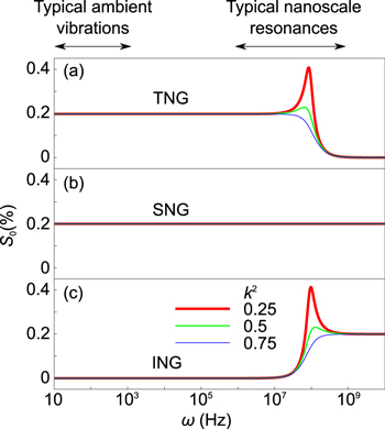
Figure 3. Frequency-dependent strain response plotted for a lossless piezoelectric nanogenerator under (a) strain-driven, (b) stress-driven, and (c) inertial conditions, respectively.
Download figure:
Standard image High-resolution imageFor a material such as PbZrxTi1-xO3 in which k2 may take values as high as ∼0.5 [43], half of the total work done by the element is performed, usefully or otherwise, on the electrical load and thus not available for mechanical recovery. The VEH process will itself impose large levels of damping which ensures that χ remains large at low frequencies with only a modest enhancement at resonance. In contrast, the penalty to χ below resonance may be severe for materials with small values of k2, as this results in a large amount of mechanical energy WM which is unrecoverable below resonance (figure 2). A particularly notable example of this is the study of Wang and Song on nanowires of ZnO [3], a material with a relatively small intrinsic value of k2 = [d2/sE] ∼ 0.06 (using the values for sE, piezoelectric charge coefficient d, and dielectric permittivity given in [3]). Some literature values for k2 for bulk ZnO are higher, at 0.17 [43]. The quoted efficiency of 19–30% [3] of the nanowires was evaluated assuming 100% of the available mechanical energy was recovered for subsequent oscillations, thus such efficiencies would only be realizable at the resonance frequency of ∼0.7 MHz [46]. The efficiency below this frequency is found to be 165 times smaller, at 0.13% as may be deduced from the supplementary information of [3].
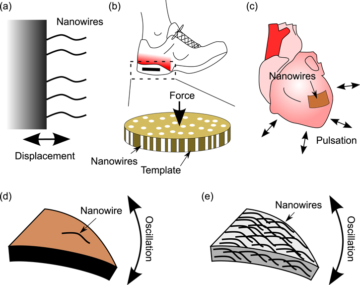
We now consider specific NG geometries and categorize the respective mechanical excitation modes, as illustrated in figure 4. Figure 4(a) shows piezoelectric nanowires attached directly to a large vibrating structure, akin to vibrating nanoscale cantilevers. This system represents an ING with a resonance frequency of the order of tens of MHz, far above the likely range of vibrations of the structure (sub-kHz). The harvested power in this ambient vibration frequency range would be negligible (figure 3(c)). Figure 4(b) shows a NG comprising an array of piezoelectric nanowires in a template [1], implanted in a running shoe thereby subjected to a periodic impacting force. If the area-weighted stiffness of the template is large compared to that of the nanowires, as in the case for the NG reported in [1], then the displacements of the nanowires are fixed by the elastic response of the template to the applied force. This system represents a SNG whose harvested power is not frequency-dependent (figure 3(b)) and is thus a good candidate for ambient VEH. In the contrary limit where the area-weighted stiffness of the template is small compared to that of the nanowires, the nanowires elastically respond to the applied force with negligible contribution from the template. This system represents a TNG whose harvested power peaks at the resonance frequency of the nanowires, but remains finite at low frequencies (figure 3(a)) and is thus also a viable candidate for ambient VEH. A spectrum of VEH performance can be thought to exist between these two extremes. Figure 4(c) shows nanowires on a flexible substrate arranged to envelop a pulsating organ, as in the case for the NG reported in [19]. The displacement of the nanowires in response to the mechanical excitation is fixed in this case and thus this system represents a SNG, provided it imposes a negligible mechanical load on the organ (as would be a prerequisite for such an application). Similar arguments might apply to NGs embedded in close-fitting clothing. Figure 4(d) shows the case of a single nanowire attached to a larger resonating cantilever as another example of a SNG, as in the case for the NG reported in [2]. This scenario can also be extended to a NG comprising multiple nanowires on a flexible substrate [18, 21] as long as the mass of the nanowires is negligible in comparison to the substrate such that it is not loaded by the VEH mechanism. In this case, while the harvested power does not depend on the resonance frequency of the constituent nanowires, it can be maximized by operating close to the resonance frequency of the cantilever itself which is expectedly far lower due to its size. A similar effect is exploited in the low-frequency NG reported in [16] where the resonance frequency of a large vibrating electrode is exploited, rather than the inherent high resonance frequency of the ultra-long BaTiO3 nanowires themselves. Finally, we consider a large resonating cantilever comprising a large number of embedded piezoelectric nanowires (figure 4(e)), in the form of a composite system, whereby the mass of the nanowires is significant. This is an interesting and important system because the elastic properties of the nanowires clearly influence those of the cantilever, yet each individual nanowire is under strain-driven conditions when the composite cantilever is subjected to mechanical excitation, as with the previous case shown in figure 4(d). The response function of each individual nanowire is therefore frequency-invariant, but the strain applied to the nanowires is governed by the response function of the large composite cantilever which in itself is an example of ING, whose elastic and damping properties are synonymous with those of the constituent nanowires. In other words, composites of piezoelectric nanowires combine the favorable electromechanical coupling properties of the nanowires with the favorable resonance properties of the macroscopic composite, even though individually the nanowires have unfavorable resonance frequencies. The overall energy conversion efficiency of the composite cantilever is determined by the intrinsic low-frequency efficiency χ of the nanowires, with an enhancement associated with mechanical energy recovery in the resonating macroscopic cantilever structure. Furthermore the degradation of electromechanical coupling associated with resonance due to non-uniformity of the vector fields on a macroscopic scale, as explained previously, is eliminated as the nanowires are in a strain-driven state at frequencies far below their intrinsic resonance. Recently demonstrated nanocomposite-based NGs [47, 48] may also be modeled along similar lines.
Figure 4. Examples of piezoelectric nanowires incorporated into nanogenerators under different loading conditions.
Download figure:
Standard image High-resolution image
Polymers versus ceramics
In order to make a fair comparison of materials for specific NG applications, one should normalize electrical output by the applied excitation. The electrical output WE of an NG is given by χW, which evaluates to ½χS2/sE for SNGs and ½χT2sE for TNGs. We therefore define figures of merit as ηS = χ/sE and ηT = χsE for SNGs and TNGs respectively, by normalizing WE per unit squared strain and per unit squared stress in the respective cases. For INGs, one should normalize WE per unit squared oscillation amplitude. For INGs specifically with some composite structure as depicted in figure 4(e), the Williams and Yates model may be applied for a normalized expression for harvested power P [41]. We now compare, in table 1, the VEH performance of some of the most commonly reported ceramic and polymer NGs in the literature, namely ZnO, Pb(Zr0.52Ti0.48)O3 (PZT), 0.72Pb(Mg1/3Nb2/3)O3-0.28 PbTiO3 (PMN-PT), PVDF and poly(vinylidene fluoride-trifluoroethylene) (P(VDF-TrFE)). In order to evaluate the relevant low-frequency χ (equation 2), the electrostatic energy at the end of step 2 of the three-step cycle (figure 1(a)) must be evaluated as ½EOCDSC = ½TEOC2 = ½DSC/T (where T is the dielectric permittivity at constant stress), and the input mechanical energy must be evaluated as ½ST = ½sET2 = ½S2/sE. A direct measurement of χ thus requires EOC, DSC, T and S to be measured independently, including components corresponding to energetic losses. In practice EOC and short-circuit current ISC (from which DSC can be estimated by integration) are reported, but S or T (depending on the mode of mechanical excitation) are rarely reported. Furthermore dielectric and elastic loss tangents are seldom considered in NG literature. A variety of mechanisms can lead to parasitic energy losses in piezoelectric NGs, such as leakage conductivity and plastic flow. In general, losses are liable to vary with respect to frequency and any applied bias field or stress. To quantify both electrical and mechanical losses together, the loss tangent should be evaluated from the phase lag between an applied E and resulting D at constant T (conditions of constant S would correspond to electrical losses alone). Neglecting losses, T (and hence S) can be evaluated as EOC/g33 or DSC/d33, where g33 and d33 are the piezoelectric voltage and current coefficients respectively. Where nanoscale measurements of these piezoelectric coefficients are unavailable, T may be estimated using bulk values of g33 instead of bulk values of d33, as there is less variation in g33 across materials and geometry [43]. As T can be readily evaluated for a specific NG as DSC/EOC, d33 may be obtained from the electrical data as Tg33. Measurements of piezoelectric and elastic coefficients for nanoscale geometries are possible [18] and would, along with measurements of losses, yield more reliable values of χ than have been shown in table 1.
Table 1.
Comparison of NG performance of piezoelectric ceramic and polymer nanowires under strain-driven and stress-driven conditions. Three different ceramics (ZnO, †Pb(Zr0.52Ti0.48)O3 and ‡0.72Pb(Mg1/3Nb2/3)O3-0.28PbTiO3) and two different polymer NGs (PVDF and P(VDF-TrFE) 70/30 mol%) with different geometries and loading conditions are considered. Figures of merit normalized by applied squared strain and applied squared stress are given by  and
and  respectively. Entries with an asterisk denote bulk measurements in the absense of bespoke measurements at the nanoscale.
| Ceramics | Polymers | |||||
|---|---|---|---|---|---|---|
| Material | ZnO [4] | ZnO [6] | PZT† [21] | PMN-PT‡ [27] | PVDF [2] | P(VDF-TrFE) [1] |
| Device length L (μm) | 200 | 10 | 5 | 150 | 100–600 | 60 |
| Diameter t (nm) | 4000 | ∼100 | 500 | 200–800 | 600–6500 | 200 |
| Device area A (mm2) | N/A | 225 | 6 | 50 | N/A | 157 |
| |g33| (V Pa−1) | 0.1 [7] | 0.1 | 0.036 | 0.039* [53] | 0.17* [54] | 0.43* [54] |
| sE (TPa−1) | 25 | 34.5 [3] | 23 [52] | 86* [53] | 714 | 400* |
| /0 |
10* [43] | 10* [43] | 470* [23] | 6833* [53] | 16* [54] | 10.9* [54] |
| Mode of excitation | Flex | Impact | Impact | Impact | Flex | Impact |
| VOC (V) | 0.035 | 35 | 0.7 | 6 | 0.01 | 3 |
| DSC (μC m−2) | N/A | 440 | 920 | 500 | N/A | N/A |
| WE | 0.65 pJ a | 0.77 kJ m−3 b | 64 J m−3 b | 13.3 J m−3 b | 0.4 pJ a | 0.3 J m−3 a |
| W | 12.5 pJ c | 15.5 kJ m−3 d | 350 J m−3 d | 85 J m−3 d | 3.2 pJ c | 2.7 J m−3 d |
| Nominal χ (%) | 5.2 | 5 | 18 | 16 | 12.5 | 11 |
| ηS (GJ m−3) | 2 | 1.5 | 7.8 | 1.8 | 0.18 | 0.27 |
| ηT (pJ m−3 Pa−2) | 1.3 | 1.7 | 4.1 | 13.8 | 89 | 44 |
aWE is evaluated by integrating electrical power IV with respect to time. bWE is evaluated as ½EOCDSC, where EOC = VOC/L and DSC = Q/A is derived by integrating short-circuit current with respect to time. cStrain S is measured directly. dStress T is obtained from one or both of the piezoelectric charge and voltage constants, via T = DSC/d33 and T = EOC/g33. W is evaluated as ½sET2.
It can be seen from table 1 that while both piezoelectric ceramic and polymer nanowires have been reported to exhibit similar order-of-magnitude values of χ, they are found to exhibit significant difference in values of ηS and ηT due to their different elastic properties. Ceramics such as ZnO, PZT and PMN-PT are found to have larger values of ηS and are thus more suitable for applications in SNGs, while polymer nanowires are found to have larger values of ηT and are thus more suitable for applications in TNGs. It should be noted, however, that plastic and electric degradation imposes a maximum operating strain which would tend to be smaller for ceramic materials with further implications for fatigue characteristics, although some improvement in this may be expected at the nanoscale [49]. Furthermore, the absence of quantitative information on losses in the literature is an issue that needs to be addressed for a better understanding of the energy conversion process [50].
Discussion
VEH using piezoelectric NGs has progressed a great deal since the pioneering work of Wang and Song in 2006 on ZnO nanowires, [3] with advances and innovations in materials and device fabrication techniques. To date, the experimental research of NGs has focused on demonstrating the working mechanism and potential devices and applications. While there has been a steady increase in the number of NGs reported over the last few years [51], a balanced and rational quantitative analysis of NG performance has been notably absent. NG output data are often presented without normalization with respect to geometry and/or applied stress/strain, and thermodynamically relevant parameters required to evaluate electrical work are often unreported. For example, in a VEH cycle, the output charge determines electrical work extracted per cycle, and not the short-circuit current. However, NG output charge is rarely measured appropriately (e.g. using a Sawyer Tower circuit), and furthermore, measurements of short-circuit current are often insufficiently dense to extract charge by integration, rendering a fair quantitative evaluation of electrical work impossible (see supplementary information 2). This could be trivially mitigated by controlling strain rates to spread out the flow of charge temporally. In cases where we have been able to extract output charge from output current data, T evaluated as DSC/EOC often took unphysical values, implying that the data and/or geometric normalization could have been compromised (see supplementary information 2 for case studies). One of the aims of the present work is thus to highlight the importance of adequate reporting and verification of all thermodynamically pertinent quantities to allow for the evaluation of NG materials figures of merit. While the demonstration of the capabilities of NGs to power devices such as light emitting diodes [25], liquid crystal displays [17], and the nervous systems of small amphibians [7] are certainly noteworthy, they are limited to qualitative representations of NG performance, whereas 'efficiency' should be quantitatively determined for meaningful comparison of NG performance.
Conclusions
In summary, we have introduced NG figures of merit defined as energy harvested normalized by applied strain or stress for NGs under strain-driven or stress-driven conditions respectively, in order to compare the VEH performance of piezoelectric ceramic and polymer nanowires. These NG figures of merit take into account the device geometry and driving mechanism and thus indicate which materials are likely to perform well in specific VEH applications. The values of ηS and ηT that we present here reveal that stiff ceramic nanowires are likely to perform better in SNGs while flexible polymer nanowires are likely to perform better in TNGs. It should be recognized that from the point of view of device engineering, a variety of other factors come into play such as flexural modes, fatigue characteristics, limits of mechanical deformation, and operating temperature range. However, ηS and ηT represent a useful and general starting point for identification of suitable materials for stress-driven and strain-driven applications. We have also demonstrated that the intrinsic high resonance frequencies of piezoelectric nanowires present no significant barrier to the VEH performance of NGs comprised on these nanowires in purely strain-driven or stress-driven scenarios. We have shown that composites comprising nanowires forms a special case of INGs where the favorable low-frequency electromechanical coupling properties of the nanowires are harnessed in a resonance-based harvester. Our work could in future be used to compare piezoelectric materials for use in nanowire-based NGs so that the energy conversion efficiency of materials underpinning novel VEH technologies can be quantitatively compared.
Acknowledgments
We thank Chris Bowen, Xavier Moya and Richard Whiter for critical feedback on the manuscript. SKN is grateful for financial support from the Royal Society through a Dorothy Hodgkin fellowship, and from the European Research Council through an ERC starting grant (grant no. ERC-2014-STG-639526, NANOGEN).