

Abstract
Bulk metallic glasses (BMGs) are ideal for nanomoulding as they possess desirable strength for molds as well as for moldable materials and furthermore lack intrinsic size limitations. Despite their attractiveness, only recently Pt-based BMGs have been successfully molded into pores ranging 10–100 nm (Kumar et al 2009 Nature 457 868–72). Here, we introduce a quantitative theory, which reveals previous challenges in filling nanosized pores. This theory considers, in addition to a viscous and a capillary term, also oxidation, which becomes increasingly more important on smaller length scales. Based on this theory we construct a nanomoulding processing map for BMG, which reveals the limiting factors for BMG nanomoulding. Based on the quantitative prediction of the processing map, we introduce a strategy to reduce the capillary effect through a wetting layer, which allows us to mold non-noble BMGs below 1 μm in air. An additional benefit of this strategy is that it drastically facilitates demoulding, one of the main challenges of nanomoulding in general.
Export citation and abstract BibTeX RIS
1. Introduction
A critical requirement for any moldable material is that its intrinsic length scale is small compared to the size of the mold's features. Polymers are ultimately limited by their chain lengths and crystalline materials are limited by their grain sizes. Bulk metallic glasses (BMGs) lack intrinsic size limitation on the nanoscale [1–5]. In addition to this crucial attribute, BMGs are hard and tough compared to other materials used for nanomoulding, yet they can be softened into a state in which they can be readily molded [2]. These properties are often combined with favorable chemistry for biocompatibility, electrochemical activity, antibacterial behavior, and biodegradability.
Despite their attractiveness, until recently, BMGs could not be molded into features below 100 nm. Kumar et al [1] was first to mold Pt57.5Cu14.7Ni5.3P22.5 into pores of 10–100 nm in diameter and lengths that correspond to an aspect ratio of over 20. The ability to mold BMGs in a controllable manner has triggered broad research in exploring applications, such as electrochemical catalysts [6–9], micro fuel cell [10], MEMS/NEMS [5, 11, 12], programmable biomaterials [13–15] and wastewater treatment materials [16, 17]. Besides these applications, molded BMG nanostructures have also enabled the scientific community to study size and confinement effects on mechanical properties [18–25], deformation modes [26–29], crystallization [30, 31] and flow behaviors [23]. However, Kumar's findings and all following BMG nanomoulding has been limited to very few, noble-metals-based alloys such as Pt57.5Cu14.7Ni5.3P22.5 [1] and Pd43Ni10Cu27P20 [32–34] with a high resistance to oxide formation. Enabling the broad potential applications of BMG nanomoulding requires the development of nanomoulding strategies for more economic BMGs. Most BMGs, however, readily oxidize, particularly when heated into the supercooled liquid region (SCLR) like during thermoplastic forming (TPF) [35]. Such oxidizing results in the formation of a rigid oxide layer which dramatically affects and ultimately prohibits the TPF filling of nanosized pores for the vast majority of BMGs. We show here a general description for quantitative prediction of molding of BMGs into nanoscale features, which accounts for possible oxide formation. Our model includes a threshold pressure and a capillary contribution, which are required to break the oxide film and overcome the capillary force to enter into a nanopore, respectively. In addition, a viscous term, which when compared to the strength of the mold, defines the possible moldable aspect ratios. Based on this quantitative model which we use to construct a nanomoulding processing map for Zr35Ti30Cu8.25Be26.75, we introduce a strategy to reduce the capillary effect, which allows us to fabricate nanorods in air from highly reactive, non-noble based BMGs such as Zr35Ti30Cu8.25Be26.75, Zr44Ti11Cu10Ni10Be25 and Mg65Cu25Y10.
2. Materials and methods
The nanomoulding experiments are operated in air with a heating-cell equipped Instron 5569 machine (50 kN maximum load capacity). The processing temperature for Zr35Ti30Cu8.25Be26.75, Zr44Ti11Cu10Ni10Be25 and Mg65Cu25Y10 with/without oils is 435 °C and 175 °C, respectively. The total processing time for all of the samples is ∼2 min and the maximum loading force is 50 KN. Demoulding of Zr35Ti30Cu8.25Be26.75 and Zr44Ti11Cu10Ni10Be25 nanorods is achieved through etching Al2O3 templates with KOH solution (3 mol L−1, temperature of 85 °C). For Mg65Cu25Y10, we use H3PO4 solution (concentration of ∼85%, temperature of 85 °C) due to the high reactivity of the alloy with both alkaline and acidic solutions.
To demonstrate the use of BMGs as molds and moldable materials, we choose as an example Pt57.5Cu14.7Ni5.3P22.5 as a moldable material and Pd43Ni10Cu27P20 as a mold material. Firstly, a Pd43Ni10Cu27P20 BMG disc is thermoplastically formed into a nanoporous Al2O3 template at 360 °C. The maximum loading force and processing time are 5 KN and 2 min, respectively. Pd43Ni10Cu27P20 nanorods arrays to be used subsequently as a mold are exposed by etching the Al2O3 template. We then place a Pt57.5Cu14.7Ni5.3P22.5 disc which is covered by a thin layer of high temperature oil on the Pd43Ni10Cu27P20 nanorods array mold and thermoplastically form the mold-replicate combination at 270 °C. Demoulding is realized by a small mechanical force applied at room temperature.
3. Processing map for BMG nanomoulding
Thermoplastic compression molding, a process in which moldable material is heated to flow into micro/nanopore under an applied pressure, has been widely used in surface patterning for polymers [36–39] and BMGs [3, 12, 40–45] due to its simplicity and scalability. Typically for a cylindrical pore with diameter, d, the required pressure to drive a liquid into a pore, p, can be calculated from Hagen–Poiseuille law

where η is the liquid's viscosity and  is the maximum shear strain rate.
  is located at the liquid-mold interface when assuming a parabolic velocity distribution. This flow resistance linearly scales with the viscosity of the liquid (figure 1(a)). Typically for creep flow of BMGs in their SCLRs,
  and their minimum accessible viscosity can vary significantly among BMG formers ranging 105–109 Pa s [46]. For η > 109 Pa s, the molding pressure of 10 GPa is prohibitively high to fill an aspect ratio of three. Figure 1(a) and equation (1) also suggest that the viscous resistance of BMG liquids is size independent, which has been experimentally confirmed for molds larger than approximately one micron [47]. However, for nanosized molds, <100 nm, experiments revealed a size dependent forming pressure [1]. Kumar et al introduced a capillary effect to the viscous term into equation (1) to account for the size dependence [1]. The total pressure is then

Here θ is the contact angle between BMG liquid and mold, and γ is the surface energy of BMG liquids. The capillary term (second term in equation (2)) is independent of L and inversely proportional to the diameter (figure 1(b)). Hence, the capillary term is independent of the aspect ratio and therefore sets the lower boundary for hydrophobic molds. For an applied pressure below p = −4γ*cos θ/d, nanorods cannot be molded.
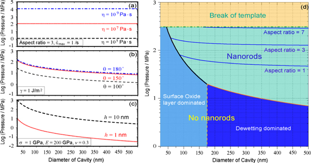
Figure 1. Thermoplastic based nanomoulding of bulk metallic glasses. (a) Contribution of the viscosity term to the forming pressure for BMG liquids flowing into a nanopore (equation (1)) for an aspect ratio of three, and a maximum shear strain rate of  max ∼ 1 s−1. (b) For nanosized molds, the capillary effect should be included in the pressure (second term in equation (2)) which inversely linearly scales with the diameter of a pore. (c) When nanomoulding supercooled BMGs in air, the BMG surface is typically covered with an oxide layer, which deforms as a rigid film under normal pressure exerted by the BMG liquid. The pressure needed to break the oxide layer scales with the square of the diameter of a nanopore. (d) Processing map for Zr35Ti30Cu8.25Be26.75 which is constructed based on (a)–(c), with
  max ∼ 1 s−1, η = 107 Pa s, θ = 150°, γ = 1 J m−2, and h = 10 nm. The molding pressure is limited by the strength of the mold, approximately 300 MPa [49] for Al2O3 template assuming a 0.2% elastic limit. Formation of nanorods is initially limited by the pressure requirement to break the oxide layer (black line) and/or overcome capillary force (red line), which are the onset boundaries of nanomoulding.
Download figure:
Standard image High-resolution imageHowever, equation (2) does not consider that most BMG surfaces, in their supercooled state, are covered with an oxide layer, especially when molded in air [35]. The formation and thickness of such a rigid oxide layer increases with the reactivity of the BMG alloys. In order to mold the BMG into nanosized pores, this rigid oxide layer must break to allow BMG liquid to flow into the pores. Up to now, reactive BMGs like Zr-based BMGs have never been molded into pores below 1 μm, suggesting that the molding barrier from the oxide layer may be dominant on the nanoscale. In order to quantify this effect we modeled the surface oxide film by the Karman's nonlinear equations (in cylindrical coordinate system)


where E is the elastic modulus,  is flexural rigidity and v is Poisson ratio, w is the normal displacement, Nr is the total membrane stress, and p is the uniform pressure exerted by the supercooled BMG liquid. Based on a dimensionless analysis, the pressure (p0) to break this surface oxide layer should be of the form of

where σc is the strength of the oxide layer, and h the thickness of the oxide layer. From linear theory of small deflection and von-Mises yielding criterion, equation (5) can be written as

which defines the pressure to break the oxide layer. This pressure barrier scales with (1/d)2 and is more dramatic than the linear-scaling entering barrier from surface dewetting (second term in equation (2)). This scaling behavior reveals that the oxide layer barrier is indeed dominating the filling requirements of small pores. Considering the nonlinear effect, the more accurate pressure to break the oxide layer (p0/E) is related to the maximum deflection value (wm/h) when first yielding at clamped edges [48]

where  By substituting the mechanical properties of the oxide layer (E ∼ 200 GPa, σc ∼ 1 GPa, and v ∼ 0.3) and the oxide thickness (1 and 10 nm) into equation (7), the maximum deflection value (wm/h) at yielding is calculated. Then substituting this value into equation (8), the critic pressure p0 to rupture the oxide layer is finally obtained (figure 1(c)). It is obvious that when molding into small pores, the surface oxide layer becomes increasingly important. However, this is only the case for reactive alloys such as Zr-BMGs. For alloys with high corrosion resistance such as Pt-BMGs, the contribution of an oxide layer can be neglected.
The maximum aspect ratio that can be achieved in molding nanorods is ultimately limited by the strength of the mold (σ0), which defines the upper bound for the applied pressure. As a consequence, the maximum aspect ratio that can be realized is given by

Equations (2), (7), (8) and (9) describe the general nanomoulding of supercooled BMGs (figures 1(a)–(c)). This description can be used to construct a BMG's processing map, which reveals the dominating effect of nanomoulding at different pore diameters. Taking Zr35Ti30Cu8.25Be26.75 for example, parameters are  η = 107 Pa s, θ = 150°, γ = 1 J m−2. Furthermore, we assume a maximum strength of σ0 = 300 MPa for Al2O3 template (with 200 nm diameter pores) from a 0.2% elastic limit [49]. Combining equations (2), (3), and (5), the processing map can be constructed (figure 1(d)), where the oxide thickness is set as h = 10 nm, the upper bound in our experiments. We measure such a thickness of the oxide layer by oxidizing Zr35Ti30Cu8.25Be26.75 thin plate at 435 °C for 4 min in air. Subsequently, the plate is stretched to break the surface oxide layer and the thickness is determined using SEM (figure 5).
4. Results and discussions
4.1. Nanomoulding non-noble BMGs by adding a wetting layer
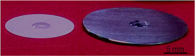
The processing map (figure 1(d)) reveals the dominating effects controlling molding into different size pores. Prior to this work, Zr-BMGs have not been molded into features smaller than 1 μm. For this size region, the processing map reveals that the dominating barrier originates from either the capillary effect or surface oxide. To reduce these barriers, and hence enable nanomoulding with non-noble BMGs, we propose a simple strategy through introducing a wetting layer to the Al2O3 template surface (figure 2(a)). Specifically, we immerse Al2O3 templates and/or BMGs into high temperature oil prior to the molding operation. Oils typically wet ceramics and metals. We choose DuPont Kryto oil which wets Al2O3 template and Zr35Ti30Cu8.25Be26.75 well (contact angle θ < 45°, figure 6). By reducing the surface energy through the surface wetting oil, we successfully mold Zr35Ti30Cu8.25Be26.75 and Zr44Ti11Cu10Ni10Be25 into 100 nm nanopores. One of the results for 200 nm nanorods with aspect ratio over five is shown in figure 2(d). In contrast, molding under the same processing conditions but without oil does not result in any filling of the 200 nm pores (figure 2(c)).

Figure 2. (a) Molding reactive BMGs by reducing capillary force through the use of an interlayer wetting layer. Al2O3 templates are coated with high temperature oil (DuPont Kryto) prior to the molding operation. (b) After thermoplastic forming Zr35Ti30Cu8.25Be26.75 into a 200 nm Al2O3 template at 435 °C for ∼2 min. Left: without the use of a wetting layer, right: with the use of high temperature oil as a wetting layer. (c) Nanorods do not form without oil. (d) Formation of nanorods under the same conditions as (c) but with oil.
Download figure:
Standard image High-resolution imageWe attribute the successful nanomoulding of Zr-BMG when using an oil layer to the reduced surface energy of BMG liquids which decreases the capillary (second term in equation (2)). When forming supercooled Zr35Ti30Cu8.25Be26.75 into a nanopore wetted with oil, the capillary term in equation (2) changes to  and the interfacial tension between oil and supercooled BMG can be estimated by
  [50]. The capillary term thus becomes
  which suggests that the capillary effect can be reduced by using oil. In addition, the changing of sticky boundary to lubrication boundary may help to reduce the flowing resistance and thus enable the fabrication of nanorods with larger aspect ratio, which is still under investigation.
To demonstrate the general applicability of this strategy, we also mold Zr44Ti11Cu10Ni10Be25 and Mg65Cu25Y10 into pores of 200 nm in diameter (figure 3). When applying an oil film, both alloys can be nanomolded. The appearance of the Mg65Cu25Y10 nanorods is affected by the subsequent H3PO4 etching to remove the Al2O3 template.
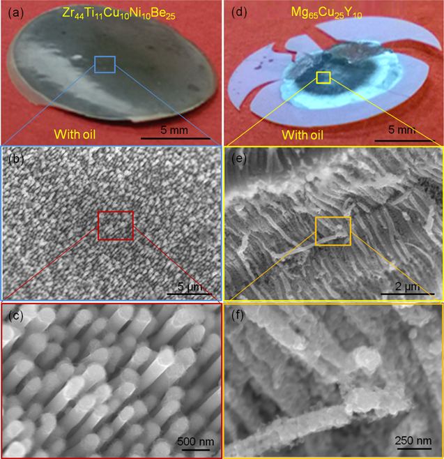
Figure 3. Nanomoulding Zr44Ti11Cu10Ni10Be25 and Mg65Cu25Y10 by using oil-wetted Al2O3 templates. Zr44Ti11Cu10Ni10Be25 and Mg65Cu25Y10 are molded at 435 °C and 175 °C, respectively. The total processing time is ∼2 min and the maximum loading force is 50 KN. (a) and (d) show the as-thermoplastic formed samples. The dark color in both of the BMGs suggests that nanorods formed. (b)–(c) SEM images of Zr44Ti11Cu10Ni10Be25 nanorods after removing the Al2O3 template through KOH etching. (e)–(f) Mg65Cu25Y10 nanorods with Al2O3 template partially etched by using H3PO4. The reactivity of Mg65Cu25Y10 with both alkaline and acidic solutions which are required to etch the Al2O3 template causes degradation of the nanorods.
Download figure:
Standard image High-resolution image4.2. BMGs used as molds and moldable materials
Besides using BMGs as ideal moldable materials, BMGs' drastic temperature dependent strength can also be utilized as a means to use them as molds. For example the softening temperatures of thermoplastics are usually below 200 °C, which is lower than the glass transition temperatures (Tg) for most BMGs. Hence, BMGs are high strength at these temperatures, hence can be used as molds for thermoplastic polymers. Due to the large range of glass transition temperatures among BMGs, nanomoulding one BMG with another BMG mold is also possible. The selection of the appropriate BMGs depends on their relative glass transition temperatures. This attribute and requirement are schematically shown in figure 4(a), where the viscosity (or flow stress) of BMGs can decrease by several orders of magnitude when the temperature approaches Tg. Compared with other mold materials such as silicon and Al2O3 molds, BMG nanomolds are advantageous due to their high elasticity, strength, and toughness. These attributes warrant long mold life, ability to demould, and precise and inexpensive fabrication of the mold.

Figure 4. BMGs used as mold or moldable materials. (a) Requirements for a BMG mold/moldable material combination are that one BMG has sufficiently softened, which is achieved by processing in its supercooled liquid region close to its crystallization temperature. The other BMG to be used as a mold should have a 20% higher Tg than that of the moldable BMG. Such a difference guarantees several orders of magnitude difference in strength (flow stress). (b) Schematics of nanomoulding Pt-BMG using Pd-BMG nanorods as a mold. (c)–(d) Pd43Ni10Cu27P20 nanorods after demoulding from Pt57.5Cu14.7Ni5.3P22.5. (e)–(f) Replicated nanoholes in Pt57.5Cu14.7Ni5.3P22.5.
Download figure:
Standard image High-resolution imageTo demonstrate this concept, Pd43Ni10Cu27P20 nanorod arrays of 200 nm in diameter are fabricated by replicating Al2O3 mold at 360 °C. Subsequently, these nanorod arrays act as a mold and are replicated at 270 °C with oil-wetted Pt57.5Cu14.7Ni5.3P22.5. Demoulding at room temperature can be readily achieved by small mechanical forces. This method, in contrast to all previous BMG nanomoulding methods, allows the reuse of the mold. As such it represents a step towards commercial usage of BMG nanostructures since it drastically reduces fabrication costs which in the past included the disposable Al2O3 template.
5. Conclusions
We identified the governing contributions for most general BMG nanomoulding. These are viscous, capillary, and surface oxide layer fracture. The viscous contribution dominates for supercooled BMGs with large viscosity, when filled into high aspect ratios. The capillary term scales with the characteristic dimension of the nanopore and is determined by interface wetting properties (surface energy/contact angle). The surface oxide layer controls the filling barrier at smaller scales since it scales with the square of the diameter of the nanopore. Our general description allows for quantitative predictions, which can be used to create a processing map for BMG nanomoulding.
The processing map reveals the limiting factors, which have prevented nanomoulding for the majority of BMG alloys in the past. We used this knowledge to develop a molding strategy using a wetting layer to reduce the entering barriers. Using this method, reactive BMGs based on Zr and Mg can be nanomolded under practical conditions. Furthermore, the wetting layer also dramatically reduces interfacial forces, which suggest the possibility for a non-disposable mold method for BMG nanomoulding.
Acknowledgment
This work was primarily supported by the National Science Foundation under MRSEC DMR-1119826. Facilities use was supported by YINQE. We thank Dr Sungwoo for help casting Mg-BMG.
Appendix
A.1. Oxidation rates
We oxidized Zr35Ti30Cu8.25Be26.75 in air at 435 °C and subsequently stretched the BMG to break its surface oxide layer. The total processing time is ∼4 min. The ruptured surface oxide layer is clearly revealed under an optical microscope (figure 5(a)). Using SEM (figures 5(b)–(c), the sample stage is tilted 30°), the oxide thickness is measured to ∼156 nm, which corresponds to a 0.65 nm s−1 oxidation rate if assuming a linear oxidation. During the TPF-based molding, we usually consume ∼15 s to reach the processing temperature, which defines the upper bound thickness of the oxide layer to ∼10 nm (0.65*15 nm).

Figure 5. Surface oxide layer on Zr35Ti30Cu8.25Be26.75, formed during processing in air at 435 °C. Subsequently the sample is deformed to rupture the surface oxide, resulting in a total processing time of 4 min. (a) Optical microscopy image reveals the rupture of the surface oxide layer. (b)–(c) By using SEM (the sample stage is tilted 30 degrees), the oxide thickness is measured to about 156 nm, which corresponds to an oxidation rate of 0.65 nm s−1 by assuming a linear oxidation process. Within our processing protocol, it takes ∼15 s to heat the sample, which gives the upper bound thickness of the oxide layer to 0.65*15 nm ∼10 nm.
Download figure:
Standard image High-resolution imageA.2. Wetting properties of high temperature oil with templates and BMGs
The contact angles of oil drops on surfaces of Al2O3 and polished Zr35Ti30Cu8.25Be26.75 are smaller than 45° (figure 6), which suggests the high temperature oil (DuPont Kryto) used in our experiments wet both of them well.
Figure 6. Wetting of high temperature oil (DuPont Kryto) on Al2O3 template and polished Zr35Ti30Cu8.25Be26.75.
Download figure:
Standard image High-resolution image