
Abstract
We report experimental results on the effects of laser contrast on beam divergence and energy spectrum of protons emitted from ultrashort intense laser interactions with normal large foils and transverse-size-reduced targets. Correlations between beam divergence and spectral shape are found. Large divergence and near-plateau shape energy spectrum are observed for both types of targets when the laser pulse contrast is low. With high contrast laser irradiation, proton beam divergence is remarkably reduced and the energy spectral shape is changed to exponential for large foil targets. In comparison, a similar large divergence and the near-plateau spectral shape remain for transverse-size-reduced targets. The results could be explained by the preplasma formation and target deformation at different laser contrasts and modified accelerating sheath field evolution in transverse-size-reduced target, which were supported by the 2D hydrodynamic and PIC simulations.
Export citation and abstract BibTeX RIS

Original content from this work may be used under the terms of the Creative Commons Attribution 3.0 licence. Any further distribution of this work must maintain attribution to the author(s) and the title of the work, journal citation and DOI.
1. Introduction
Proton beams generated from thin foils irradiated by ultrashort intense laser pulses have attracted considerable attention over the past decades [1, 2] due to their wide and diversified potential applications, such as proton imaging [3], warm dense matter (WDM) state production [4], proton-driven fast ignition scheme for inertial confinement fusion [5] and tumor therapy [6] etc. Through the target normal sheath acceleration (TNSA) mechanism [7, 8], protons from the surface contaminant layer could be accelerated to multi-MeV energy range with initially unique properties, for example, picosecond pulse duration and high charge current. These protons normally have a continuous energy spectrum (typically in exponential shape) [9, 10] and wide divergence angles ( ) depending on the laser and target parameters [11], which limit the usability of this proton beam for applications that require shaped energy spectrum or higher proton flux.
Recent theoretical and experimental studies have shown that proton acceleration could be enhanced by reducing the target transverse size [12–14]. The proton beam divergence was also reported to be reduced by using these transverse-size-reduced targets [15]. The improvements were attributed to fast electron reflections from the edges and recirculation inside the target, producing a denser, hotter and more homogeneous sheath field at the rear surface. The effect gets more pronounced when the target transverse size approaches an extent comparable to the laser pulse length [15]. However, it is still unknown whether the proton acceleration could be enhanced for small targets with transverse size much larger than the laser pulse length. In addition, the laser contrast is a crucial parameter when using a transverse-size-reduced target, for that preplasma may propagate across the target edges, reach the rear surface and thereby degrade the proton-accelerating sheath field [14, 16].
In this paper, we report on experiments performed to accelerate protons from ultrashort intense laser interactions with transverse-size-reduced targets (referred to as small targets, abbreviated as 'S-targets') as well as normal large foils (abbreviated as 'F-targets'). By introducing a plasma mirror to improve the laser contrast, we observed a remarkable reduction in proton beam divergence and a spectral shape change from near-plateau structure to an exponential distribution for F-targets. By comparison, the beam divergence is barely changed for S-targets. The near-plateau-shape structure is still observed except that the maximum proton energy is increased. These results indicate that the proton beam divergence and spectral shape may have an intrinsic correlation. Structures observed in proton beam profiles suggest significant target deformation appearance under low contrast laser irradiations and modified sheath field evolution in the S-targets for both contrast cases. The results are supported by the two dimensional hydrodynamic and particle-in-cell (PIC) simulations.
2. Experiment
The experiment was performed on the 200 TW Ti:sapphire laser system at the Laboratory for Laser Plasmas in Shanghai Jiao Tong University. 25 fs, 800 nm laser pulses were focused onto thin metal targets with an f/4 off-axis parabolic mirror (OAP) at an incident angle of  . The laser was p-polarized and the pulse energy was
  J after compressor in this experiment. The focal spot was 5 μm in diameter (full width at half maximum, FWHM), containing
  of the laser energy, corresponding to a peak intensity of ∼
 W cm−2. The performance of laser contrast was measured experimentally. In the nanosecond region, it was measured using a fast photodiode coupled with an oscilloscope. In the subnanosecond region, a commercial third-order auto-correlator, Sequioa, was employed. The amplified spontaneous emission (ASE) contrast ratio was better than 10−8 up to 15 ps prior to the arrival of the main peak. Hereinafter pulses at this condition is referred to as low contrast (LC). A plasma mirror (PM) system was employed to improve the contrast by driving a motorised long-travel-range high-reflection mirror ('Movable HR') from the beam path, as illustrated in figure 1. Two orders of magnitude improvement on the ASE-pedestal profile is achieved with the PM system, which is characterized with Sequioa. A set of calibrated neutral density filters was used and the high voltage on the photomultiplier detector was varied manually during the time delay scan. The PM system has an overall energy throughput efficiency of
  . The pulses after the PM system is referred to as high contrast (HC).
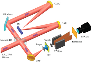
Figure 1. Schematic of the experimental setup. An anti-reflection coated plasma mirror ('PM') was employed to enhance the laser contrast. Two identical off-axis parabolic mirrors 'OAP1' and 'OAP2' were used to focus and re-collimate the laser pulses, respectively. The beam was then reflected by the 'HR mirror' and finally focused onto targets by the main 'OAP'. The 'Movable HR' is a high-reflection mirror mounted on a long-travel-range motorised translation stage providing a switch between low contrast and high contrast laser irradiations. The proton spatial intensity distributions and energy spectrum were measured by a stack of RCF films and a Thomson parabola spectrometer (TP-Spec) coupled with a scintillator detector and an EMCCD camera, respectively.
Download figure:
Standard image High-resolution imageThe S-targets used in this experiment were 5 μm-thick nickel targets with transverse dimensions of 500 μm. Stainless steel (Type 304, containing 69.3% Fe, 17.7% Cr,  Ni and other minerals) foils of 5 μm thickness with up to 20 mm transverse size were used as F-targets. Considering that the iron, chromium and nickel have close atom numbers and similar properties, and that protons are accelerated from the surface contaminant layer, the material difference on proton acceleration between the S-target and F-target is thus negligible.
Spatial intensity distributions of the accelerated proton beam were measured using a passive stack of radiochromatic films (RCF, type HD-V2) wrapped with a 14 μm-thick aluminum foil. The RCF films were positioned 40 mm behind the target along the normal axis. The optical density on each scanned layer is converted to dose distribution with the calibrated response curve. The proton beam radius is extracted by a circular fit to the footprint profile on each RCF layer, which gives the beam divergence by taking into account of the RCF-to-target distance. The proton energy corresponding to each RCF layer is modeled with the Monte Carlo ion transport code, SRIM [17].
A Thomson parabola spectrometer (TP-Spec) was used to measure the proton energy spectra along the target normal axis 200 mm behind the rear surface. The sampling solid angle is 5 × 10⁻⁶ sr with an entrance pinhole of 250 μm in diameter. A plastic scintillator (type EJ-264) coupled with an imaging EMCCD system was used to provide online data acquisition. A 2 μm-thick mylar coated with 200 nm-thick aluminum was placed before the scintillator to block scattered-light and stop heavier ions. The energy response curve of the scintillator has been calibrated by Green et al [18], which is used in extracting the proton spectra. The influence of the mylar filter is also accounted for during the data analysis.
3. Results and discussions
The effects of the target transverse size and laser contrast on beam divergence as a function of proton energy are shown in figure 2(a). Consistent with previous reports, the divergence angles for all cases decrease with proton energy [19]. In LC situation, the proton divergence angles from S-targets are about  larger than that from F-targets for all the sampled energies. Two notable changes are observed when the laser contrast is high. Firstly, beam divergences are reduced at all energies, by a factor of 1.3–1.6, for F-target. In comparison, the reduction is only observed at about 1 MeV for S-target. Meanwhile, the divergences are almost identical in the high energy region for the two contrast cases. Secondly, the maximum proton energy increases for S-target, while no significant changes are measured for F-target, which are consistent with the spectrum measurement shown later on.

Figure 2. (a) The energy-dependent divergence angles of protons from S-targets and F-targets. The blue dots and purple squares refer to results from S-target by low contrast (LC) and high contrast (HC) laser pulses, respectively. The red triangles and black diamonds are from F-targets for the two laser contrast cases. The errorbars are due to shot-to-shot variations and uncertainties in beam radius fitting. Below are example RCF images presenting the spatial intensity distributions of 1.1 MeV protons from (b) F-target with LC laser, (c) F-target with HC laser, (d) S-target with LC laser and (e) S-target with HC laser irradiations.
Download figure:
Standard image High-resolution imageExample spatial intensity distributions of proton beams with an energy of 1.1 MeV measured with RCF are presented in figures 2(b)–(e). The target used in figure 2(d) is a triangle with a side length of 500 μm, and in figure 2(e) is from a disk target with 500 μm diameter. Ring structures can be observed in figures 2(b) and (d) in LC situation. For S-targets, three zonal stripe structures in figure 2(d) and thin radial lines in figure 2(e) are observed. These patterns are perpendicular to the corresponding S-target boundaries, and thus identified as protons emitted from the S-target edges [20]. To notice that the divergence in figure 2(c) is significantly smaller than the rest of the three conditions, and complex structures (like the ring or stripe structures) are not observed.
Figure 3 shows the proton energy spectra measured by TP-Spec from S-targets and F-targets with laser parameters the same as in figure 2(a). Similar broad near-plateau structures from 2 to 6 MeV on the spectral distributions are observed under LC condition for both types of targets. As the laser contrast is improved, the spectral shape for F-target changes to exponential with a fitted temperature of 0.97 MeV. The flux of protons below 5 MeV increases by one order of magnitude as well. By comparison, the plateau structure remains and gets even broader, from 2.5 to 9.6 MeV, for S-target. Despite a lower laser intensity ( , due to the finite reflectivity of plasma mirror surface), the maximum proton energy is increased by
  in the HC case (also seen in figure 2).

Figure 3. Proton energy spectra measured with TP-Spec along the target normal direction. The blue and purple lines are proton spectra from S-targets irradiated by the LC and HC laser pulses, respectively. The red and black lines are from F-targets for the respective contrast cases. All the spectra have been background subtracted. The green line is the background sampled alongside the spectrum from F-target in LC condition (in red line).
Download figure:
Standard image High-resolution imageProton spectra similar to the near-plateau structure in figure 3 have been reported previously [21, 22]. A two-temperature model was proposed to describe the shape of the spectra [22]. Although the low energy part may be fitted with a certain temperature, it is difficult for the high energy regions to make a similar fitting as they are not in exponential distribution, especially for the S-target under HC. The flat spectrum could be most probably due to a combination of collisionless shock acceleration (CSA) and TNSA [23, 24]. We would like to emphasize that our main concern in this work is the spectral shape changes, instead of spectral shape itself. A more detailed discussion on spectral shape has been reported elsewhere [24].
Since the TP-Spec only samples a small fraction of total proton beam, we integrate the doses in the whole beam on each RCF layer. The overall proton spectra are then extracted by considering the total doses together with the calculated proton stopping curve. The results are shown in figure 4. The shapes of the overall proton spectra appear similar for all four combinations of investigated targets and laser contrasts. The exponential spectral shapes suggest that the TNSA proton acceleration mechanisms are fundamentally dominant for both types of targets in LC and HC cases. In addition, the proton flux from the S-targets is higher than that from F-targets in either contrast case. This corresponds to an increase in laser-proton energy conversion efficiency. Similar enhancement was also reported before [15, 25], although much smaller targets were used in their experiments.

Figure 4. Overall proton energy spectra. The spectra are extracted by integrating the dose distribution on each RCF layer, together with the calculated stopping curve using SRIM [17].
Download figure:
Standard image High-resolution imageCombining the results from figures 2–4, it comes up with a suggestion that there is a correlation between the spectral shape and the beam divergence. When the divergence angle is large, a near-plateau structure appears on the energy spectrum. In contrast, when the proton beam becomes collimated, the spectral shape changes into exponential. By comparing the sampled and the integrated proton spectra, and taking into account the differences in beam divergence, we consider the near-plateau structure along the target normal direction as a direct result of enlarged beam divergence. For LC laser irradiation, the low energy protons emit into large angles, while the high energy part remains relatively collimated. When sampling the proton beam with a fixed small angle, a reduction on flux of lower energy protons is expected, which gives rise to the near plateau spectrum.
The intense ASE pedestal (1012 W cm−2, 2 ns) is believed to be responsible for the large beam divergence in the LC case. Firstly, preplasma induced by intense ASE could expand to a scalelength of tens of micrometers which defines the major fast electron generation mechanisms and propagation patterns into the target [26]. Proton beam profile will be affected by the different injection schemes of fast electron beam in various preplasma conditions [27] and by the modified envelope shape of sheath fields [28, 29]. Secondly, the target rear surface expansion and deformation can be raised by an ASE-driven shock wave, which may also lead to a large proton divergence [30, 31]. The ring structure on the RCF in figures 2(b) and (d) infers that target deformation could happen in our experiment. In the HC case, steeped density profile at the front surface and unperturbed flat rear surface are expected. Even though the total proton flux is a bit lower (see figure 4), the collimated beam in the target normal direction could still be produced with higher flux from F-targets.
In order to evaluate the deformation of the target rear surface, we apply a simple analytic model, which was presented by Lundh et al [32] using a quasi-two-dimensional scheme. When a laser pulse with an intensity IASE irradiates on the target with the initial density of  , front surface plasma expansion exerts a pressure
  on the target and thus a shock could be launched. Here P is in units of Pa and IASE in W m−2. The material specific term
  is for a laser wavelength of 800 nm. The shock wave travels at a speed
  , where c0 is the sound velocity, vp is the particle velocity and α is an empirical material constant. The pressure and the shock wave velocity are correlated through momentum conservation as
  . When the shock wave propagates to the rear surface, the surface starts to expand with the speed of
  , where
  . For iron target, c0 = 3.77 μm ns−1,
  g cm−3 and
  [33], these give rise to a shock speed
  μm ns−1 and an expansion speed
  μm ns−1. It is sufficient for the shock to traverse a 5 μm-thick target and induce a target deformation after the 2 ns-duration ASE. While for HC laser, the shock speed
  μm ns−1 and the target rear surface will stay undisturbed before the main laser peak arrives.
A 2D hydrodynamic code MULTI2D [34] was further employed to model the plasma conditions of 5 μm-thick targets of different sizes irradiated with ASE pedestal at a series of intensities. Plasma density map and temperature distribution at 2 ns after irradiation are shown in figures 5. Significant deformation of the rear surface can be observed with ASE intensity at 1012 W cm−2 (shown in figures 5(a) and (c)), as well as remarkable plasma heating and expansion (shown in figures 5(e) and (g)), which could well explain the large divergence angles measured in LC condition. As for the HC condition, the rear surface of S-target and F-target (figures 5(b) and (d)) are not disturbed by the ASE of 1010 W cm−2. The simulation results indicate that in our experiment the preplasma distributions were not modified for the S-targets in comparison to the F-targets. It is worthwhile to note that the HC-laser-induced preplasma is incapable of propagating around the front surface and reaching the rear side for a target of 500 μm in transverse size (as seen in figure 5(d)). Therefore, the preplasma formed on the front side will not affect the sheath field evolution built near the rear surface.
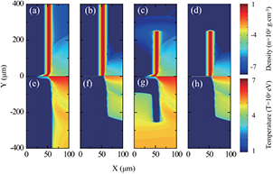
Figure 5. 2D plasma density map (a)–(d) and temperature distribution (e)–(h) in logarithm scales at t = 2 ns after the ASE pedestal arrives, simulated with 2D hydrodynamic code MULTI2D. The laser is incident from the right-hand side along the y = 0 axis. The laser pedestal intensity is 1012 W cm−2 in (a), (c), (e) and (g) and 1010 W cm−2 in (b), (d), (f) and (h), which corresponds to LC and HC lasers in experiment, respectively. The targets are  m in thickness. Absorption boundaries are applied in (a), (b), (e) and (f) to simulate infinite F-targets, while (c), (d), (g) and (h) are from S-targets of 500 μm in diameter.
Download figure:
Standard image High-resolution imageA major and new observation in this work is that the proton emissions from S-targets have no significant difference in spectra shape and beam divergence going from low contrast to high contrast in comparison to those of the F-targets. The fact that no ring structure is observed on RCF in figure 2(e) and the hydrodynamic simulation results in figures 5(b) and (d) help to rule out the possibility of shock-wave induced target deformation and plasma expansion at the S-target rear surface in HC condition. The simulation also produces similar preplasma distributions to the F-targets in the front side, which suggests the fast electron generation and injection in the two types of targets have no fundamental difference. Therefore, the preplasma effect could also be eliminated.
The effect of small target transverse size could be the best candidate for the abnormal behavior of S-targets under different laser contrasts. The three zonal stripe structures in figure 2(d) and the thin radial lines in figure 2(e) indicate that notable fast electron lateral transport and reflection from boundaries exist in both LC and HC situations. Fast electrons beam refluxing enhances the acceleration sheath field or extends the acceleration time [14]. This effect is also measured from the increased maximum proton energy from S-targets in comparison to the F-targets. Proton source sizes extending up to hundreds of microns have also been reported from laser systems with similar pulse duration [22]. It is therefore believed that the target boundary is also capable of modifying the accelerating sheath field shape and consequently affecting the accelerated proton beam profile.
To justify the hypothesis of sheath field modification in transverse-size-reduced targets, 2D PIC simulations with the KLAP-2D code [35] were performed. P-polarized (along the y axis) laser pulse is normally incident onto plasma. The overall size of the simulation box is  , where
  is the laser wavelength in vacuum. The transverse dimension of the target is from
  . A
. A  vacuum gap is left to simulate the target edge. Absorbing boundaries are employed. The laser pulse ramps up with a sine-squared profile within
  , where
  is the laser period, and then decreases sine-squared to zero in
  . The peak intensity is set to be
  W cm−2 and focal spot is
  in diameter (FWHM) with a Gaussian profile. The laser is incident from the left side into the simulation box along the
  -axis. The initial density of the main target is 5 nc, and a
  layer of hydrogen is set at the rear surface as the proton source. Here
  cm−3 is the critical density for 800 nm laser wavelength.
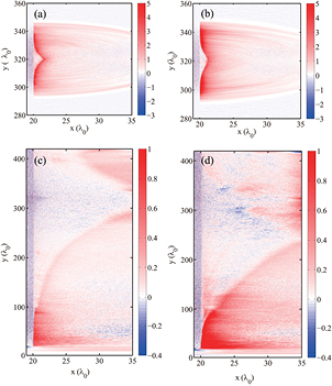
Two different preplasma distributions are applied, and contour levels of the components of the electric field Ex at the rear side of the target are shown in figure 6 at  and
and  . For figures 6(a) and (c) a preplasma of
  scalelength,
  thickness (simulating the HC laser case) and a maximum density of 5 nc is placed before the main target. The field distributions are symmetric at the early time. The propagation of electric fields (Ex) along the target surface (i.e. along y-axis) is observed. The fields at the later time have complicated distributions, i.e. enhanced at the edges and asymmetrically distributed. The enhanced sheath field at the target edge gives rise to the zonal or radial patterned proton emissions as pointed out in figures 2(d) and (e). For figures 6(b) and (d), an
  -thick preplasma with
  scalelength is applied to simulate the LC case. Similar field propagation patterns and distribution symmetry broken down are observed, suggesting electron lateral spreading and refluxing at the rear surface. The proton accelerating sheath field modification and the enhancement at the target edges are not exclusively determined by the laser contrast.
Figure 6. The 2D PIC simulation results on spatial distributions of electric field Ex at two time steps  ((a), (b)) and
  ((c), (d)), where (a) and (c) are for the case with a small scale of preplasma (HC condition) and (b) and (d) for the case with a large scale of preplasma (LC condition). The laser is incident from the left edge into the simulation box along
  -axis. The strengths of the Ex are in normalized units, which is 0.51 TV m−1.
Download figure:
Standard image High-resolution image
In both contrast cases the sheath shapes are dramatically different from those generated from targets with infinite transverse size. Similar modifications due to electron lateral transportation and refluxing may explain the similar beam divergence and spectra shape in LC and HC situations for S-targets. The field at the target edge at  is stronger than that in the HC situation leading to more pronounced edge proton emission as observed in the experiment, which is consistent with previous results that larger scalelength preplasma could enhance the fast electron lateral spreading along the target surface [36, 37]. Due to limited computation capability, we could not run simulations for a longer time and with a larger simulation box to trace the proton beam distributions. However, the modified shape and distribution of sheath field could infer that the target transverse size plays a definitive role in proton generation even it is far larger than the laser pulse length. This will extend our understanding of proton beam optimization when using a transverse-size-reduced target.
4. Conclusion
In summary, we have demonstrated that there are remarkably different effects of laser contrast on proton emissions from transverse-size-reduced targets and normal large foils. We find a correlation between beam divergence and spectral shape. In the case when the laser contrast is low, a near-plateau shape proton spectrum appears and the beam divergence is large for both types of targets. In the case when the plasma mirror is used and the laser contrast is high, proton beam properties are significantly changed only for the normal large target, i.e. its divergence is reduced considerably and the energy spectrum is changed to an exponential distribution. A similar large divergence and the near-plateau spectral shape remain for transverse-size-reduced targets. The results are explained by the preplasma formation, target deformation and modified accelerating sheath field evolution in transverse-size-reduced target, and supported by the 2D hydrodynamic and PIC simulations. The results will have invaluable implications in actively shaping the proton spectra or collimating the beam for applications.
Acknowledgments
We acknowledge financial support from the National Basic Research Program of China (Grant Nos. 2013CBA01502), the National Natural Science Foundation of China (Grant Nos 11421064 and 11205100), and National Key Scientific Instrument Development Project (Grant Nos.2012YQ030142).