


Abstract
TCV is presently undergoing major heating upgrades, installing a neutral beam for direct ion heating and increasing the electron cyclotron (EC) power injected in X-mode at the third harmonic (X3). The neutral beam is under construction at BINP-Plasma LLC (Russia), with energies of 18–35 keV and power up to 1 MW for 2 s. The injection of 1 MW 30 keV D-beam will allow access to regimes with Ti/Te > 1 and βN ∼ 2.8 in L- and H-mode, with densities compatible with X3 EC heating. A lower energy and power (20 keV, 0.5 MW) D NBI is suitable for lower densities with X2 EC heating and current drive. The vacuum vessel has been modified to allow for the beam tangential injection, necessary for beam access and to minimize shine through and orbit losses. The X3 upgrade consists of adding two dual-frequency gyrotrons (X2/X3, 126 GHz/84 GHz) with a total power of 2 MW. In addition, to explore solutions to the exhaust problem in tokamaks and test innovative solutions like the snowflake divertor in the presence of a closed divertor chamber, we are considering inserting new in-vessel modular structures, generating a divertor aperture with variable closure.
Export citation and abstract BibTeX RIS
1. Introduction
The TCV tokamak is characterized by the most extreme plasma shaping capability worldwide, the highest microwave electron cyclotron (EC) power concentration in the plasma, and a large degree of flexibility in its heating and control schemes. Its main missions are to contribute to the physics basis for a more efficient ITER exploitation, and for the optimization of the tokamak concept, plasma scenarios, and heating and control techniques in view of DEMO [1]. This requires access to plasma regimes and configurations with high normalized plasma pressure, a wide range of temperature ratios, including Te/Ti ∼ 1, a significant population of fast ions and relatively low collisionality [2]. These conditions will be reached by an upgraded TCV heating system: installing a neutral beam (NB) for direct ion heating and increasing the EC power injected in X-mode at the third harmonic (X3). Further substantial improvements in the TCV infrastructure are under examination. Additional power in the dual-frequency gyrotron systems is envisioned, to complete and maintain the heating capabilities in regimes of relevance for burning plasma conditions. To explore solutions to the crucial problem of the heat and particle exhaust, yet maintaining a good degree of flexibility, we are considering inserting new in-vessel modular structures, generating a divertor aperture with variable closure. Innovative solutions like the snowflake divertor need in fact to be proven viable in the presence of a closed divertor chamber, which allows for high neutral density in the divertor, and of an effective pumping system for particle control.
2. Plasma scenarios in the upgraded TCV
High confinement modes are typically obtained in highly elongated and relatively high density, high current plasmas [3]. On TCV, these plasmas cannot be heated using the 82.7 GHz EC system, which corresponds to the second electron cyclotron harmonic (X2), as the 82.7 GHz waves cannot propagate in plasmas with density above 4 × 10¹⁹ m−3, except in O-mode, where the absorption is low and the operational window small. Additional heating at higher density, as required for H-modes, may be achieved by upgrading the existing third harmonic (X3) EC system, whose frequency, 118/126 GHz, corresponds to a cut-off density of 1.2 × 10²⁰ m−3.
The simulation of the plasma scenarios was performed using the ASTRA code [4], which solves equations for electron and ion temperatures and plasma current density. The electron density profile and total plasma current are provided as inputs on the basis of actual TCV discharges. Neoclassical ion heat conductivity is used [5], with an ion temperature profile that is matched to the CXRS measurements [6]. The value of the electron heat conductivity is rescaled to obtain the energy confinement time predicted by the IPB98(y,2) scaling for ELMy H-modes, and by standard power law regression for L-modes [7]. The EC power deposition profile is calculated by the TORAY ray-tracing code.
As shown in figure 1, which is obtained from an ASTRA simulation of a standard TCV configuration, to approach the ITER relevant range of normalized β values (βN ∼ 2−2.5), X3 power levels higher than the presently available 1.5 MW are necessary. However, figure 2 shows that, even with the injection of additional X3 EC power, TCV plasmas would have Te/Ti in the range 2–5, outside the ITER, DEMO and reactor relevant domain. This is due to the naturally weak electron–ion coupling in small devices such as TCV, where the electron–ion collision times are substantially longer than the energy confinement time.

Figure 1. ASTRA simulation of the TCV plasma performance as a function of X3 power (left), and NB power (right), based on an actual scenario (H-mode discharge 29892, with Ip = 410 kA, BT = 1.44 T, Zeff = 2.6, ne(0) = 6.5×10¹⁹ m−3, Te(0) = 2.8 keV, Ti(0) = 0.9 keV, q95 = 2.5; the shaping parameters are κ95 = 1.68 and δ95 = 0.36). Here and in the following figures an NBI D-beam of 30 keV is considered, together with the ITER H98 confinement scaling, with χi = χe/2.
Download figure:
Standard image High-resolution image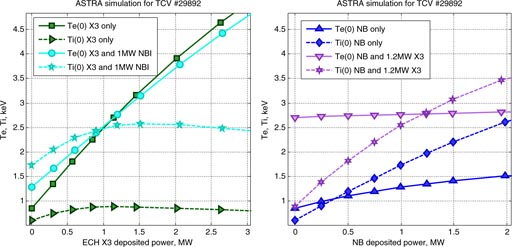
Figure 2. Variation of the electron and ion on-axis temperatures as a function of EC X3 power (left) and NB power (right) from ASTRA simulations, for the same cases shown in figure 1.
Download figure:
Standard image High-resolution imageAs illustrated by figure 2, to have Te/Ti ∼ 1, the ion population must be heated directly using neutral beam injection (NBI). In such conditions, the turbulence is dominated by other modes than those observed so far (mixed ITG-TEM). The resulting different characteristics for heat, particle and momentum transport give rise to important open questions for the core of burning plasmas. Combined with the upgraded X3 ECH system, a new NBI system on TCV could bring the plasma to the β-limit in H-mode (βN ∼ 2.8) [8], an important point for ITER and DEMO [9], provide variation to the momentum input to the plasma, and generate fast ions for studying wave–particle interaction phenomena of interest for burning plasmas. Figure 2 shows that in TCV plasmas of similar shape to ITER, the condition Te/Ti ∼ 1 is met for about 1 MW of NB power absorbed in discharges with about 1 MW of X3 ECH. With a combination of an NB up to 1 MW and up to 1.3 MW of X3 ECH, Te/Ti is foreseen to vary between 0.5 and 3.0 in the TCV high (H-mode) [10] and improved density (IN-mode) [11] confinement regimes.
3. Neutral beam heating on TCV
These simulations show that the injection of 1 MW 30 keV deuterium beam will allow access to regimes with Ti/Te > 1 and βN ∼ 2.8 in H-mode, at high density (>4 × 10¹⁹ m−3), compatible with X3 EC heating. A lower energy and power (18–20 keV, 0.3–0.5 MW) deuterium NB is on the other hand suitable for experiments at intermediate densities ((1–3) × 1019 m−3) and lower plasma current (120–250 kA) with second harmonic X2 EC heating and current drive. Further constraints for the TCV NB system design stemmed from the issues of beam access, shine through and orbit losses, which all favoured a tangential injection [8].
Substantial modifications to the TCV vacuum vessel were required for installing two ports, providing the possibility of adding a second beam in the future, each with an aperture of 170 × 220 mm2, through which 1 MW of power can be injected (see figure 3). Such modifications were performed in situ, with a substantial fraction of the machining and welding done from inside the vacuum vessel. Prior to the intervention, finite element analysis of the relevant mechanical stresses proved that the addition of the two new openings would have no significant impact on the structural properties of the vacuum vessel. The internal configuration of the graphite first wall has been changed to fit with the two new apertures, and tiles with special geometry and high heat load capability have been added to protect the beam facing elements in the area of beam–wall interaction. The beam dump uses graphite tiles that are tolerant to a full duration (1 s) full power beam injected into a vertically centred plasma with on-axis electron density higher then 2.0 × 10¹⁹ m−3. According to finite elements simulations, the surface temperature would only reach ∼1200 K.
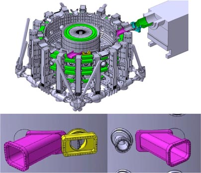
Figure 3. Top: schematic view of the TCV vessel with the two new tangential ports and NB injector. Bottom: detail of the modification of the vessel to remove the existing radial ports and the introduction of the tangential ports.
Download figure:
Standard image High-resolution imageThe NB is being built by Budker INP (Russia) [12]. It will cover an energy range of 18–35 keV, with tunable power up to 1 MW, and 2 s duration. The injector design incorporates a standard positive ion source with an average nominal current density of 3 kA m−2. The plasma emitter is formed in a plasma box with up to 40 kW of inductively coupled RF power at ∼4 MHz, with 15 kV at the multi turn RF coil. To focus the beam inside the TCV port at ∼3.6 m from the ion source, the grids are formed in spherical segments [13]. The radius of the plasma electrode is 4 m, and 3 m for accelerator and ground grids. The geometry of the grid elementary cell was optimized to minimize the beam's angular divergence and power losses in the beam duct especially in the TCV port. A slit geometry of the elementary grid cell was chosen. Slits are placed inside the 250 mm diameter area. The beam emitter has intrinsically anisotropic angular divergence along and across slits (8 × 18 mrad for the individual slits, and overall 12 × 20 mrad) [14]. The main elements of the TCV NB system, plasma grid geometry and NB power density distribution at the entrance in the tokamak are shown in figure 4.

Figure 4. Main elements of the TCV NBI: 1—RF plasma source, 2—magnetic screen, 3—ion-optical system, 4—neutral beam; 5—alignment unit; 6—ions source gate valve; 7—vacuum tank; 8—cryopump cold head; 9—liquid nitrogen volume; 10—cryo-panels, 11—neutralizer, 12—bending magnet, 13—diaphragm, 14—ion dump for positive ions, 15—calorimeter, 16—aiming device, 17—temperature field of the plasma grid exposed by 2 s beam, deposited power 12 kW, maximal temperature 137 °C; 18—NB power density (maximum 92.5 MW m−2) on the exit from the port in the TCV, 1 MW transmitted.
Download figure:
Standard image High-resolution imageThe basic characteristics of the NB system for TCV are summarized in table 1. The upper limit for the beam energy of 35 keV is compatible with the orbit losses in plasma with currents up to IP = 400 kA. The tunability in power 0.3–1.0 MW within the same discharge is required to investigate the plasma response to various levels of ion heating in otherwise identical discharge conditions. The first NB operations on TCV are scheduled for mid-2015.
Table 1. Main characteristics of the NB system for TCV.
| NB injector reference scenario | |
|---|---|
| NB power injected in TCV | 1 MW |
| Nominal beam energy | 30 keV |
| Max. NB pulse duration | 2 s |
| Beam full energy fraction in power | ⩾65% |
| NB operation domain | |
| Beam power range | 30–100% |
| Beam energy range | 15–35 keV |
| Beam main species | DO and HO |
| Power sweep during TCV shot | 30–100% |
| Power sweep response (P/(dP/dt)) | ⩽0.3 ms |
| Full power modulation on-time | 10 ms–2 s |
| Minimal modulation off-time | 5 ms |
| Modulation rise/fall time | ⩽0.5 ms |
| Fast modulation at reduced power | 100–300 Hz |
4. X3 gyrotron power upgrade
The X3 upgrade project consists of adding two dual-frequency gyrotrons (126 GHz/84 GHz) with a total power at 126 GHz (for top-launch X3) or at 84 GHz (for low field side (LFS) injection X2) of 2 MW [12]. The three existing gyrotrons operating at 118 GHz will be relocated to inject power from the LFS using the existing X2 transmission lines and launchers (figure 5): single pass absorption in excess of 70% can be achieved even in this configuration in plasmas pre-heated by top-launch X3. Bulk electron heating will then be ensured by the 2 MW from the top launcher, while localized deposition necessary for MHD control will be possible with the 1.5 MW launched from LFS. The same transmission lines and power supplies presently used for top-injection of the 118 GHz gyrotrons will be used. Similarly, the same high voltage power supply will be used for either X2 or X3 LFS launch as required by the experimental program. The design of the new dual-frequency gyrotron (126 GHz/84 GHz) will be carried out at CRPP with contributions from the Karlsruhe Institute of Technology (KIT), and will be based on the gyrotron (140 GHz/1 MW/CW) manufactured by Thales Electron Devices for the W7-X stellarator. The X3-upgrade is planned to be fully operational by the end of 2018.

Figure 5. Layout of the upgrades EC X2–X3 system on TCV.
Download figure:
Standard image High-resolution image5. Towards a more closed divertor structure on TCV
In addition to the heating upgrades, an even more substantial modification is under consideration: the insertion of a new modular structure at the edge of the plasma to explore innovative solutions to the crucial problem of the heat and particle exhaust, one of the main physics and technology challenges for ITER and, even more dramatically, DEMO. ITER will need to accommodate a power to the device walls of the order of 100 MW, resulting in peak heat fluxes of 10 MW m−2 in the conventional divertor configurations, at the limit of the capabilities of present materials. The DEMO device will need to have a size similar to ITER, for clear economics reasons in view of a possible commercial deployment of fusion reactors, but higher exhaust power, therefore this limit will be exceeded by a large factor. In addition the plasma fluence onto material surfaces in a power plant will be several orders of magnitude higher than in today's experiments, leading to intolerable material erosion. Peak heat fluxes and material erosion constitute clear potential showstoppers for fusion. Alternative advanced edge and divertor solutions must be found. These innovative concepts need to resolve the challenge of power handling, avoiding material erosion of the surfaces exposed to the plasma whilst preserving adequate core plasma fusion performance.
The proof of principle of one possible solution, the snowflake divertor, was obtained for the first time on TCV. However, to be considered for DEMO, solutions like the snowflake divertor need to be proven viable both from the point of view of plasma scenarios and from that of the engineering design compatibility with reactor constraints. This implies a comprehensive study of the plasma behaviour at the edge, and of the interface between edge and core. The plasma in the divertor chamber should be detached from the wall, radiate most of its power, rather than deposit it in the form of particle fluxes, and give rise to a hot boundary layer surrounding a pure plasma core. A device with flexible shape and configurations, like TCV, provides the most effective way to make progress in this direction, as long as some conditions, necessary for a fusion reactor, are met. These conditions are a closed divertor chamber, which allows for high neutral density in the divertor, and an effective pumping system for particle control.
To achieve these conditions and maintain the flexibility necessary for a comprehensive scientific investigation and to optimize possible candidate configurations represents a challenge that no magnetic fusion device in the world can tackle at present. We propose to modify the TCV in-vessel structures to make this possible on TCV (see figure 6). In particular, we aim at developing a flexible divertor aperture with variable closure and combined with an effective pumping system. Solutions such as the insertion of a fixed aperture on the outer wall of the machine and a movable aperture on the inner wall to accommodate various magnetic divertor configurations will be explored. Particle control will be achieved by adding high capacity pumps such as cryogenic pumps in the divertor chamber. In order to remain true to the TCV philosophy, the pumping system must be effective for a wide range of magnetic configurations and target locations. The possibility we intend to explore is to clad the entire divertor chamber with pumped divertor targets, which could consist of poloidal carbon-armoured fingers that cover the pump ducts, a solution that was successfully deployed in the toroidal pump limiter of the TORE SUPRA tokamak [15]. In addition to guaranteeing particle control in highly radiating scenarios, such a pumping system would also extend the operational range of other TCV scenarios to control plasma densities thereby opening new opportunities for the scientific exploitation of the TCV facility, such as ECRH-X2 heating, current drive or stability control in H-modes. We note in addition that the most recent divertor design for MAST upgrade also includes a very closed divertor chamber [16]. Optimal trade-offs between installing these new structures in the existing vacuum vessel and building a new vessel, or new portions of it, will also be considered.

Figure 6. Left: photo of the TCV vessel in its present configuration. Right: example of internal structure creating a closed–pumped divertor chamber in TCV, in the presence of a snowflake divertor. The elements protruding from the vessel at the left and at the right are the inner and outer divertor apertures, respectively, while the red elements are the pumped divertor targets.
Download figure:
Standard image High-resolution image
6. Conclusion and outlook
The on-going heating upgrades (1 MW NBI and 2 MW of additional X3 EC) will enable TCV to access β values in the same range of ITER or higher, and a wide range of Te/Ti values, including Te/Ti ∼ 1. This will open the way to investigations of innovative plasma exhaust configurations, ELM control, transport and shape studies, and to disentangle effects of electron–ion coupling, rotation, current density profile, edge density control and shape, in ITER and reactor relevant ELMy H-mode with dominant electron heating. Various plasma configurations will be tested, from JET and ITER like conventional shapes to plasmas with high elongation (so far produced in TCV only in ohmic discharges), snowflake divertors, and divertor plasmas with negative triangularity, which have lower β limits but better confinement than with positive triangularity.
The upgraded TCV tokamak is one of the three national tokamak facilities in Europe that are retained as essential for the implementation of the European Fusion Roadmap, which aims at providing fusion power on the grid by 2050. Further substantial improvements in the TCV infrastructure are currently under examination, to make it an even more central element in the Roadmap, and a hub for innovation towards novel fusion reactor concepts. Additional power in the dual-frequency (X2/X3) gyrotron systems is envisioned, to complete and maintain the heating capabilities in view of regimes of increased relevance for burning plasma conditions. Substantial diagnostic improvements would also be undertaken, in the areas of waves in the THz range of frequencies, and of advanced imaging systems in the visible, infrared, and mm-wave ranges. In addition, the pre-design phase has been started for a major in-vessel modification, to produce a closed divertor chamber, allowing for higher neutral density in the divertor and an effective pumping system for particle control. Naturally, the advantages of such modification will need to be evaluated in the framework of a dedicated modelling effort, which we plan to undertake in the near future.
Acknowledgments
This work was supported in part by the Swiss National Science Foundation. This work has been carried out within the framework of the EUROfusion Consortium and has received funding from the European Union's Horizon 2020 research and innovation programme under grant agreement number 633053. The views and opinions expressed herein do not necessarily reflect those of the European Commission.