
Abstract
The combination of a dedicated acceleration stage with direct extraction of ions from a low-pressure wire discharge enables one to generate a narrow band ion beam of tunable energy. In order to optimize this ion source concept, we conduct a numerical study emphasizing the main physical processes and the parameters controlling them. An analysis of the three-dimensional non-collisional ion trajectories inside the ion source reveals that the total beam current can be tuned by modifying the depth and radius of the diaphragm connecting the wire discharge chamber to the acceleration chamber, while the inter-electrode distance controls the beam focusing. A particle-in-cell (PIC) modelling of the beam acceleration and propagation indicates that, despite the low operating pressure (∼10−2 mbar), elastic and charge-exchange collisions are responsible for a decrease in the beam current by a factor of four. Charge-exchange collisions are also shown to be accountable for the existence of a low-energy ion population being non-uniform throughout a beam cross section.
Export citation and abstract BibTeX RIS
1. Introduction
A wire-induced plasma source (WIPS) [1], or a wire discharge, is a type of low-pressure gas discharge relying on a purely electrostatic confinement of electrons. This efficient confinement scheme permits low-pressure (∼10−5 mbar) gaseous discharges at very low applied voltages (∼1 kV) within a chamber a few centimetres in size.
Drawing on WIPS-based secondary emission electron guns' operating principles [2], an ion source concept relying on the extraction and acceleration of ions from a low-pressure WIPS was proposed [3]. Experimental measurements have shown that such an ion source can produce ion beams of various ionic species up to a few tens of micro-amperes, and having a limited energy spread (∼10 eV) around an easily tunable energy [3]. This narrow band energy feature has been demonstrated to be a direct consequence of the properties of the diffuse mode of the discharge [4] of the WIPS. The addition of a dedicated acceleration stage has indeed been shown to result mainly in a shift by the acceleration voltage of the distribution function of the ion beam velocity component along the extraction axis of the ion source, the width of the distribution function remaining close to that of the ion beam directly extracted from the WIPS. Such beam properties make this ion source an interesting candidate for various applications, among which are space micro-propulsion [5], ion beam diagnostics and sensor calibration. A discussion of these beam properties in terms of space propulsion capabilities can be found in [6].
The addition of a dedicated acceleration stage in fact permits one, in complement with Fitch's original direct extraction ion source concept [7–9], to tune the beam energy almost independently of the beam current. In the meantime, experimental results show that the acceleration stage combined with the extraction diaphragm acts as an electrostatic lens [3]. The beam spatial extension is therefore controlled by the accelerating voltage and the WIPS discharge voltage. Nevertheless, the inter-electrode distance being much longer than the diaphragm radius, the system cannot be described as a classical two-cylinder electrostatic lens [10], and the beam spatial properties depend on a larger number of parameters.
A better understanding of the dependence of the beam properties as a function of the various geometric parameters of the ion source would allow one to minimize the beam divergence, to maximize the total beam current or to control the beam current density at a given distance of the ion source. These improvements, leading to a higher reduced brightness [11], would significantly enhance the application potential of this ion source. However, the parametric analysis of the beam properties being intrinsically hardly measurable by experiments as each parameter modification would require an opening of the vacuum tank on which the ion source is mounted, such an investigation has to be conducted numerically.
In this paper, we first analyse the dependence of the beam properties as a function of various pre-identified parameters using a three-dimensional non-collisional ion optic code coupled to a particle-in-cell (PIC) modelling of the sole WIPS in section 2. Then, we quantify the influence of the collisional phenomenon inside the acceleration stage by means of a PIC modelling of this region in section 3. Finally, results are synthesized in section 4.
2. Parametric analysis
The analysis of the dependence of beam properties as a function of the various geometric parameters of the ion source prototype requires the use of a numerical tool sufficiently fast to permit an analysis over various parameters and operating conditions, but, in the meantime, sufficiently refined to capture the physics of the problem. In this section, we first identify the geometric parameters of interest, we then present the modelling approach adopted for the parametric study and demonstrate its capabilities, and finally the numerical results are discussed.
2.1. Parameters studied
A cut view of the complete ion source simulation domain and of the extraction and acceleration regions of interest is sketched in figure 1. Ions are extracted through a cylindrical diaphragm of radius Rd and of depth zd drilled into the WIPS cathode. Ions extracted through the diaphragm are then accelerated towards a grounded electrode taking the form of a disc being drilled in its centre. The accelerating electrode hole has the same radius Rd, and a thickness h. The distance between the WIPS cathode and the accelerating electrode is denoted as d.

Figure 1. Ion source concept sketch. Wire discharge voltage Vd, accelerating voltage Vf and wire anode potential Vs = Vf + Vd. The parameters whose influence is characterized are d, Rd and zd.
Download figure:
Standard imageDue to the large value of the ratio d/Rd, the focal length of the electrostatic lens system formed by the extraction diaphragm and the accelerating electrode is not strictly a function of Vs/Vd, in contrast to the case of an ideal two cylinder electrostatic lens [10]. The inter-electrode distance d and the diaphragm radius Rd are therefore two natural candidates for the parametric study. In addition, the modification of the electric field inside the WIPS chamber becoming more important as the diaphragm depth is increased, the diaphragm depth zd is also a parameter of interest for characterization of the beam.
The three parameters studied are consequently the diaphragm radius Rd, the inter-electrode distance d and the diaphragm depth zd. The values of these parameters used in the experimental study of the ion source [3] were chosen identical to those which have been shown experimentally to optimize the performance of secondary emission electron guns, and are given in table 1.
Table 1. Default values of the three parameters studied.
| Parameter | Value (mm) |
|---|---|
| Diaphragm radius Rd | 4 |
| Inter-electrode distance d | 16 |
| Diaphragm depth zd | 6 |
2.2. Numerical approach
The adopted numerical model consists of the simulation of the three-dimensional non-collisional trajectories of ions. These ions are generated with thermal energy inside the WIPS according to the normalized ionization rate per unit volume—ionization rate per unit volume divided by its maximum value over the whole volume—obtained by PIC simulation of the sole WIPS [4] for a given set of operating conditions (pressure and discharge current). Ions' trajectories are then integrated in the electric field computed from the electric potential field calculated as the sum of the space charge electric potential field inside the WIPS—obtained by PIC simulations—plus the Laplacian potential distribution resulting from the electrode configuration. Charge effects are therefore neglected anywhere but inside the wire discharge.
The simulation domain is limited in the direction of the beam propagation at 6 cm of the accelerating electrode, which corresponds to the position of the retarding potential analyser (RPA) used during the experimental characterization of the beam [3].
As illustrated in figure 2, a large number of ions (typically 10 000) are generated inside the wire chamber, and the trajectory of these ions is computed until they impact the inner surfaces of the ion source. Currents are monitored on various surfaces of interest: the wire discharge cathode, the diaphragm boundaries, the accelerating electrode and a surface corresponding to the area of the RPA diaphragm used while conducting experimental measurements [3] (1.25 mm in radius). The total ion beam current passing through the accelerating electrode is computed as well.
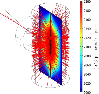
Figure 2. Three-dimensional trajectories of ions generated inside the WIPS chamber. Accelerating voltage Vf = 2000 V. Discharge voltage Vd = 200 V.
Download figure:
Standard imageDue to the limited fraction of ions passing through the extraction diaphragm as opposed to ions impacting the wire discharge cathode, the number of ions forming the ion beam is limited. In fact, the diaphragm cross section represents about 3% of the surface of the wire discharge cathode. The number of simulated ion trajectories passing through the diaphragm is therefore very low. The generation of ions inside the whole wire discharge cavity as opposed to the generation of ions in the sole longitudinal wire discharge slice in which ions might escape the discharge through the diaphragm is, however, a necessary requirement to get access to a quantitative estimate of the total ion beam current. As a matter of fact, the total ion beam current can only be estimated by comparing the number of ions extracted through the diaphragm with the number of ions impacting the WIPS cathode for a given discharge current. As a consequence, due to the low fraction of ions extracted, the simulation is reproduced between 10 and 20 times for each operating condition to maximize the signal-to-noise ratio.
The evolution of the on-axis current density with accelerating voltage Vf obtained by the numerical simulation is plotted along experimental data measured using a RPA in figure 3. The RPA data were cross-correlated by Faraday cup measurements in order to demonstrate its ability to estimate the beam current density once grid transparency is taken into account. Before any further comment, one can see that the numerical results exhibit non-negligible uncertainty levels, despite the fact that the results are averaged over a few tens of iterations. Nevertheless, the results clearly demonstrate that the consideration of space charge density inside the WIPS chamber is necessary to reproduce the peak of current density for a given accelerating voltage as observed experimentally. Once the space charge potential inside the WIPS is taken into account, the predicted evolution of the on-axis current density with accelerating voltage matches fairly well with the experimental one. However, the current density levels obtained by the numerical simulation are about four times larger than those obtained by experimental measurements. This behaviour can be explained by remembering that collisional effects are neglected in this numerical approach. In fact, despite the low operating pressure of the wire discharge (p = 2.2 × 10⁻² mbar in helium), the large elastic and charge-exchange cross sections for helium ions with background neutrals—about 2 × 10⁻¹⁹ m2 for an helium ion having a kinetic energy of a few hundreds of electron volts [12]—yield approximately three collisions for an ion on its way to the WIPS cathode. The longer path of ions extracted through the diaphragm leads to an even higher number of collisions. Therefore, ions suffering elastic collisions being scattered isotropically, collisions diffuse the ions' trajectory. As a result, the measured ion beam current downstream of the accelerating electrode decreases, and the ion current to the electrodes (WIPS cathode, accelerating electrode) increases. Consequently, the collisional processes of ions with a background neutral gas can be reasonably invoked to justify the factor four observed between experimental and non-collisional numerical data in figure 3. The influence of these collisional processes will be quantitatively analysed in section 3

Figure 3. On-axis current density evolution with accelerating voltage of an helium ion beam at 6 cm of the accelerating electrode. WIPS discharge voltage Vd = 200 V, WIPS discharge current Is = 2 mA, pressure p = 2.2 × 10⁻² mbar.
Download figure:
Standard imageOnce normalized, numerical data match fairly well with the experimental one, which demonstrates the validity of this numerical approach to conduct a parametric study over the geometric parameters previously identified.
2.3. Dependence of the beam properties on the ion source geometric parameters
The on-axis current density evolution as a function of the accelerating voltage is plotted for various values of the geometric parameters zd, Rd and d in figure 4.

Figure 4. On-axis current density evolution with accelerating voltage of an helium ion beam at 6 cm of the accelerating electrode. WIPS discharge voltage Vd = 200 V, WIPS discharge current Is = 2 mA, pressure p = 2.2 × 10⁻² mbar. Dependence over (a) the inter-electrode distance d, (b) the diaphragm depth and (c) the diaphragm radius.
Download figure:
Standard imageLooking at the role played by the inter-electrode distance d (figure 4(a)), a modification of d leads mainly to a shift in the accelerating voltage
 giving rise to the on-axis current density maximum, together with a small variation of the maximum current density level. This trend can be physically interpreted as a consequence of the decrease in the influence of the accelerating electrode on the electric potential distribution inside the diaphragm as this very electrode is further moved away from the wire plasma source. The accelerating voltage required to focus the ion beam at a given distance of the accelerating electrode thus increases with d.
As shown in figure 4(b), a strong dependence of the on-axis current density properties on the diaphragm depth zd is observed. This behaviour can be analysed as follows. First, an increase in the diaphragm depth being possibly seen as a limitation of the ion acceptance angle, a large diminution of the on-axis current density maximum is observed when the diaphragm depth zd increases. Second, as the divergence of the beam entering the diaphragm is reduced when zd is increased, the accelerating voltage required to focus the ion beam at a given distance of the accelerating voltage decreases. Dependence of the evolution of the on-axis current density with the accelerating voltage Vf on the diaphragm radius Rd, as highlighted in figure 4(c), can be explained in similar terms: a decrease in the diaphragm radius leads, at the same time, to smaller current density levels and lower values for the accelerating voltage
maximizing the on-axis current density.
Although the relatively high computation cost of the method makes it hard to explore the parameter space extensively, the data plotted in figure 4(c) show that the dependence of the evolution of the on-axis current density j with the accelerating voltage Vf on the diaphragm radius Rd is determined well by

in the diaphragm radius and accelerating voltage ranges considered. The dependence of the current density on the ratio of the diaphragm radii
 and
and
 results from the scaling of the beam current with the extraction area. The fact that the accelerating voltage Vf for which a given current density is obtained scales with the diaphragm radius Rd can be interpreted by considering that a change in the diaphragm radius yields a modification of the potential distribution inside the diaphragm, and thus a modification of the beam focusing [3].
The observation that the diaphragm connecting the wire discharge chamber to the acceleration chamber limits the angle of acceptance of ions and thus the ion beam current is confirmed by the data plotted in figure 5. In fact, a limitation of the diaphragm depth and an increase in the diaphragm radius both yield a lower ion current collected on the diaphragm wall (figure 5(a)), which leads to a higher ion beam current (figure 5(b)). In addition, the weak dependence of these ion currents on the inter-electrode distance designates the diaphragm dimensions as the geometric parameters of primary importance with respect to the optimization of the ion beam current.

Figure 5. Influence of the ion source geometric parameters on the generated ion beam: (a) ion current collected on the diaphragm walls and (b) ion beam current.
Download figure:
Standard imageTo summarize, the parametric study points out the diaphragm radius Rd as well as the diaphragm depth zd as control parameters with respect to the ion beam current, while the inter-electrode distance d is shown to control the beam focusing. A combined modification of these parameters should indeed allow one to maximize the ion beam current while maintaining a given divergence of the beam.
3. Influence of collisional processes
The numerical approach implemented within the framework of the parametric study conducted above enabled the qualitative rendering of the on-axis current density data obtained experimentally. However, a discrepancy between measured and experimental current levels was observed. It was postulated that collisional processes, which were not taken into account in the numerical study, are responsible for this difference. In this section, we seek to quantify the influence of these collisional effects on the ion beam properties using a PIC modelling of the ion source extraction and acceleration regions. We first introduce the simulation scheme used to simulate the ion source behaviour with a two-dimensional code, and then identify the role played by the collisional processes on both the current levels and the ion energy distribution function of the beam.
3.1. Model assumptions
The PIC modelling of the complete ion source being intrinsically time consuming due to the combination of small features—the wire anode—with large spatial extension and many time steps, a full three-dimensional analysis remains hardly achievable. In order to overcome this issue, we choose to decouple the problem, using the results of the PIC study of the sole wire discharge [4] as input data for the 2D/3V electrostatic PIC modelling of the extraction and acceleration regions of the ion source. Experimental results indicating a weak modification of the wire discharge behaviour by the extraction of ions give credit to the adopted numerical scheme.
The simulation domain is given in figure 6. The geometric dimensions are the same as the ones used for the experimental set-up as well as for the parametric study. The electric boundary conditions are prescribed as follows: a null normal field is specified on the ion source axis (r = 0), the particle inlet (z = 0) and the radial outer boundary; while electric potential φ is imposed on the WIPS cathode (φ = φf) and the accelerating electrode (φ = 0) as well as the axial outer boundary (φ = 0) mimicking the RPA housing. A relative permittivity εr = 3.3 is specified in the region covering the Plexiglas dielectric shielding, and the Poisson equation is solved over the whole domain. Secondary emission of electrons by ion impact is modelled on the various physical surfaces using energy-dependent secondary emission coefficients for copper (accelerating electrode) [13] and aluminium (WIPS cathode) [14] targets bombarded by helium ions.

Figure 6. Simulation domain.
Download figure:
Standard imageGas being introduced at one end of the system and pumped at the other, a number density gradient exist inside the computational domain. Due to the relatively low operating pressure of the wire discharge (p ⩽ 10−2 mbar), the number density field inside the domain is computed using a DSMC simulation [15, 16]. However, the ionization fraction in the discharge being negligible (∼10−4), this simulation is carried out a priori, and the number density field obtained is used as an input data of the PIC simulation.
The simulation runs until the current balance over the domain boundaries converges to zero. The velocity distribution function of the ions at the diaphragm entrance is the one obtained from a PIC simulation of a WIPS discharge operated at a discharge current of 10 mA and a pressure p = 2.2 × 10⁻² mbar in helium. The ion current through the inlet is 32 µA, which is the current value obtained assuming a complete decorrelation between the WIPS operation and ion extraction.
3.2. Current density levels
The ion beam current density map obtained numerically at 6 cm of the accelerating electrode is compared with the experimental data in figure 7. The total ion beam currents computed by integration of these current density maps are, respectively, 8.5 µA and 9.7 µA for numerical and experimental data once the RPA transmission factor (0.56 per grid) is taken into account. Beyond this good agreement observed in terms of the total ion beam current, the maximum current density level obtained by simulation matches fairly well with the one obtained by experiments. The decrease observed on the radial profile is very similar on both maps, the main difference being the inability of the code to reproduce the azimuthal asymmetry. This feature is, however, a direct limitation of the two-dimensional axisymmetric modelling which de facto presupposes an invariance of the ion beam properties by rotation of angle θ. In addition, the fact that a similar current density level and total ion beam currents are observed for a lower pressure in the experimental data might be explained by the location of the pressure gauge. Indeed, in order not to perturb the wire discharge, the pressure gauge is not directly connected to it, but localized slightly upstream of the wire cavity.

Figure 7. Current density maps at 6 cm of the accelerating electrode: (a) simulation and (b) experimental data.
Download figure:
Standard imageThe quantitative agreement obtained between experimental and simulated current density levels points, as suggested in the previous section, the collisional phenomenon as the main factor yielding a decrease in the ion current density. In addition to this contribution, through the PIC modelling giving access to the ion velocity distribution function throughout the whole computational domain, the influence of the collisional effects on the energy distribution function while the ion beam is formed and accelerated can be analysed.
3.3. Modification of the ion energy distribution function
The on-axis energy distribution function of the ion beam obtained by the PIC simulation is plotted in figure 8. There are three main regions of interest.

Figure 8. Energy distribution function along the ion source axis obtained by PIC simulation at 6 cm of the accelerating electrode. Accelerating voltage Vf = 2 kV.
Download figure:
Standard imageFirst, the simulation confirms the existence on a narrow energy spread—full-width at half-maximum of about ten eV—ion beam for an energy corresponding to the sum of the accelerating (Vf) and discharge (Vd) voltages.
Second, the simulated spectrum exhibits a peak for an energy equal to the accelerating voltage (Vf). This peak, unobserved in the experimental data, is a numerical artefact resulting from the choice of a Neumann boundary condition for the Poisson solver on the inlet. This choice, imposed by the simulated domain configuration, results in an underestimation of the electric field along the ion source axis at the diaphragm entrance. This behaviour, combined with charge-exchange phenomenon, leads to the formation of ions having a similar energy. A simulation on a larger domain permitting reproduction of the potential distribution accurately at the diaphragm entrance should indicate that those ions are indeed generated inside a region of larger potential axial gradient, spreading in turn the peak in a wider energy range.
Third, the numerical simulations underline the existence of a population of ions having an energy lower than the accelerating voltage. As can be seen in figure 9, the experimental data corroborate this result. Moreover, these experimental results indicate that the existence of this population is conditioned by the operation of the discharge at high pressures.
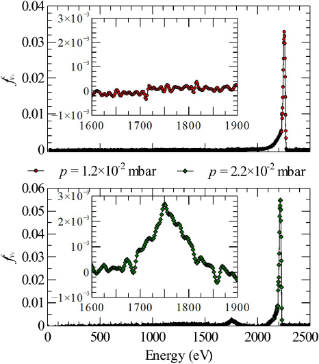
Figure 9. On-axis energy distribution function along the ion source axis obtained by experiments at 6 cm of the accelerating electrode for two operating pressures of the WIPS. Accelerating voltage Vf = 2 kV.
Download figure:
Standard imageA thorough analysis of this low-energy ion population indicates, as highlighted in figure 10, that the energy of the ions forming this population decreases with the radial position in the exit plane. In fact, whereas the two major peaks are still obtained, respectively, for Vf and Vf + Vd, the mean energy of the low-energy ion population decreases as the analyser is further moved away from the ion source axis. This behaviour can be interpreted by analysing the electric potential distribution inside the diaphragm together with the computed radial position in the exit plane of ions generated with null kinetic energy inside the diaphragm, which are representative of ions generated by charge-exchange collisions.
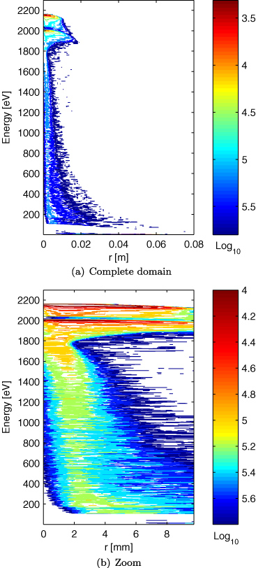
Figure 10. Iso-contours of the energy distribution function along the ion source axis at 6 cm from the accelerating electrode: (a) complete domain and (b) zoom on the region of interest.
Download figure:
Standard imageDue to the relatively low ion beam current obtained, the space charge effects inside the acceleration region remain negligible. Indeed, the potential drop δφ across the diaphragm induced by a supposedly uniform ion number density ni is

where e is the ion charge and Rd is the diaphragm radius. Considering a uniform singly ionized helium ion beam of a few tens of micro-amperes having a kinetic energy  i of about 200 eV—typical value of the discharge voltage Vd in the diffuse mode—the number density is

and the potential drop δφ is of the order of a volt. The potential drop resulting from the electrode geometry being at least ten times more important, the space charge effects are indeed negligible. Individual trajectories of ions generated inside the diaphragm can consequently be computed in a Laplacian formalism.
Figure 11(a) presents the radial coordinate of ion impact on the RPA (at 6 cm from the accelerating electrode) as a function of the initial position of the ion. Ions are generated inside the diaphragm and the acceleration region with zero velocity, and are therefore representative of ions produced by charge-exchange collisions in these regions. The evolution can be divided into two components. First, the ions generated inside the diaphragm (z < 6 cm) impact the RPA in a large range of radial positions. In the meantime, due to the specification of the Neumann boundary condition on the inlet, the electric potential distribution remains almost constant in this region (figure 11(b)). This trend justifies the existence of the non-physical peak of the ion energy distribution function for an energy Vf in a large range of radial positions. Second, the radial position of impact on the RPA of ions generated inside the acceleration region (z > 6 cm) increases with the initial axial position. In between, the potential drops almost linearly with the axial position z. Consequently, the mean kinetic energy of ions impacting the RPA decreases with the radial position of impact. This behaviour thus justifies the decrease in the energy of the low-energy population as the RPA is moved further from the ion source axis, as highlighted in figure 10.

Figure 11. Origins of the low-energy ion population. Accelerating voltage Vf = 2000 V.
Download figure:
Standard imageTo summarize, the collisional effects are shown (i) to yield a decrease in the ion beam current by a factor of four, (ii) to give rise to a low-energy population of ions generated inside the diaphragm and the acceleration region by charge-exchange collisions with the background neutral gas. Therefore, a development permitting the operation of the wire discharge at lower pressures in its high-pressure mode (diffuse mode) would enable the generation of higher beam currents without significantly increasing the power demand. Indeed, the major power demand consists in the operation of the wire discharge, while a much lower fraction of it is devoted to the acceleration of the extracted ion beam. Modifications of geometrical parameters, e.g. the WIPS anode and end plates hole radii, yielding a decrease in the applied voltage necessary to operate the discharge at a given voltage and current have already been proposed [1], but give rise in turn to other constraints, such as a limitation of the discharge current. Another way of operating the wire discharge at lower pressures in its high-pressure mode might lie in the addition of an axial magnetic field sufficiently strong to magnetize electrons, which would potentially enhance the electron confinement in the discharge, the gain offered by a lower intensity axial magnetic field having been shown [17] to be limited in the case of small anode radii. Finally, a practical solution would consist in a differential pumping of the acceleration region. If such a solution was to be implemented, one could think of operating the wire source at higher pressures [18] so as to benefit from the advantages in terms of beam properties—well-defined energy spread in particular—of ion extraction from a quasi-neutral plasma. The number densities would, however, have to be limited in such a way that the Debye length remains larger than the diaphragm diameter in order to avoid beam defocusing inside the diaphragm [19].
4. Summary
In this paper, a numerical study emphasizing possible optimization of an ion source derived from a low-pressure wire discharge is reported, with special attention given to the means of optimization of the produced ion beam properties.
A three-dimensional ion optic code is first used to determine the non-collisional trajectory of ions inside the ion source. This ion optic algorithm uses the results—ionization and space charge electric potential fields—of a 2D/3V PIC modelling of the sole wire discharge as input data, and process the ion trajectory in the combined (Laplacian and space charge inside the WIPS) electric field. A statistical analysis over the computed ion trajectories is used to determine the parameters of main importance among three pre-identified geometric parameters. The diaphragm connecting the wire discharge chamber to the acceleration chamber is pointed out as the key region when looking at the optimization of the ion beam current. In between, the inter-electrodes distance is shown to control the divergence of the beam, enabling in particular the focusing of the beam at a given distance of the accelerating electrode. In principle, a combined design of these two regions should therefore permit the generation of an ion beam of a given beam spot size and current at a given distance of the accelerating electrode.
A PIC modelling of the ion extraction and acceleration regions is then used to quantify the influence of collisional effects. It reveals that collisional effects are responsible for a decrease in the beam current. Despite the low operating pressure (about 10−2 mbar in helium), a factor of four is indeed reported between the on-axis current density obtained by non-collisional simulation and experimental data. In addition, the generation of ions of originally negligible kinetic energy by means of charge-exchange collisions inside the diaphragm and the acceleration region is shown to give rise to an ion population of energy lower than the accelerating voltage. Due to the combination of (i) the decrease of the electric potential along the ion source axis and (ii) the increasing radial deflection undergone by ions as ions are generated further from the accelerating electrode, the mean energy of the low-energy ion population decreased as the analyser is moved further away from the ion source axis.
The importance of collisional effects being lower as the WIPS operating pressure is decreased, a decrease in the limit pressure required to operate the WIPS in its diffuse mode (high pressure) would result in a significant increase in the beam current as well as a narrower energy spectrum of the beam. Various improvements of the actual source design which could permit meeting this objective have been identified: diminution of the anode radius, diminution of the WIPS end plates hole radius, magnetization of electrons, etc.