


ABSTRACT
Two-dimensional hybrid simulations are performed to investigate the interaction of Alfvén waves with a perpendicular shock self-consistently. The perpendicular shock is formed by reflecting the particles in the right boundary, and it propagates to the left. The Alfvén waves are injected from the left boundary, and they are convected toward the right. The results show that the injected Alfvén waves have no obvious effects on the propagation speed of the shock. However, after the upstream Alfvén waves are transmitted into the downstream, their amplitude is enhanced about 10–30 times. The transmitted waves can be separated into two parts, and both of them are left-hand polarized Alfvén waves: one propagates along the +y direction and the other along the −y direction. Obvious ripples in the shock front are also found due to the interaction of the Alfvén waves with the shock. The great enhancement of the amplitude of the Alfvén waves by the shock is verified by the satellite observations. The implications of the simulation results to the influences on the diffusive shock acceleration are also discussed in this paper.
Export citation and abstract BibTeX RIS
1. INTRODUCTION
Particle acceleration is a ubiquitous phenomenon at shock waves, and occurs on scales from supernova remnants to interplanetary shocks and cometary bow shocks. Diffusive shock acceleration is the mechanism considered to be responsible for the almost universally observed power-law spectra of energetic particles from cosmic rays to gradual solar energetic particle (SEP) events (Axford et al. 1977; Bell 1978; Blandford & Ostriker 1978). The theory of diffusive shock acceleration is successful in explaining SEP observations at quasi-parallel shocks (Zank et al. 2000; Li & Zank 2003). At a quasi-parallel shock, the upstream ions reflected by the shock stream far upstream along the magnetic field, and excite low-frequency plasma waves by plasma beam instabilities (Gary 1991; Lu et al. 2006). The waves make the ions to be scattered across the shock several times. In this way, these particles can be accelerated to very high energies, forming a power-law spectrum (Lee 1983; Zank et al. 2000, 2007; Li & Zank 2003; Giacaclone 2004). A similar theory does not work at quasi-perpendicular shocks. At a quasi-perpendicular shock, the reflected upstream ions return to the shock immediately due to the gyromotion of the particles in the magnetic field. So the excited waves by energetic particles are not generated in situ, thus limiting particle scattering (Wilkinson & Schwartz 1990; Gordon et al. 1999; Yang et al. 2009). These particles escape the shock rapidly. Therefore, it is difficult to accelerate particles to high energies and explain the observed power-law spectra of the energetic particles at quasi-perpendicular shock waves.
Recently, cross-field diffusion by large-amplitude intrinsic magnetic turbulence has been suggested to play an important role in particle acceleration at quasi-perpendicular shocks. Particles following irregular random walking magnetic fields are able to cross the shock repeatedly. In this way, particles can also be accelerated to high energies (Giacaclone 2005a, 2005b; Zank et al. 2006), and the observed power-law spectra of energetic particles at quasi-perpendicular shocks can be explained (Zank et al. 2006). Therefore, the interaction of upstream Alfvén waves (a proxy for solar wind turbulence) with a quasi-perpendicular shock plays an important role in particle acceleration at quasi-perpendicular shocks. The interaction of Alfvén waves with shocks has been investigated by many authors. With a small amplitude linear analysis, McKenzie & Westphal (1969) investigated the transmission of Alfvén waves through the Earth's bow shock, and found that the magnetic field of the transmitted Alfvén waves is about three times larger than that of the incident waves. McKenzie & Volk (1982) studied the interaction of the cosmic-ray-generated Alfvén waves with a parallel shock, and found that one of the modified slow magnetoacoustic waves is unstable. Webb et al. (1999) derived equations describing the interaction of weakly nonlinear short-wavelength magnetohydrodynamics (MHD) waves with cosmic-ray-modified shocks. In these studies, the profiles of the shocks were fixed, and they were not affected by the Alfvén waves. Zank et al. (2002) considered a self-consistent approach in which the Rankine–Hugniot jump conditions are modified by turbulence, allowing for an approximately self-consistent solution. Finally, Ao et al. (2008) investigated the structural response of a MHD shock to upstream turbulence, finding that the shock can become distorted, sometime smoothed, with non-Rankine–Hugnoiot jumps in strength. In this paper, we use two-dimensional (2D) hybrid simulations to investigate the interaction of Alfvén waves with a perpendicular shock self-consistently. The amplification and characteristics of the transmitted Alfvén waves, as well as the modification of the shock front by the injected Alfvén waves, are investigated.
The paper is organized as follows. In Section 2, we describe the hybrid simulation model, The results are presented in Section 3, and in Section 4 the conclusions are given. Here relevant observations are presented and the implications to particle acceleration at quasi-perpendicular shocks are discussed.
2. HYBRID SIMULATION MODEL
In a hybrid simulation, ions are treated kinetically and electrons as a massless, charge-neutralizing fluid (Winske 1985). It is a well-known self-consistent plasma simulation method that has been used extensively to study the space plasma. In this paper, the plasma consists of proton and electron components, and the two-dimensional hybrid simulations are performed in the x–y plane. Initially, protons satisfy a Maxwellian velocity distribution with a drift speed along the x-direction, and a uniform background magnetic field  (where
  is the unit vector along the y-direction) is assumed to be along the y-direction. Particles are injected from the left boundary with a speed of Vb = 4.0VA (where
  is the Alfvén speed based on the upstream magnetic field B0 and number density n0, and mp is the mass of the proton), and the plasma beta upstream of the shock is βp = 2μ0p0/B20 = 0.5 (where p0 is the upstream pressure). The number of grid cells is nx × ny = 600 × 256, and the grid sizes are Δx = 0.512c/ωpp and Δy = 1.0c/ωpp(where c/ωpp = VA/Ωp is the proton inertial length and
  is the proton plasma frequency based on the upstream number density n0). The time step is Ωpt = 0.02 (where Ωp = eB0/mp is the proton gyrofrequency based on the upstream magnetic field B0). To form the shock, we reflect the plasma at a rigid right boundary wall at x = xright. A shock propagating to the left is formed. Periodic boundary conditions for the particles and fields are used in the y-direction.
3. SIMULATION RESULTS
We describe here three case studies: (1) one with no injected upstream Alfvén waves, (2) a case with a single monochromatic Alfvén wave injected from the left boundary and its wavelength is 64c/ωpp, and (3) a simulation comprising a mixture of sinusoidal Alfvén waves injected from the left boundary, and their wavelengths are 85.33c/ωpp, 64c/ωpp, 51.2c/ωpp, and 42.67c/ωpp, respectively. The wavelengths for case (3) correspond to 1/3, 1/4, 1/5, and 1/6 of the domain size along the y-direction. The corresponding power spectrum of the waves has a Kolmogorov power-law index −1.667, which is a generally accepted value in the solar wind (Villante 1980; Bavassano & Smith 1986). In both cases (2) and (3), the injected Alfvén waves have the same wave amplitude ∑kδB2k/B20 = 0.25 in the left boundary, where k denotes the wave mode. Below, we describe the simulations for cases (2) and (3) first, and then compare them to case (1).
Figure 1 shows the distributions of the magnetic field components (a) Bx/B0, (b) By/B0, and (c) Bz/B0 at Ωpt = 40, 80, and 130 for case (2). The perpendicular shock propagates from the right boundary along the −x direction with a speed of about 1.5VA and an average compression ratio of about 3.6. Considering that the upstream plasma drift along the +x direction with a speed of Vb = 4.0VA, we can calculate that the shock Alfvén Mach number is 5.5. The downstream By is about 3–4 times that of the upstream, which is consistent with the MHD Rankine–Hugoniot relations. The monochromatic Alfvén wave injected at the left boundary is convected toward the shock. At about Ωpt = 56, the Alfvén wave begins to interact with the shock. Obvious ripples can be found at the shock, which distort the shock front. The transmitted Alfvén wave experiences large amplification of the fluctuating magnetic fields B2x and B2z. The enhanced waves are then convected to far downstream slowly.
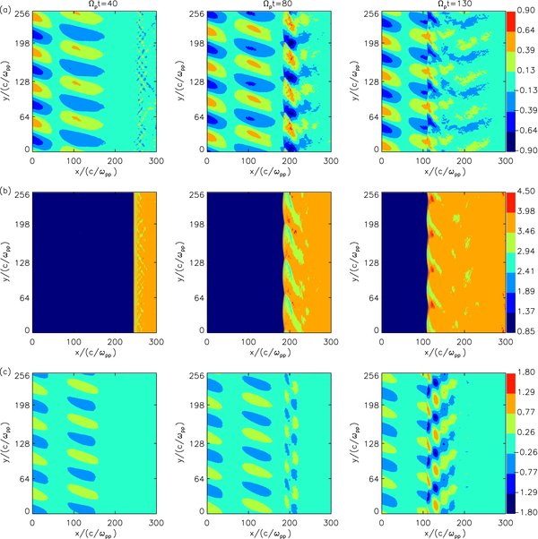
Figure 1. Distributions of the magnetic field components: (a) Bx/B0, (b) By/B0, and (c) Bz/B0 at Ωpt = 40, 80, and 130 for case (2).
Download figure:
Standard image High-resolution imageThe enhancement of the fluctuating magnetic field after transmission through the shock can be demonstrated more clearly in Figure 2, which shows the average of the fluctuating magnetic field (B2x + B2z)/B20 along the y-direction versus x at Ωpt = 80 for case (2). The fluctuating magnetic field increases rapidly from about 0.015 just upstream of the shock to about 0.26 downstream of the shock. Therefore, the amplitude of the fluctuating magnetic field can be enhanced as large as about 17 times. There is no enhancement of the transmitting waves at the downstream region where the fluctuating magnetic field has not reached. Figure 3 shows the distributions of the amplitude of the fluctuating magnetic field (B2x + B2z)/B20 at Ωpt = 80 for case (2). The enhancement of the fluctuating magnetic field B2x + B2z is different at different y positions, and at some positions the enhancement can be as large as 30 times.
Figure 2. Average of the fluctuating magnetic field (B2x + B2z)/B20 along the y-direction vs. x at Ωpt = 80 for case (2).
Download figure:
Standard image High-resolution image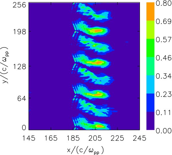
Figure 3. Distributions of the amplitude of the fluctuating magnetic field (B2x + B2z)/B20 at Ωpt = 80 for case (2).
Download figure:
Standard image High-resolution imageTo investigate the characteristics of the transmitted wave through the shock, we describe the polarizations of the wave at different positions. In Figure 4, the left panel shows the spatial profiles of the magnetic field Bx/B0 and Bz/B0 at Ωpt = 80 for case (2). Three different positions at xωpp/c = (a) 148.48, (b) 191.488, and (c) 204.8., which represent upstream, immediate downstream, and downstream, respectively, are chosen; the right panel shows the corresponding hodograph of Bx − Bz from A(yωpp/c = 80) to B(yωpp/c = 0). The Alfvén wave experiences obvious amplification after transmitting the shock. The upstream wave is left-hand circularly polarized, which propagates along the +y direction. When the wave transmits the shock, its polarization becomes elliptically polarized until nearly linearly polarized at xωpp/c = 204.8. After separating the fluctuating magnetic field into positive and negative helical parts (Terasawa et al. 1986, Lu & Wang 2005), we find that the downstream fluctuating waves comprise two parts, and both of them are left-hand circularly polarized Alfvén waves: one propagates along the +y direction and the other along the −y direction. The amplitude ratios of these two parts (B2x + B2z)+y/(B2x + B2z)−y are about 3.06 and 0.95 at xωpp/c = 191.488 and 204.8, respectively. Figure 5 displays the spatial profiles of Bx/B0 and Bz/B0 at Ωpt = 80 for case (2), while (a) and (b) correspond to the parts propagating along the +y and −y directions at xωpp/c = 204.8, respectively. Our simulation results are consistent with the linear theory of McKenzie & Westphal (1969); the upstream Alfvén wave is enhanced greatly after transmitting a shock due to the compression of the shock. Simultaneously, the transmitted waves through the shock are separated into two parts: one is the Alfvén wave propagating along the +y direction and the other along the −y direction.
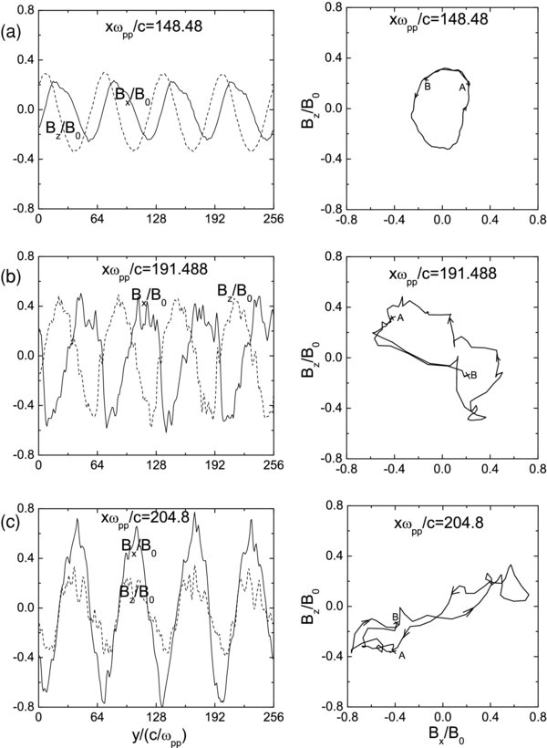
Figure 4. Left panel shows the spatial profiles of the magnetic field Bx/B0 (solid line) and Bz/B0(dash line) at Ωpt = 80 for case (2). Three different positions at xωpp/c = (a) 148.48, (b) 191.488, and (c) 204.8, which represent upstream, immediate downstream, and downstream, respectively, are chosen; the right panel shows the corresponding hodograph of Bx − Bz from A(yωpp/c = 80) to B(yωpp/c = 0).
Download figure:
Standard image High-resolution image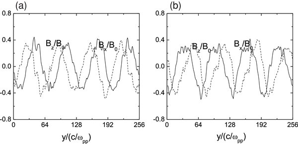
Figure 5. Spatial profiles of Bx/B0 (solid line) and Bz/B0 (dash line) at Ωpt = 80 for case (2), while (a) and (b) correspond to the parts propagating along the +y and −y directions at xωpp/c = 204.8, respectively.
Download figure:
Standard image High-resolution imageSimilar results are obtained for case (3), which comprises a mixture of sinusoidal Alfvén waves with wavelengths 85.33c/ωpp, 64.0c/ωpp, 51.2c/ωpp, and 42.67c/ωpp. Figure 6 shows the distributions of the magnetic field components (a) Bx/B0, (b) By/B0, and (c) Bz/B0 at Ωpt = 80 for case (3). Obvious ripples can be found at the shock front due to its interaction with Alfvén waves, and the ripples are not as regular as case (2). Again, we find that the amplitude of the fluctuating magnetic field ∑kδB2k is enhanced by a factor ranging from 10 to 50 after transmitting the shock.
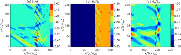
Figure 6. Distributions of the magnetic field components (a) Bx/B0, (b) By/B0, and (c) Bz/B0 at Ωpt = 80 for case (3).
Download figure:
Standard image High-resolution imageFigure 7 describes the average of the fluctuating magnetic field ∑kδB2k/B20 = ∑k(B2x + B2z)/B20 along the y-direction versus x at Ωpt = 80 for case (3). The fluctuating magnetic field is enhanced from 0.07 just upstream of the shock to 0.63 just downstream of the shock, which is about nine times. The amplitude of the fluctuating magnetic field changes greatly. Figure 8 shows the distributions of the amplitude of the fluctuating magnetic field ∑kδB2k/B20 at Ωpt = 80 for case (3). The enhancement of the fluctuating magnetic field B2x + B2z is also different at different y positions, and the enhancement can be as large as 50 times at some positions.
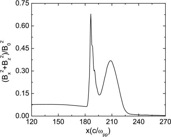
Figure 7. Average of the fluctuating magnetic field ∑kδB2k/B20 = ∑k(B2x + B2z)/B20 along the y-direction vs. x at Ωpt = 80 for case (3).
Download figure:
Standard image High-resolution image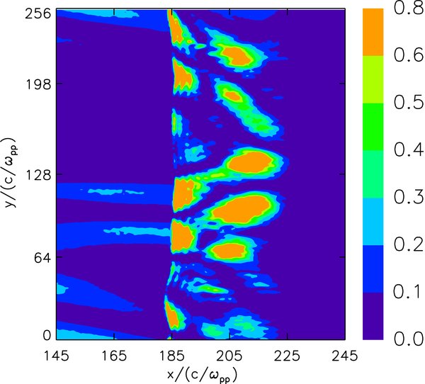
Figure 8. Distributions of the amplitude of the fluctuating magnetic field ∑kδB2k/B20 = ∑k(B2x + B2z)/B20 at Ωpt = 80 for case (3).
Download figure:
Standard image High-resolution imageIn order to identify more clearly the effects of the Alfvén waves on the shock, we compare the structures of the shocks in different cases. Figure 9 describes the distributions of the magnetic field component By/B0 (left panel) and the number density n/n0 (right panel) at Ωpt = 80 for three different cases: (a) is for case (1), while (b) and (c) are for cases (2) and (3). The shocks in these three cases are almost at the same location x = 185c/ωpp, and it means that the injected Alfvén waves have no obvious influences on the propagating speed of the shocks. For the cases with the existence of the injected Alfvén waves, ripples at the shock front (both the magnetic field and number density) can clearly be identified. The ripples are consistent with the Alfvén waves in the upstream, and they propagate along the y-direction with the Alfvén waves in the upstream. Therefore, the ripples have a regular structure for the case with the monochromatic Alfvén wave, while the ripples for the case with a mixture of Alfvén waves are irregular.
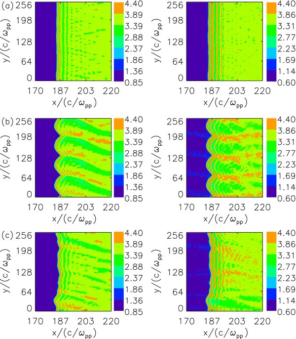
Figure 9. Distributions of the magnetic field component By/B0 (left panel) and number density (right panel) n/n0 at Ωpt = 80 for (a) case (1), (b) case (2), and (c) case (3).
Download figure:
Standard image High-resolution imageWe also change the plasma beta and other parameters, and find that the enhancement of the upstream Alfvén waves is insensitive to these parameters. Although the enhancement of the fluctuating magnetic field in our hybrid simulations seems to be consistent with the predictions in McKenzie & Westphal (1969), we also find that the enhancement is different at different y positions. In addition, the polarization of the transmitted waves is changing when they are convected to far downstream.
4. CONCLUSIONS AND DISCUSSION
In this paper, we used two-dimensional hybrid simulations to investigate the interaction of upstream Alfvén waves with a perpendicular shock. Upstream Alfvén waves have no obvious influence on the propagation speed of the shock, but structural modifications are clearly identified at the shock front. Furthermore, the amplitude of the Alfvén waves ∑kB2k is enhanced by a factor of some 10–30 after transmission. The transmitted waves can be separated into two parts, and both of them are left-hand circularly polarized Alfvén waves: one propagates along the +y direction and the other along the −y direction.
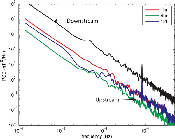
The enhancement of the amplitude of the Alfvén waves after transmitting the shocks can be verified by satellite observations of interplanetary shocks from the Advanced Composition Explorer (ACE). Figure 10 shows the magnetic field power spectral density (PSD) upstream (red, green, and blue lines) and downstream (black line) of such a shock, adapted from Zank et al. (2006), where the upstream PSDs were calculated for three intervals of increasing distances away from the shock. The PSD downstream was calculated for an interval immediately after the shock. The shock normal forms an angle of 92° ± 4° with an ambient upstream magnetic field. In upstream, no apparent enhancement of magnetic field fluctuations, often indicative of wave activities, is observed when the satellite approaches the shock. In downstream, the power of downstream fluctuations is enhanced by about an order of magnitude, consistent with our simulation results presented above.
Figure 10. Magnetic field PSD upstream (red, green, and blue lines) and downstream (black line) of a shock, where the upstream PSDs were calculated for three intervals of increasing distances away from the shock. The PSD downstream was calculated for an interval immediately after the shock. The shock normal forms an angle of 92° ± 4° with an ambient upstream magnetic field.
Download figure:
Standard image High-resolution image
Clear ripples can be identified at the front of the perpendicular shock after the interaction of upstream Alfvén waves with a shock. It means that the angle between the shock normal and the upstream magnetic field θBn changes at the shock front. Therefore, the shock front has an irregular shape, and is a mixture of planar shocks with different shock angles θBn. In this way, the dynamics of the reflected ions by the shock will be different from the case without injected Alfvén waves. How it will affect the mechanisms of ion acceleration at perpendicular shocks is our future topic.
We thank Garry Webb at the University of Alabama in Huntsville for valuable discussions. Q.M.L. was partly supported by the National Science Foundation of China (NSFC) under grants Nos 40725013, 40674093, 40874075, and Chinese Academy of Sciences (KJCX2-YW-N28).