


ABSTRACT
We study the dynamics of nano dust grains in the region inward from 1 AU. Assuming that the grains are created with the velocities close to Keplerian, we find that, despite the strong coupling to magnetic field, there is a population of trapped nano grains within about 0.2 AU from the Sun. The nano dust grains produced outside of the trapped region are accelerated to high velocities, of the order of 300 km s−1, provided that the charge to mass ratio is not much less than 10−5 e/mp. These values correspond to dust sizes equal or smaller than approximately 10 nm.
Export citation and abstract BibTeX RIS
1. INTRODUCTION
Several observational findings point to the existence of nano particles in the interstellar medium and in other astronomical objects, but there are only few observations of nano dust within the solar system. In these cases, the nano dust is detected by in situ measurements. During the space missions to comet Halley, dust measurements on the Vega and Giotto spacecraft suggested the presence of dust particles of 1–10 nm size in the vicinity of the comet (Utterback & Kissel 1990). The Ulysses dust experiment detected nano particles ejected from the Jovian magnetosphere (see Grün et al. 1993; Krüger et al. 2006b, and references therein); these nano particles were also detected by the Cassini plasma wave experiment (Meyer-Vernet et al. 2009b). The dust experiment on Cassini measured bursts of high velocity dust particles coming from Saturn's vicinity (Kempf et al. 2005). All these cases of nano dust detection in the solar system refer to nano dust from spatially limited sources and with velocities that are beyond Keplerian orbit velocities typical for dust in the interplanetary dust cloud.
Two recent observations suggest that there are significant fluxes of nano particles near Earth's orbit. Using the analysis of craters in the exposure foils that were located on the International Space Station for about two years, Carpenter et al. (2007) postulated the detection of dust with sizes smaller than 10 nm. The other observation is reported from the wave instrument (Bougeret et al. 2008) on the STEREO A spacecraft. Since its launch in 2007, this instrument has detected frequent intense voltage pulses which, in analogy with the similar events observed during other missions, can be interpreted as results of dust impacts. Assuming that the events observed by STEREO are caused by dust impacts leads to the estimated dust flux that exceeds by at least 2 orders of magnitude the flux expected for micrometer-sized dust (Kaiser et al. 2007). Moreover, the frequency of the STEREO A events is highly variable, which is not expected to be the case for micrometer-sized dust near 1 AU. Meyer-Vernet et al. (2009a) proposed that the events are caused by the impacts of nano dust and showed that nano dust impacting the spacecraft with very high velocity can generate the observed signals. The STEREO A results would be the first detection of nano dust in the interplanetary medium dust cloud.
The vast majority of dust in the interplanetary dust cloud of the solar system forms by collisional fragmentation of larger meteoroids. There is little information about the size limits of the fragments formed. Considerations of thermo-chemical properties suggest that nano particles can form and exist in the solar system inside 1 AU (Mann & Murad 2005). Calculations of dust trajectories show that dust with a charge to mass ratio of the order of 10−4 e/mproton can be accelerated to velocities of the order of the solar wind velocity (Mann et al. 2007).
In the following, we study the dynamics of nano dust particles by calculating the trajectories of particles with Q/m = 10−4–10−5 e/mproton in the solar magnetic field described by the Parker model with tilted current sheet. We treat the dust as test particles with fixed charge (the charge fluctuations are neglected). The approach is similar to calculations of pick-up ion trajectories by Luhmann (2003), but with much lower Q/m. We establish the size range for the grains that can be accelerated to large velocities. A model based on guiding center approximation is used to study the trapping of nano dust near the Sun. Assuming the formation of nano dust by collisions in the interplanetary dust cloud inside 1 AU, we estimate the characteristics (velocity averages and dispersions) of the velocity distribution of nano dust near Earth's orbit. Results of the calculations allow us to discuss the plausibility of the STEREO A results in view of our current understanding of the interplanetary dust evolution.
This paper is organized as follows. The model used in the simulations is described in Section 2. Section 3 discusses the energy conservation and the restriction on the size of accelerated nano dust. In Section 4, some features of nano dust trajectories (in particular, approximate independence on Q/m) are pointed out. Section 5 discusses trapping of the nano dust: a special model, based on the guiding center approximation, is presented there. The simulations using ensembles of nano dust grains are described in Section 6 together with the results for the average velocities and dispersions at 1 AU. In Section 7, the results of dynamical calculations are compared to observations and other theoretical work; also, we discuss briefly the nano dust beyond 1 AU, charging of the nano dust, and the destruction probability due to sublimation and sputtering. A summary is given in Section 8.
2. DESCRIPTION OF THE MODEL
The model used here is based on two important simplifications. First, we do not include short time scale variations of the magnetic field or of the solar wind parameters. Second, the charge to mass ratio Q/m is taken to be constant in time since the dust stays in a similar plasma environment and charge fluctuations because of photon impact occur on comparatively long time scales (see the discussion in Section 7.6).
The full equation of motion reads
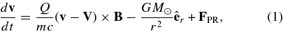
where v, Q, and m are the velocity, the charge, and the mass of the dust grain, V is the plasma velocity, B the magnetic field, and G the gravity constant. FPR is the Poynting–Robertson force term
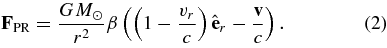
Here, β is the radiation pressure to gravity ratio for the dust grain and vr the radial component of the grain velocity. The value of β for the nano dust grains is expected to be small (β∼ 0.1) and the Poynting–Robertson force is a subdominant term in our calculations. In particular, taking only the term GM☉β/r2 instead of full FPR does not affect the results.
We assume that the solar wind velocity V is radially directed:  , with V dependent only on heliolatitude: V = 400 km s−1 in the slow solar wind region (|latitude
 ) and V = 800 km s−1 in the fast wind region (|latitude
 ). In most calculations,
  is also equal to the tilt of the heliospheric current sheet (for the case of zero tilt
  is set to 20°). We take the magnetic field to be described by the Parker spiral, with the unit vector
  tangent to the magnetic field line:
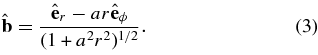
Here, a = (Ω/V)sin θ with Ω the angular speed of solar rotation and θ the colatitude. The magnetic field can be written as  , where
  is the radial component of B at r =
  = 1 AU. The sign and value of
  can vary between different magnetic field lines.
In our calculations, the value of  is taken to be different in the slow and fast solar wind regions. Specifically, we take
  where
where  , that is,
  35 μG in the slow and ≈45 μG in the fast solar wind. The sign is determined from the sign of
  , where
  is the solar dipole direction at the time t' = t − r/V. We use a simple picture of the solar surface divided by the tilted neutral line (taken to be a great circle) into two hemispheres, one with outgoing and the other with incoming magnetic field direction.
  is perpendicular to the plane of the neutral line.
Our assumption of radial, constant V plasma flow restricts the model applicability to r larger than the outer limit of the "intermediate zone" ∼10–20 R☉ (Schatten et al. 1969). For discussion of charged grain dynamics in the vicinity of the Sun, see Krivov et al. (1998) but only the grains larger than 0.1 μm are considered there.
3. ENERGY CONSERVATION AND ACCELERATION OF DUST GRAINS
The electric field −(1/c)V × B in our model can be written as
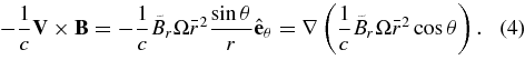
The latter equality holds in the region where  . In our model, this corresponds to any unipolar region with uniform solar wind speed. In such a region, the energy conservation equation becomes
or, with the index 1 used for final and 0 the initial state:
A change in kinetic energy is therefore related to the change in cos θ. This leads to a restriction on possible acceleration of the dust grains. For Q/m = 10−4, 10−5, and 10−6 e/mp, respectively,  equals about (1.5 × 108 cm s−1)2, (4.5 × 107 cm s−1)2, and (1.5 × 107 cm s−1)2. Since |cos θ0 − cos θ1| ⩽ 2, acceleration to the velocities of the order of 300 km s−1 is possible for Q/m = 10−4–10−5 e/mp but not for much larger (smaller Q/m) grains (for Q/m = 10−6 e/mp released at 0.2 AU, it would require the maximum value of |cos θ0 − cos θ1| = 2). This agrees with the results of our simulations (Figure 1).

Figure 1. Speed as a function of distance from the Sun for grains with Q/m = 10−7 e/mp to 10−4 e/mp released from a circular orbit of radius 0.2 AU close to the solar equator plane for the "focusing" magnetic field. The lines are numbered in the order of decreasing Q/m: (1) 10−4, (2) 10−5, (3) 7 × 10⁻⁶, (4) 5 × 10⁻⁶, (5) 3 × 10⁻⁶, and (6) 10−6, (7) 10−7. The "kinks" mark the crossings of the current sheet. The dashed lines correspond to opposite magnetic field orientation: note that no current sheet crossing is seen for this case.
Download figure:
Standard image High-resolution imageCrossing a current sheet is accompanied by a sign change in  , so that if on one side of the sheet the energy increase requires an increase in cos θ (northward drift), it would require a decrease in cos θ on the other side. For particles that encounter the current sheet, the correlation between the energy and latitude implied by Equations (5) and (6) is consequently obscured.
4. TRAJECTORIES OF THE NANO GRAINS
In this and the following sections, we present our results based on solving the equations of motion for the nano dust for different grain sizes, initial conditions, and configurations of the magnetic field. We find that the dust grains can either escape to large distances by being "picked up" by the solar wind or, if created close to the Sun (within about 0.15 AU if near the ecliptic), trapped in non-Keplerian orbits.
One effect of interest is the Q/m-independence of the grain trajectories. It occurs for the grains in the Q/m = 10−4 e/mp − Q/m = 10−5e/mp range, but not for smaller Q/m. The orbits of the trapped grains or the grains released at not too high distance (within <0.4 AU) from the Sun, when projected onto the solar equator plane inside 1 AU, are very similar except for Larmor oscillations. The latitude evolution is Q/m-dependent. For trapped grains, this similarity can be explained by referring to the guiding center approximation. For escaping grains, the Larmor rotation frequency decreases with distance and the guiding center approximation becomes clearly inapplicable to Q/m = 10−5 e/mp grains. Even in this case, the Q/m-independent E×B drift can be seen to be the largest contribution to the grain velocity.
Figure 2 shows a trajectory of the escaping grain released at 0.2 AU from the Sun from a circular orbit near the ecliptic. Also shown is the position of the magnetic field line passing through the point of release at the time of release, the position of the current sheet (intersection with the ecliptic) at this time, and two subsequent positions of the field line. The grain positions at the same moments of time are marked on the trajectory. It can be seen that, although the grain is lagging behind the field line, its motion can still be roughly described as the combination of the field line rotation with the sliding along the field line.

Figure 2. Trajectory (projection onto the solar equator plane) of an escaping grain compared to the rotation of the magnetic field line. The grain with Q/m = 10−5 e/mp is released from a circular orbit of radius 0.2 AU close to the solar equator plane. The magnetic field line passing through the point of release at the time of release is shown also at two subsequent moments of time. The grain positions at these moments of time are marked on its trajectory. The tilted current sheet position (intersection with the solar equator plane) is given by the dashed line.
Download figure:
Standard image High-resolution imageWe distinguish between the "focusing" (incoming magnetic field in the northern hemisphere: the electric field −(1/c)V × B points toward the current sheet) and "defocusing" configurations. The effect of current sheet encounters during the "focusing" field orientation periods can be seen in Figures 1 and 3. The effect is particularly strong if the current sheet has zero tilt, so that it is flat and lies in the solar equator plane. The grains that encounter the sheet start prolonged drifting along the sheet and are not accelerated to high velocity. For moderate (20°–30°) or high tilt, we do not observe prolonged drift periods; nevertheless, the encounters with the current sheet reduce the total acceleration. For small (Q/m = 10−4–10−5) grains, the effect is reduced since most of the grains do not encounter the tilted sheet even in the "focusing" configuration.

Figure 3. Effect of the current sheet drift on particle acceleration. A particle with Q/m = 10−5 e/mp is released from a circular orbit of radius 0.2 AU close to the solar equator plane. The current sheet has zero tilt and coincides with the equator plane. The solid line corresponds to the "focusing" magnetic field orientation. The dashed line is for the reversed field. Note that the drift along the current sheet prevents acceleration.
Download figure:
Standard image High-resolution imageWe also calculated trajectories of a sample of 100 grains emitted from Jupiter with high initial velocities (400 km s−1) directed away from the planet near the ecliptic plane. The current sheet can be seen to have an effect on these grains: in the focusing configuration we found that some Q/m = 10−5 e/mp grains penetrated to small (∼1 AU) heliocentric distances, but for the nonfocusing case the minimum distance was ∼3 AU. The Q/m = 10−4 grains were not able to penetrate to small distances. The calculation was done for tilt = 20°.
5. TRAPPING OF NANO DUST IN THE VICINITY OF THE SUN
In calculations with nano grains released from Keplerian orbits, we found that the grains released in the vicinity of the Sun do not escape to large distances but instead stay in bound orbits. These orbits are very different from Keplerian and are characterized by strong precession, small perihelium distance, and the aphelium distance decreasing with time (Figure 4). It must be noted that, since the trapped grain orbits often enter the "intermediate zone" inward from 0.05–0.1 AU from the Sun, the validity of our model for this case must be in doubt. A complete treatment of the trapped region requires that the Parker spiral model of the magnetic field should be modified inside the "intermediate zone." However, we found that the model based on the Parker field leads to a very simple description of the trapped grains dynamics, which can be helpful for qualitative understanding of the trapping of the nano dust.
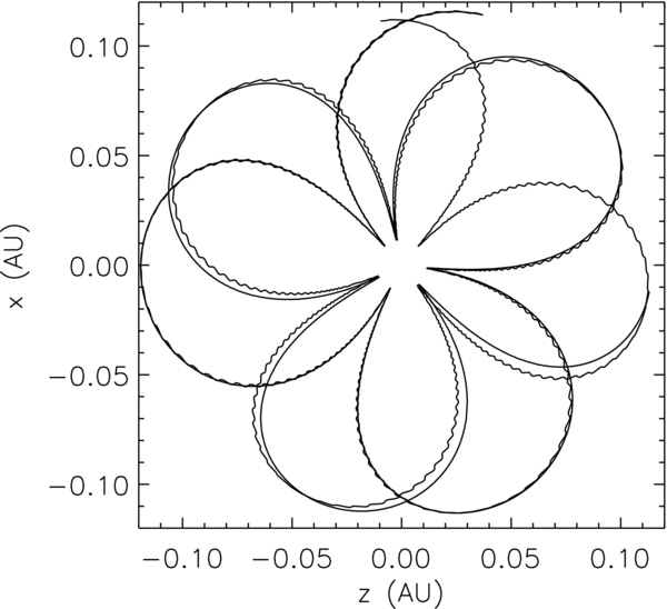
Figure 4. Two orbits of trapped grains (Q/m = 10−4 e/mp and Q/m = 10−5 e/mp) released from the same point (r = 0.12 AU from the Sun) at the same velocity. Note the similarity of the orbits, although for Q/m = 10−5 e/mp the Larmor oscillation is visible. The perihelia of the orbits are about 0.01 AU, the aphelia slowly decrease with time.
Download figure:
Standard image High-resolution imageA simple model for small grain dynamics near the Sun can be derived from the guiding center approximation. This approximation can be seen to be applicable for the nano dust grains near the Sun (r < 0.2 AU). The parallel velocity of the guiding center is given by (Northrop 1963)
where vG∥ is the guiding center velocity parallel to the magnetic field, g∥ the parallel component of the gravity force per unit mass acting on the grain,  is the plasma velocity perpendicular to
  , and μ ≡ v'2⊥/2B (v'⊥ = v⊥ − V⊥) the adiabatic invariant. In the expression for the perpendicular velocity of the guiding center, we shall neglect all terms dependent on the particles charge to mass ratio. Then,

In this approximation, the guiding center will stay on the same magnetic field line. Also, the colatitude θ and consequently a are constant in time.
All terms in Equation (7) can now be calculated explicitly. Instead of vG∥ ≡ ds/dt where s is the length along the magnetic field line, we shall use its radial projection v ≡ dr/dt with ds/dt = (1 + a2r2)1/2dr/dt. Equation (7) is equivalent to

where the dots denote time differentiation,
The first two terms in Equation (7) and in Equation (11) correspond, respectively, to the gravity and the magnetic mirror force. The last term is analogous to the centrifugal force acting on a particle restricted to motion along the rotating magnetic field line.
The system of Equations (9) and (10) can be studied in the (r, v) phase plane. The  line is given by v = 0. The
  line is given by
If W(r) becomes negative for some r, the  and
and  cross at two points, i.e., the fixed points of the system (Figure 5). The rightmost of the fixed points is of the saddle point type. The other is the spiral sink. The trajectories starting near the saddle point move either toward the sink (trapped particles) or escape to large r.
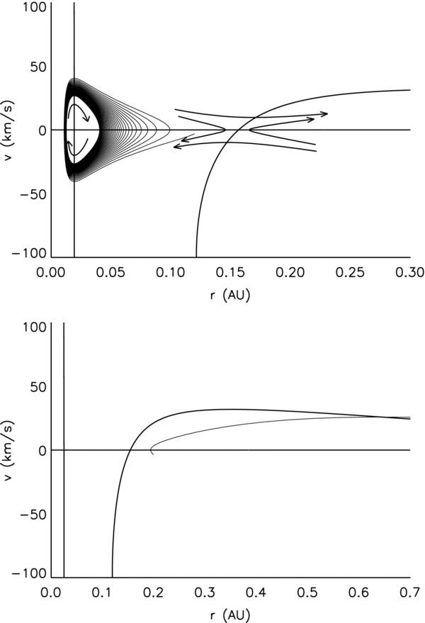
Figure 5. Phase plane for the model described by Equations (9) and (10). The parameters correspond to the particle released from the circular Keplerian orbit at the distance 0.12 AU from the Sun (left panel) and 0.2 AU from the Sun (right panel).
Download figure:
Standard image High-resolution imageIf W(r) stays positive for all r, there are no fixed points and all trajectories move ultimately to large r. This is what happens when the value of the adiabatic invariant is high so that the mirror force dominates over the gravity.
Figure 6 shows the extension of the trapped region for grains of different Q/m released from circular orbits. Observe that (1) the grains released at high heliolatitudes have a more extended trapped region in r and (2) for the grains released at small heliolatitude the trapped region decreases with increasing orbital inclination. Although these results were obtained from full simulations, they can be qualitatively explained within the present model: result (1) follows from the decrease in the magnitude of the centrifugal force term (∼sin θ) at large latitudes and result (2) is due to the increase of the adiabatic invariant (and therefore of the mirror force) because the value of |v⊥ − V⊥| for the grains released near the solar equator increases with the orbit inclination.
Figure 6. Limit of the trapped region for nano grains of different sizes (Q/m = 10−6 e/mp to 10−4 e/mp) released from circular orbits of different radius and inclination calculated using the full equations of motion. The maximum trapped r is shown. Thick lines correspond to the point of release situated at the maximum heliolatitude reached by the orbit (= the orbital inclination) and the thin lines to release near the solar equator.
Download figure:
Standard image High-resolution image
Figure 7. Perihelium distance and the time to perihelium for the first orbit of a trapped grain with Q/m = 10−4 e/mp released from the circular orbit at the distance R.
Download figure:
Standard image High-resolution imageIf the trapped grains orbits approach very close to the Sun, the probability of the grain destruction by evaporation or sputtering becomes high. The conditions required for a close approach can be easily found in the present model. Since the fixed points have v = 0, their positions are given by the roots of the equation W(r) = 0. Assuming that a2r2 ≪ 1 (which is satisfied in the trapped region), this becomes
The approximate values of the roots are

Equations (14) and (15) hold provided r2 ≪ r1. Note that the outer root r1 is determined by the ratio of the gravity to the centrifugal force, while the inner root r2 is related to the ratio of the mirror force to gravity.
Equation (15) suggests that the perihelium of the trapped grain orbits is correlated with the value of the adiabatic invariant μ. In terms of the release distance r0 and the release velocity v0:
so that high value of r2 and of the perihelium distance should be positively correlated with the value of (v0 − V)2⊥r20. This is confirmed by the results of our simulations using full equations of motion: the trapped orbits with high perihelia have also high (v0 − V)2⊥r20. The exception is the case of zero tilt current sheet, where some orbits with high (v0 − V)2⊥r20 have low perihelia: the model discussed in this section does not include the drifts along the current sheet.
A plot of the perihelium distances and time to perihelium for the nano dust released from the circular Keplerian orbits near the ecliptic is shown in Figure 7.
Note that a similar trapping mechanism would occur for the pick-up ions released from orbiting dust particles in the absence of pitch angle scattering. On the other hand, for the particles released from outward moving bodies (as can be the case for the nano dust split off the beta-meteoroids) the trapping would not take place.
6. SIMULATIONS FOR ENSEMBLES OF NANO DUST GRAINS
In addition to the individual orbits, we consider the ensembles of nano-sized grains, in order to estimate the average velocity components for the nano dust arriving at 1 AU. We assume that the nano dust grains originate from collisions between the larger grains from the circumsolar dust cloud and that their initial velocities are the same as the parent bodies. Specifically, we take the nano dust grains to start from circular Keplerian orbits. The parameters describing the orbit orientation (the inclination δ and the longitude of the ascending node ψ) and the initial position of the grain (the angle ϕ in the orbit plane counted from the ascending node direction) we take to be distributed uniformly within the limits appropriate to the circumsolar disk ((±)13 5 in latitude from solar equator plane) and the halo component ((±)85° in latitude, but confined to within 0.2 AU from the Sun). In calculating the averages, each trajectory is associated with the weight factor derived from the production rate of the nano dust grains by collisional fragmentation: the fragmentation rates are the same as in Mann & Czechowski (2005). Some results for the average velocity components (〈v〉) and the velocity dispersion (Δv = (〈v2〉 − 〈v〉2)1/2) for the nano dust arriving at 1 AU are collected in Table 1. Since we are interested in the STEREO observations, the results in Table 1 include only the grains arriving at 1 AU close to the ecliptic plane (within ± 13° from the solar equator). These grains make the fraction fobs ("observed") of all "escaping" (those reaching r > 0.9 AU) grains which make themselves the fraction fesc of all grains in the sample.
Table 1. Velocity Averages and Dispersions at 1 AU
| Q/m | fesc | fobs | 〈vr〉 | 〈vϕ〉 | 〈vθ〉 | 〈v〉 |
|---|---|---|---|---|---|---|
| (e/mp) | (km s−1) | (km s−1) | (km s−1) | (km s−1) | ||
| Tilt = 20°, focusing | ||||||
| 5 × 10⁻⁴ | 0.42 | 0.99 | 276 ± 40 | 140 ± 52 | 0.24 ± 56 | 316 ± 61 |
| 10−4 | 0.16 | 0.88 | 272 ± 39 | 134 ± 46 | 2.4 ± 57 | 308 ± 58 |
| 10−5 | 0.16 | 0.6 | 238 ± 46 | 104 ± 28 | −22 ± 64 | 269 ± 48 |
| 2 × 10⁻⁶ | 0.16 | 0.33 | 140 ± 33 | 53 ± 11 | 1.7 ± 88 | 174 ± 29 |
| 4 10−7 | 0.2 | 0.42 | 66 ± 21 | 26 ± 4 | −0.6 ± 50 | 87 ± 22 |
| Tilt = 20°, antifocusing | ||||||
| 10−4 | 0.16 | 0.87 | 273 ± 37 | 135 ± 46 | 7 ± 57 | 310 ± 57 |
| 10−5 | 0.16 | 0.45 | 257 ± 20 | 114 ± 18 | −36 ± 43 | 287 ± 24 |
| 2 × 10⁻⁶ | 0.17 | 0.003 | 86 ± 42 | 60 ± 8 | −106 ± 75 | 170 ± 27 |
| Tilt = 0°, focusing | ||||||
| 10−4 | 0.14 | 0.89 | 244 ± 71 | 118 ± 55 | −12 ± 55 | 277 ± 88 |
| 10−5 | 0.13 | 0.92 | 141 ± 74 | 55 ± 27 | 4 ± 52 | 161 ± 76 |
| Tilt = 0°, antifocusing | ||||||
| 10−4 | 0.18 | 0.87 | 273 ± 35 | 133 ± 43 | 14 ± 54 | 309 ± 53 |
| 10−5 | 0.18 | 0.32 | 256 ± 12 | 109 ± 5 | −37 ± 28 | 282 ± 12 |
Download table as: ASCIITypeset image
The averages are calculated as follows. For a quantity A(r0), (for example, a velocity component of a grain at the assumed final distance from the Sun; r0 denotes the initial point of the grain trajectory) we define a sum over the initial points:
where ρ(r) is the assumed production rate of the nano dust at the distance r. The averages are calculated as
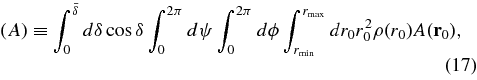
where the subscripts d and h stand for the disk and the halo. We use the values  = 135, rmin = 0.1 AU, and rmax = 1 AU for the disk, and
  = 85°, rmin = 0.02 AU, and rmax = 0.2 AU for the halo. The assumed nano dust production rates for the disk ρd(r) and for the halo ρh(r) are shown in Figure 8. The model used for calculating the rates is the same as in Mann & Czechowski (2005).

Figure 8. Assumed production rates of the grains in the 1–5 nm size range from collisional fragmentation of grains in the circumsolar dust cloud.
Download figure:
Standard image High-resolution imageThe results show that the velocity distribution of the nano dust grains arriving near Earth's orbit for the grains in the Q/m = 10−5–10−4 e/mp range is characterized by large radial speed (〈vr〉∼240–280 km s−1), higher by a factor of ∼2 than the azimuthal speed (vϕ∼100–140 km s−1); the 〈vθ〉 is much smaller (note that vθ is defined here to be positive when directed toward the solar equator). The nano grains move in the prograde direction: the retrograde motion would require much higher acceleration along the magnetic field direction. For Q/m larger than 10−4 e/mp, the final velocity is not significantly higher; on the other hand, for Q/m∼10−6 e/mp and smaller, the final velocity is much suppressed. The results do not depend strongly on the phase of the solar cycle, except for the case of low current sheet tilt.
The fraction of escaping nano dust fesc, which is of the order 0.1–0.2 of all nano dust grains in the sample, strongly depends on the assumed lower limit in r of the nano dust production region. It reflects the fact that the production of nano dust is most effective in the trapped region. The fraction of "observed" nano dust fobs (those of the escaping grains that arrive at 1 AU within ±13° from the solar equator) is typically high. However, for the Q/m = 2 × 10⁻⁶ grains in the antifocusing case, almost no grains satisfy the condition, opposite to the focusing case. This is in agreement with the results of Hamilton et al. who found that in the antifocusing field the grains escape away from the ecliptic. Their study was, however, restricted to the case of larger (>10 nm) grains.
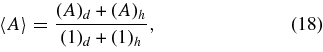
The results were also used to determine the distributions in inclination (defined as the angle between the velocity and the ecliptic plane) for the grains arriving at 1 AU. Figure 9 show these distributions for the grains (Q/m = 10−4 and 10−5 e/mp) arriving at 1 AU between 0° and 13° ecliptic latitude: the distributions for the negative latitudes (0° to −13°) are almost exactly symmetric under sign reversal of the inclination angle. The distribution for the smaller grains is more narrow and the peak occurs at lower inclination. The antifocusing case differs from the focusing case, but the difference is small. We also show (Figure 10) the plots of selected samples of the grain trajectories in the (r, y) plane, where y is the coordinate perpendicular to the ecliptic. The trajectories were selected from those starting from the dust disk area between 0.2 and 0.35 AU from the Sun, since the trajectories starting at larger distances would have smaller probabilities. Note the difference between Q/m = 10−4 and 10−5 e/mp grains, also reflected in the distributions in inclination.
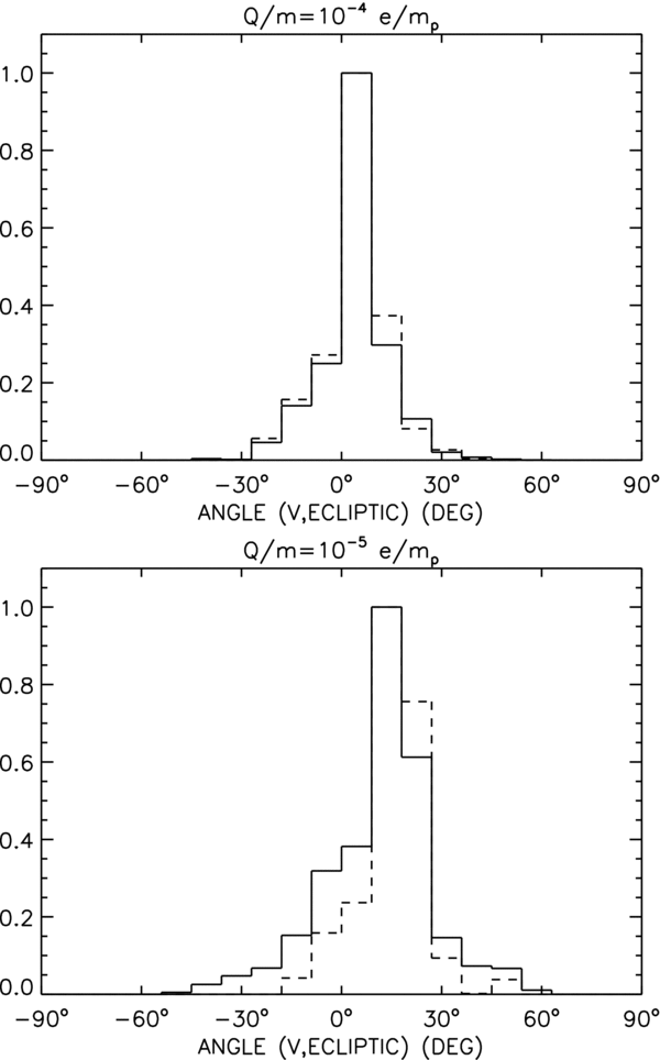
Figure 9. Distributions in inclination (defined as the angle between the particle velocity and the ecliptic plane) for the nano dust with Q/m = 10−4 e/mp and Q/m = 10−5 e/mp arriving at 1 AU within the range of ecliptic latitude from 0° to 13°. Positive inclination angle corresponds to the particles moving toward increasing ecliptic latitude. Current sheet tilt is 20°. The distributions for the focusing (defocusing) field case are shown by the solid (dashed) lines.
Download figure:
Standard image High-resolution image
Figure 10. Samples of trajectories of nano dust with Q/m = 10−4 e/mp and Q/m = 10−5 e/mp plotted in the (r, y) plane (y is the coordinate perpendicular to the ecliptic plane). The plots are for the focusing field configuration and current sheet tilt 20°. The initial points for the trajectories in the samples are in the y > 0, 0.2 < r < 0.35 region of the dust disk.
Download figure:
Standard image High-resolution imageBecause of numerous simplifications, our simulations are not meant to produce a fully realistic model of the velocity distribution of the nano dust grains at 1 AU. The model used for the production probabilities (Mann & Czechowski 2005) needs to be improved (the smallest fragment size was taken to be independent of the sizes of the colliding particles; also, the fragmentation rates were calculated using the same formulae for the catastrophic and for the cratering case). Also, the calculations assumed the same moment of release for all particles, so that the moment of arrival at 1 AU was different within the sample. However, the model includes the main features of the spatial distribution of the source of the nano dust expected from the models of the circumsolar dust cloud, and we consider it to be acceptable as a first approximation given the lack of observational data describing the inner solar system dust cloud.
7. DISCUSSION
7.1. Comparison to Previous Dynamics Calculations
Hamilton et al. (1996) have considered the dynamics of the dust grains with radii of 0.01–0.1 μm in the inner heliosphere. For this size range, the Lorentz force is important for the dynamics, while the effect of radiation pressure is not dominant. The model of the magnetic field used by Hamilton et al. was similar to ours (Parker field with fixed tilt heliospheric current sheet). The authors were interested in explaining the Ulysses observations of small grains at high ecliptic latitudes, beyond the zodiacal cloud. They have considered small samples of grains, with no weigh factors reflecting the production rates. The initial orbits of the grains were circular and uninclined, with the radii between 0.25 and 4.0 AU. They found that, in the "focusing" configuration, the small (<0.05 μm) grains escape to large distances with the trajectories staying near the ecliptic plane; the larger grains stay in bound orbits. In the defocusing configuration, the 0.1 μm grains escape to high latitudes; the authors note that the small grains in the defocusing configuration attain lower latitudes than the larger ones, which can be explained by the combined effect of gravitation-induced drift (size-independent, directed away from the ecliptic) and the radial acceleration (high for the small grains). This conclusion agrees with our results (see Table 1). For the grains with 0.15 μm radii (neglecting the radiation pressure effect), they found a region of bound orbits between 0.75 and 1.5 AU, while the grains released inward or outward of this region were found to escape.
An interesting comparison can be also made with the study of the pick-up ion dynamics by Luhmann (2003). Inward from 1 AU, the Larmor radii of the nano dust grains become small due to 1/r2 behavior of the magnetic field: in consequence, their dynamics shows similarities to the pick-up ions, at least in the approximation neglecting pitch-angle scattering as used by Luhmann. Luhmann observes that the ions picked up near the Sun (where the angle between the colar wind velocity and the magnetic field is small) attain velocities of the order of solar wind velocity, similar for the nano dust. On the other hand, the ions picked up at larger distances (solar wind velocity approximately perpendicular to magnetic field) reach double of the solar wind velocity. The orbits of the pick-up ions calculated by Luhmann illustrate how the retrograde motion (with trajectories similar to the Parker spiral) emerges for the ions with high initial radial velocities, higher than the solar wind velocity: for the nano dust such initial velocities are unlikely, so that the orbits cannot be retrograde.
The effect of Lorentz force on the orbits of larger grains (⩾1 μm) was considered by Morfill & Grün (1979). The Lorentz force is also important for deflection of the interstellar grains entering the heliosphere (Levy & Jokipii 1976; Landgraf 2000; Linde & Gombosi 2000; Czechowski & Mann 2003a, 2003b).
7.2. Comparison to Measurements Near 1 AU (STEREO and ISS)
Possible observations of the nano dust near 1 AU were reported from the International Space Station (ISS: cratering in the exposure foil; Carpenter et al. 2007) and from STEREO A and B spacecraft (voltage pulses; Meyer-Vernet et al. 2009a).
The ISS observations were done inside Earth's magnetosphere; the rigidity of high velocity nano dust grains is high enough (∼10 GV for Q/m = 10−4 e/mp grains moving at 300 km s−1) to be observed at the ISS. The estimated flux (Carpenter et al. 2007) of the nano dust is consistent with the interplanetary dust distribution.
The flux of nano dust was also estimated from the observations of voltage pulses by STEREO. According to Meyer-Vernet et al. (2009a; Equation (11)) the cumulative flux of the nano dust down to 10−20 kg mass is 0.03–5.0 m−2 s−1 (or 10 times less when averaged over all observing time). The authors assume m−5/6 behavior of the cumulative flux. The result is consistent with the ISS observations (within large uncertainty).
Here, we do not attempt a precise estimate of the flux of accelerated nano grains. The reason is that a realistic model of nano grains production still needs to be developed. Nevertheless, the production rates (Figure 8) can be used for a rough estimation. The flux of nano dust near the ecliptic at 1 AU is given approximately by the total nano dust production rate within 1 AU (the integral of the rates shown in Figure 8 over the source regions defined in Section 6) multiplied by the fractions fesc and fobs from Table 1 and divided over the area through which the dust trajectories were required to pass (at 0.9 AU from the Sun and within 13° from the ecliptic). The result for the flux of the nano dust in the 1–5 nm size range is ∼150.0 m−2 s−1 times fescfobs. Taking fescfobs = 0.15 gives then ∼ 22.5 m−2 s−1. This is equivalent to about 0.6 m−2 s−1 for the flux of >10 nm (> 10−20 kg) grains, assuming m−5/6 behavior. This result is within the limits following from the STEREO data.
7.3. Flux Variations
The voltage pulses observed by STEREO do not occur with uniform frequency but show (possibly seasonal) variation with time (Meyer-Vernet et al. 2009a) with some time periods apparently free of those events.
If the dust of sizes several micrometer and smaller belonging to the circumsolar dust cloud is indeed the major source of the nano dust, then it is unlikely that the nano dust production rate within Earth's orbit shows variations similar to those seen in STEREO data.
Although we do not have a detailed explanation of the time variation observed by STEREO, our model includes one feature that can be responsible for strong time variation of the nano dust flux at 1 AU.
Our calculations show that if the nano grains are produced as fragments of dust grains moving in approximately Keplerian orbits, then a majority of the produced nano grains may become trapped near the Sun. If so, the accelerated grains would form a minority (10%–20%) of all nano grains produced within 1 AU.
This conclusion may fit with the large variations in the nano dust flux observed by STEREO: a relatively small change in conditions in the region within 0.2 AU from the Sun (for example, interaction between different speed streams of the solar wind) may change the boundaries of the trapped region and lead to a large temporary increase in the number of accelerated grains. However, the question whether this mechanism can produce the variations observed by STEREO would have to be considered in a more detailed, time-dependent model.
Since the exact conditions of the dust detection with the plasma wave measurements are still subject to detailed studies, it is possible that the time variations suggested by the STEREO results are partly due to variations in the detection efficiency.
7.4. Nano Dust Beyond 1 AU
Although we did not do any large sample simulations for the nano dust at large distances from the Sun, we studied a small number of individual trajectories. We considered the release points near the ecliptic between 0.1 and 2.5 AU and followed the trajectories up to ∼100 AU. We found that the trajectories of the Q/m = 10−4–10−5 e/mp grains accelerated within 1 AU have high velocity values also beyond 1 AU. Also, the grains released from Keplerian orbits beyond 1 AU become accelerated and reach high velocity. The velocity attained at large distance in the focusing configuration is ∼400 km s−1, even higher than ∼300 km s−1 reached within 1 AU: some of the particles, crossing into the fast wind region, attain even higher velocities. The effect of the current sheet is strong: the velocities are higher for the nonfocusing configuration and reach ∼600–700 km s−1. The larger (Q/m = 10−6 e/mp) grains released in the focusing configuration close to the Sun keep at large distances the velocities they reached within 1 AU (100–150 km s−1) but those released at larger distances reach only ∼50 km s−1 or less. In the antifocusing field they reach 200 km s−1.
We conclude that once the particles are accelerated they would keep the high velocity on their trajectory toward the heliopause and leave the heliosphere without major interactions. Gas friction is negligible on the heliosphere size scale. A particle of 3 nm radius and the area 3 10−13 cm2 has a mass of the order of 105 proton masses. On the way from the vicinity of the Sun to the distance of 100 AU, it would collide with 45 H atoms (assuming the average H density 0.1 cm−3); the number of collisions with solar wind protons would be also small.
7.5. Jupiter Stream Particles
During the Ulysses flyby of Jupiter, the dust detector on board measured periodic collimated streams of dust particles emanating from the direction of Jupiter (Grün et al. 1992, 1993). Several sources and ejection mechanisms were discussed; all suggest that small dust particles are charged and accelerated in the Jovian magnetosphere with the flux being further modulated in the interplanetary magnetic field (Hamilton & Burns 1993; Horányi et al. 1993). The velocities of the particles and their masses are outside the calibration range of the instrument. Initial analyses suggested that the dust velocities are larger than 100 km s−1. However, considering continued Ulysses measurements and dust measurements onboard Galileo and Cassini in comparison with the trajectory estimates implies that the detected particles have sizes of the order of 10 nm and impact speeds of the order or 400 km s−1 (Zook et al. 1996; Graps et al. 2000).
To see whether the nano dust emitted from Jupiter magnetosphere can also be observed at 1 AU, we applied the single particle trajectory calculations to samples of particles with Q/m = 10−5–10−4 e/mp and found that particles that start with initial velocity of 400 km s−1 at the location of Jupiter and move radially away from the planet are in general deflected from their initial direction and turn anti-sunward. However, some of the particles with Q/m = 10−5 e/mp during the focusing configuration period were able to penetrate to short distance (1 AU) from the Sun. This was not possible during the non-focusing field periods. Smaller grains with Q/m = 10−4 e/mp did not penetrate to small distances in any case. Particles that were ejected from Jupiter with initial velocity 100 km s−1 were all deflected in solar downwind direction. Hence, from the dynamics point of view, the particles ejected from Jupiter could really be measured at 1 AU, if they leave the surrounding of the planet with a velocity ⩾ 400 km s−1.
However, the resulting flux at 1 AU is small. Krüger et al. (2006b) used the measurements of Jupiter stream particles from different spacecraft to determine the dust flux and the variation of the dust flux with distance from the planet. They found that the fluxes measured at the times when the streams occurred are consistent with a 1/r2 decrease of the flux with distance r from the planet. From their results, it follows that the flux at the distance of 4 AU from the planet is 2 × 10⁻⁴ m−2 s−1. The distance between Earth and Jupiter (and between STEREO and Jupiter) is always larger than 4 AU. Hence, the flux of the Jupiter stream particles at the location of the STEREO spacecraft is 2 orders of magnitude lower than the smallest value of the cumulative flux of dust with masses 10−20 kg derived from the STEREO measurements (0.03 m−2 s−1). The flux rates of interplanetary and interstellar dust detected onboard Ulysses are below those measured in the Jovian dust streams (Krüger et al. 2006a).
7.6. Dust Charges and Charge Fluctuations
Figure 11 shows the values of Q/m as a function of grain mass derived from calculated surface potentials for dust in the vicinity of the Sun (Mukai 1981) and near 1 AU (Kimura & Mann 1998). Values at 0.3 and 0.5 AU, for solar minimum and solar maximum periods are plotted, for the silicate and the graphite dust. The Q/m values do not vary much with distance, and variation between the solar minimum and solar maximum is within a factor of 3. The values of Q/m used in our simulations 10−4 and 10−5e/mp can be seen (using Q/m∼1/s2) to correspond approximately to dust radii s∼3 nm and 10 nm (silicate) and 2 nm and 7 nm (graphite), respectively. The charge and electric potential values for the 3 nm Q/m = 10−4 e/mp grain are ∼17 e and ∼8 V and for the 10 nm grain with Q/m = 10−5 e/mp ∼63 e and ∼9 V (assuming 2.5 g/cm3 mass density).

Figure 11. Charge to mass ratio used for the nano dust calculations in comparison to values derived from calculated surface potentials for dust in the vicinity of the Sun (Mukai 1981) and near 1 AU (Kimura & Mann 1998). Q/m vs. mass is plotted. The lines are extrapolations (using Q/m ∼ inverse square radius of the grain) of the values for 0.28 μm silicate dust (solid lines) at 1 AU and 0.332 μm graphite dust (dotted line) at 1 AU. For silicate, the two lines correspond to different solar wind conditions. The horizontal dashed lines correspond to Q/m = 10−4 e/mp and Q/m = 10−5 e/mp. The data points correspond to 1 and 10 nm dust particles at 0.3 and 0.5 AU for solar minimum and solar maximum—0.3 AU, solar minimum: triangles; 0.5 AU, solar minimum: diamonds; 0.3 AU, solar maximum: squares; and 0.5 AU, solar maximum: X. The mass values for the 1 and 10 nm silicate dust are higher than that for the graphite dust of the same size, so that the data points for silicate are to the right of those for graphite.
Download figure:
Standard image High-resolution imageAs noted before, the dynamics of the nano dust may be affected by charge fluctuations. The effect of charge fluctuation can be estimated from the ratio of the frequency of impacts leading to the variations in charge to the Larmor frequency of the grain. If the time between impacts is much less than the Larmor rotation time, the effect of charge fluctuation would average out within one Larmor rotation time. The charge of the grain can be then approximately replaced by the average value.
Whether such approximation is possible for the case we are considering (grains with Q/m = 10−4–10−5 e/mp in the region inward from 1 AU) depends on the exact size of these grains. We estimate the charge fluctuation frequency from the electron impact rate. Since the equilibrium charge on the grains in the region considered is positive, we can use the impact rate for zero surface potential and treat the result as a lower limit (the electron impact frequency for a charged grain will be higher). We assume average electron temperature to be 2 × 10⁵ K at 0.5 AU and 5 × 10⁵ K at 0.1 AU and the dust effective cross section to be πs2. For the grains with radius s = 1 nm with Q/m = 10−4e/mp, we estimate the ratio (time between electron impacts)/(Larmor rotation time) to be 0.08 at 0.1 AU and 0.15 at 0.5 AU. On the other hand, if the same Q/m would be applicable to 3 nm grains (as suggested by Figure 11), the ratio becomes smaller by a factor of 9 and the approximation of neglecting the charge fluctuations is even better justified. The approximation becomes better for smaller Q/m and/or larger sizes of the grains.
7.7. Dust Destruction
In the inner solar system, the nano dust is subject to destruction, in particular by sputtering and sublimation.
The majority of dust particles is expected to sublimate within a sublimation zone around the Sun. The exact distance of sublimation depends on the sublimation rate of the given material as a function of temperature and on the light scattering properties that determine the dust temperature at a given distance from the Sun. The dust sublimation rate increases quickly when a critical temperature is reached and then the dust lifetime is shorter than the orbital period of dust in Keplerian orbit—this is usually assumed as the dust-free zone.
Mann et al. (2004) compiled different estimates of the dust sublimation zones. The values listed in Table II of this reference show that in some cases dust particles may approach the Sun as close as a distance of 2 solar radii. A likely value of the extension of the dust-free zone around the Sun, that agrees with dust composition models as well as with some observational results, is that a large fraction of the dust comes near the Sun inward to 4 solar radii (Mann et al. 2004).
Figure 5 of Krivov et al. (1998) illustrates the sublimation history of typical dust grains near the Sun. The compact silicate grains commence sublimation at ∼5 R☉. Table I of Krivov et al. (1998) gives the value of 0.01 year for the sublimation lifetime of the 0.1 μm silicate compact grain. Assuming that the sublimation lifetime is approximately proportional to the grain size, the 10 nm nano dust grain in the region within 5 R☉ from the Sun would have the sublimation lifetime of 0.001 year, which is much less than the time needed to reach the perihelium from the release distance (Figure 7). The trapped nano grains with the perihelions less than 5 R☉ will be therefore destroyed by sublimation within one orbit.
Note that most of the discussion of the sublimation properties was done for the dust in the size range of 0.1–1 μm. For the nano dust, the real sublimation rate may be different.
We have also estimated the survival probabilities for sputtering using the mass-loss rates given by Mukai & Schwehm (1981). The result is that sputtering has no significant effect on escaping grains (Figure 12). For trapped grains, the calculated destruction probability per orbit for average solar wind conditions is 0.002 for the 10 nm grain released from a low inclination circular orbit at 0.03 AU and 0.04 for the grain released at 0.16 AU, assuming the mass-loss rate for obsidian. The grains released near the outer boundary of the trapped region move in orbits with very low perihelion value, which increases the destruction rate. Note, however, that our model becomes invalid at small heliocentric distances, where the magnetic field deviates from the Parker spiral.
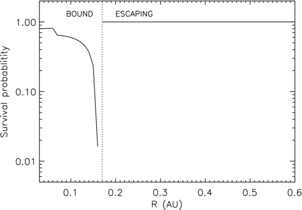
Figure 12. Survival probability against sputtering of nano dust with initial size 10 nm released from low inclination Keplerian orbits. The probabilities are derived from sputtering lifetimes of obsidian particles calculated by Mukai and Schwehm (1981) for the average solar wind case. Sputtering survival probabilities are shown against the initial release distance R. For bound orbits the survival probability after 100 orbits is shown. For escaping particles the probability is for survival until 0.9 AU.
Download figure:
Standard image High-resolution image
Mukai & Schwehm (1981) have also considered the case of high flux (1010 cm−2 s−1), high He content (25%) plasma flow (parameters taken from Table 13.1 in Svalgaard 1977). For this extreme case, they found the mass-loss rate due to sputtering to be higher by 2 orders of magnitude compared to the average solar wind. The effect on escaping nano dust would in this case still be small, but the trapped grains would typically be destroyed within one orbit. A consistent treatment would require calculation of the dust orbits in the highly perturbed solar wind and we do not attempt it here.
We note that data about sputtering of typical cosmic dust materials are rare and there are no data describing sputtering of nano dust. Sputtering due to the higher energy particles becomes important during solar flares.
8. SUMMARY
We have studied the dynamics of nano-sized grains in a simple model of the solar magnetic field and plasma flow, concentrating on the region within 1 AU from the Sun.
Assuming that the nano grains start with Keplerian initial velocities, there is a region near the Sun (within about 0.15 AU, but wider at higher heliolatitudes) where the produced grains would be trapped. A typical trapped orbit has a small perihelium distance and enters the region where the magnetic field deviates from the Parker model on which our calculations are based. Our treatment of the trapped nano grains is therefore incomplete. However, it leads to a very simple description that helps to understand the trapping qualitatively.
The grains created outside this region are accelerated to high velocities (300 km s−1) as required to explain STEREO measurements, and escape to large distances. These conclusions apply to the grains with charge to mass ratio Q/m not much less than 10−5 e/mp (grain radii ∼10 nm and smaller). Because the density of the circumsolar dust cloud increases toward the Sun, the fraction of the accelerated grains is only about 10%–20% of all nano grains produced within 1 AU.
We have assumed that the charge to mass ratio of the grain is constant in time. In reality, the equilibrium charge on the grain would vary along the trajectory. The effect of this variation on our results would probably be small because of approximate Q/m-independence of the average trajectories. On the other hand, charge fluctuations may be important, at least for the smallest (∼1 nm) grains.
Our model permits only a crude estimation of the nano dust flux at 1 AU. The result is equivalent to about 0.6 m−2 s−1 for >10 nm grains, which is consistent with the flux measured by STEREO (0.03–5.0 m−2 s−1 cumulative flux of the dust with mass > 10−20 kg: Meyer-Vernet et al. 2009a). We do not have a detailed explanation of the large amplitude flux variations observed by STEREO but we note that a relatively small perturbation of the trapped nano dust may cause sudden increase in the escaping nano dust flux.
We made very simplified estimations of the survival probability of the nano dust against the sublimation and sputtering. Sublimation destroys the trapped grains typically within one orbit, provided that the perihelium is within the sublimation zone (within ∼5 solar radii from the Sun). The sputtering causes no significant loss of the escaping nano dust within 1 AU. For trapped dust, the highest destruction probability occurs for the grains released near the outer boundary of the trapped region (destruction after 25 orbits for a 10 nm grain released at 0.16 AU) because the orbits have then a particularly low perihelium value. The destruction rate rises sharply for high flux, high He content plasma streams.
Most of our results were obtained assuming that the nano dust is released from larger dust that moves in circular or low eccentricity orbits. However, a fraction of the nano dust can be generated by fragmentation of beta meteoroids, which are themselves accelerated by the radiation pressure. In this case, some of the nano grains would start with high outward directed initial velocities. Since the present work is based on a very simplified model of collisional fragmentation, we did not study this possibility in detail, except for calculation of some individual orbits. The results suggest that there is no trapped region for such nano grains.
This work was supported by the Polish Ministry of Science and Higher Education grants 4T12E 002 30 and N NS-1260-11-09. Parts of this work were also supported by the German Aerospace Center DLR (Deutsches Zentrum fur Luft- und Raumfahrt) under project RD-RX /50QP 0403 and by the Belgian Solar Terrestrial Center of Excellence.