


Abstract
Significant advancements have been made towards exploitation of naturally available molecular motors and their associated cytoskeletal filaments in nanotechnological applications. For instance, myosin motors and actin filaments from muscle have been used with the aims to establish new approaches in biosensing and network-based biocomputation. The basis for these developments is a version of the in vitro motility assay (IVMA) where surface-adsorbed myosin motors propel the actin filaments along suitably derivatized nano-scale channels on nanostructured chips. These chips are generally assembled into custom-made microfluidic flow cells. For effective applications, particularly in biocomputation, it is important to appreciably prolong function of the biological system. Here, we systematically investigated potentially critical factors necessary to achieve this, such as biocompatibility of different components of the flow cell, the degree of air exposure, assay solution composition and nanofabrication methods. After optimizing these factors we prolonged the function of actin and myosin in nanodevices for biocomputation from <20 min to >60 min. In addition, we demonstrated that further optimizations could increase motility run times to >20 h. Of great importance for the latter development was a switch of glucose oxidase in the chemical oxygen scavenger system (glucose oxidase–glucose–catalase) to pyranose oxidase, combined with the use of blocking actin (non-fluorescent filaments that block dead motors). To allow effective testing of these approaches we adapted commercially available microfluidic channel slides, for the first time demonstrating their usefulness in the IVMA. As part of our study, we also demonstrate that myosin motor fragments can be stored at −80 °C for more than 10 years before use for nanotechnological purposes. This extended shelf-life is important for the sustainability of network-based biocomputation.
Export citation and abstract BibTeX RIS

Original content from this work may be used under the terms of the Creative Commons Attribution 4.0 licence. Any further distribution of this work must maintain attribution to the author(s) and the title of the work, journal citation and DOI.
1. Introduction
In recent years, appreciable progress has been made in nanotechnology to understand and harness the potential of miniaturized molecular machines of either synthetic, hybrid or biological origin [1–7]. Of particular interest in this context are the biological molecular motors which are specialized enzymes that convert chemical energy in the form of high-energy phosphates (adenosine triphosphate; ATP), into physical work, such as intracellular transportation of cargoes and generation of cell motion. The myosins, such as myosin II with central roles in cell motility including muscle contraction, constitute one important superfamily of the biological molecular motors that walk along or propel actin filaments.
In numerous studies, actin-based myosin motors have been interfaced with lithographically produced micro- and nanostructures to produce novel nanostructured materials and nanodevices for diagnostics, biosensing, sorting, nanoseparation and, most recently, biocomputation [1–5]. Critical for these applications has been the use of electron beam lithography to produce nanoscale channels in polymer resist layers on SiO2 to physically confine actomyosin function [3, 4, 8–11]. Further chemical confinement has been achieved by functionalizing the SiO2 channel floors with trimethylchlorosilane (TMCS) to allow adsorption of motility-promoting myosin II motor fragments (heavy meromyosin; HMM). This approach was developed from standard in vitro motility assays (IVMAs) [12, 13], where actin propulsion by surface adsorbed myosin motor fragments was observed on flat, non-patterned surfaces instead of being precisely guided along nano-sized channels [10].
IVMAs are often used as parts of functional studies in fundamental research or to demonstrate the function of proof-of-concept nanodevices, where a statistically sufficient amount of data can be collected within a few minutes (<10 min) [4, 14]. In contrast, in larger-scale fundamental research and in applications where the motors are interfaced with nanostructures, data collection requires appreciably more time. This includes needs for use in high-throughput/high-content screening [15–18], practically useful biosensing and diagnostics devices [4, 5, 19] but, most significantly, upscaling of network-based computation [3]. In the latter instances, prolonged operation is essential to solve large, otherwise intractable mathematical problems. It would be advantageous if assay prolongation can be achieved by simple means without complex custom-built inert chamber systems [20] or specific methods for protein expression [21, 22]. Furthermore, it would be beneficial to use approaches that work with different motor types.
Here, we systematically investigate a range of approaches for achieving prolonged and high-quality motor filament function in nano devices with particular emphasis on biocomputation. The studies cover a number of optimisation steps that will be critical to implement in future network-based biocomputation devices, including changes to (1) the solution compositions, (2) the assembly of the motility assay flow cell and (3) the nanofabrication process.
2. Results and discussion
Below we consider several key improvements and optimizations that each will greatly benefit use of the actin–myosin II motor system and potentially other molecular motor—filament systems in nanotechnological applications, particularly biocomputation.
2.1. Optimizing flow cell assembly
Nanostructured chips for motor-driven nanodevices are usually fabricated in non-transparent material such as Si, necessitating observation of motility through the flow cell (figure 1(a)). This is challenging because high-magnification objectives typically have a short working distance (∼ 0.2 mm) and the standard double-sided tape (3M-Scotch) that we use as a flow-cell spacer for conventional IVMA experiments is 0.1 mm thick, adding to the 0.1 mm thickness of the underlying coverslip (No. 0) (cf table S.1 for details (https://stacks.iop.org/NJP/23/085005/mmedia)). Therefore, when observing a nanostructured surface through the flow cell, the spacer needs to be substituted by a thinner variant. We initially used a thinner double sided tape (3M-467MP, thickness 0.06 mm) that seemed to work well. However, we consistently noted shorter run times than for conventional glass flow cells using the standard tape spacer. Initially, we attributed this finding to toxic effects in the nanostructures. A systematic comparison of motility (figure 1(b)), using standard glass-based flow cells, revealed appreciably longer motility run times when using the standard tape (>60 min) or Parafilm (>60 min), as compared to using the thin tape (<20 min). These findings suggest that the thin tape has a toxic effect on the motor system. Notably, this toxicity was observed throughout the entire flow cell despite the small contact area between the tape and the assay solution, showing that the toxic component is dissolved in the assay solution.
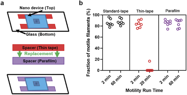
Figure 1. Spacer compatibility with actomyosin motility. (a) Schematic of assembled flow cell replaced with Parafilm spacer. (b) Fraction of motile filaments vs motility assay duration using different spacers on glass TMCS (temperature, 25 °C–26 °C). Note that the short motility run times are seen with the thin tape compared to standard-tape and Parafilm. In (b), seven different flow cell region of interest were analysed for each condition distributed over three different experimental occasions for thin tape, four different occasions for standard tape and three different occasions for Parafilm. Flow cells constructed using 18 × 18 mm2 top cover-slips (flow cell volume ∼ 20 μl).
Download figure:
Standard image High-resolution imageAs a replacement spacer we used flexible Parafilm (figure 1(a)). This is a sealing film, composed of paraffin wax and polyolefin that is commonly known for its non-toxic properties. It has also previously been employed as a spacer in flow cells for kinesin-microtubule motility assays, including nanodevice applications [24, 25]. Controlled stretch of heated Parafilm strips transformed them into suitable spacers with similar (60 μm) or lower thickness than the thin tape mentioned above, but without any evidence for toxic effects.
To summarize, the results in this section demonstrate the importance of carefully selecting the appropriate spacer for motility assay flow cells. Just selecting any thin tape does not work despite the small contact area between the tape and the assay solution, reflecting the appreciable sensitivity of the myosin motor system to toxicities. More generally, the finding emphasizes the importance to consider that the motility assay quality and longevity may be severely affected by unexpected factors unrelated to e.g. nanofabrication approaches. However, also the nanofabrication process (see further below) needs to be considered in this context as it has generally been developed for use in electronics and not in a liquid environment.
2.2. Preventing detrimental effects of dissolved oxygen
Despite the development of non-toxic spacers, we noted a decay in motility for observation periods longer than 60 min. We hypothesized that this was due to continuous air exposure at the entrances of the flow cell, despite these being reduced in size by the thinner spacers. Such effects may be particularly severe when using nanodevices, e.g. in biocomputation, with generally small surface area (10 × 8 mm2) compared to regular glass coverslips (18 × 18 mm2). This hypothesis was corroborated by experiments where flow cells were either open or sealed using silicon vacuum grease. The flow cells in these experiments had standard glass floors while the top coverslip roof was similar in size to that of standard nanodevices (figure 2(a)). Upon sealing of the open ends of the flow cell, motility was maintained for more than 60 min (figures 2(b) and (c)). Similarly, sealing of the flow cells showed a favourable effect on motility run-time on nanostructured surfaces, in particular within larger open areas known as 'loading zones', which capture filaments from solution and funnel them towards nanoscale channel networks.
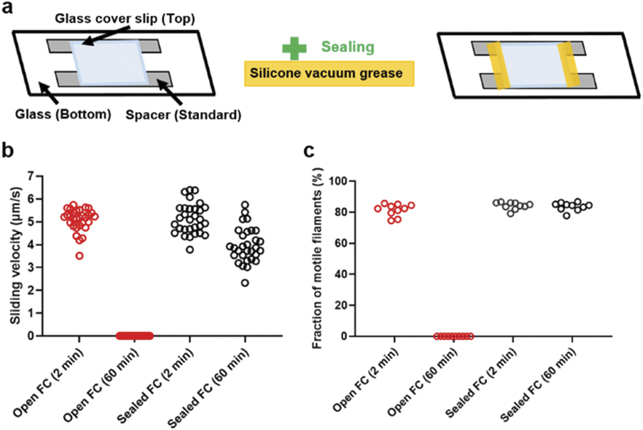
Figure 2. Comparison of open and sealed flow cell chamber on a glass TMCS with smaller (∼ 10 × 8 mm2) top glass roof and standard spacer. (a) Schematic of assembled flow cell with standard spacer, open (in left) and sealed (in right). (b) and (c) Sliding velocity and fraction of motile filaments showing no motility after 60 min with open flow cell compared to stable motility with sealed flow cell (temperature, 25 °C–26 °C). In (b), 30 filaments were analysed for each condition and each time point, distributed over two different experimental occasions for both conditions. Whereas the velocity reduction with time was dramatically higher for the open than for the sealed flow cells the reduction was statistically significant also in the latter case (p < 0.0001; unpaired t-test). We attribute the effect to remaining O2-leakage into the flow-cell and reduction of pH due to effect of oxygen scavenger mixture (see further below). In (c), ten different flow cell regions of interest were analysed for each condition and each time point, distributed over two different experimental occasions for both conditions. Flow cells constructed using top cover-slips with size similar to biocomputation chips (flow cell volume < 10 μl).
Download figure:
Standard image High-resolution imageThe favourable effects of sealing the flow cell reflect key detrimental effects of air access. First, oxygen dissolved in the assay and storage solutions, would cause oxidation of both HMM and actin. Second, the conventionally used oxygen scavenger cocktail, glucose oxidase + glucose + catalase (GOC) causes accumulation of an acidic product (see further below) when oxygen is consumed. In view of the dramatic effects of flow-cell-sealing (figure 2(b)), we decided to take more painstaking care than usual to minimize oxygen contamination. Thus, in preparation of the wash buffer and the assay buffer, the main constituent (a low ionic strength solution; LISS) was de-gassed for at least 40 min to reduce the amount of dissolved oxygen (figure 3(a)). Additionally, storage vials for assay solutions were filled with nitrogen gas (N2), followed by wrapping Parafilm around the cap to provide extra sealing (figure 3(a)). Furthermore, during the experiment the assay buffer was transferred to a 1 ml syringe supplied with a narrow cannula to reduce oxygen entry during storage [23]. The syringe was also wrapped in aluminium foil to reduce the risk of temperature changes [24] and to prevent exposing light sensitive components such as catalase [25] throughout the experiment (figure 3(a)). We also introduced 'blocking-actin', which is an alternate approach to affinity purification for the improvement of function and stability in the IVMA [26]. 'Blocking-actin' refers to non-fluorescent actin filaments which are pre-added to bind to non-functional, 'dead', HMM motor heads on the motility assay surface (i.e. ATP insensitive). When the solution is washed with magnesium-adenosine-triphosphate (MgATP), the motility promoting heads release the non-fluorescent actin filaments while the dead heads stay bound. Thereby, primarily active heads will be able to bind to fluorescent actin which increases the signal-to-noise ratio and prevents channel blockage. Overall, by taking these precautions to optimize the flow cell assembly and counteract detrimental effects of dissolved oxygen, we were able to observe good motility for at least 180 min in our standard flow cells based on TMCS derivatized glass cover slips (figures 4(a) and (b)). Possibilities for further improvements are considered below.

Figure 3. Motility buffer preparation setup, storage and assembly of flow cell for nanodevice. (a) Schematic of step-wise handling of the buffers, starting from degassing (left), transfer of buffers to tubes with Parafilm wrapping (middle) and transfer of assay buffer to a syringe (right) wrapped with Parafilm and aluminium foil. (b) Schematic of the flow cell assembly with nanodevices, showing replacement of spacer and addition of sealing.
Download figure:
Standard image High-resolution image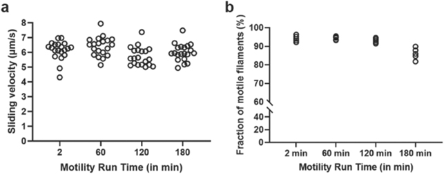
Figure 4. Motility on TMCS derivatized glass with optimized flow cell assembly, use of blocking actin and sealing of the flow cell as well as prevention of detrimental effects of dissolved oxygen by optimized solution preparation (see figure 3). (a) Sliding velocity remains similar at all time points tested (temperature, 25 °C – 26 °C). (b) The fraction of motile filaments remains similar until 120 min, but tends to be lower after 180 min (temperature, 25 °C – 26 °C). In (a), 20 filaments were analysed for each time point, distributed over two different experimental occasions. In (b), five different flow cell regions of interest were analysed for each time point, distributed over two different experimental occasions. Flow cells constructed using 18 × 18 mm2 top cover-slips (flow cell volume ∼ 20 μl).
Download figure:
Standard image High-resolution image2.3. Nanofabrication affecting motility
The fabrication of nanostructures is another factor that may compromise molecular-motor driven motility. We frequently observed poor motility within nanoscale channels despite high-quality motor function with extensive longevity, in the larger, micrometer scale loading zones on the same chip. This may be caused by insufficient silanization on the floors of the nanoscale channels, either due to inadequate removal of residual polymer, or because of problems with the actual silanization procedure. These effects may not appear in the larger, micrometer scale areas. In the loading zones, an effective silanization can be verified e.g. by different approaches for estimating the contact angle [27]. This is not readily achieved in the nanoscale channels. Instead, a guide to the proper functionalization of these channels is to investigate the degree of attachment of functional HMM molecules. In our experiments, the network region of the nanodevice was mapped by pre-incubation with HMM, where fluorescent Alexa-nucleotide was locked to the active site in the presence of vanadate [28]. Using this approach, the HMM motor density on the surface appeared similar on average in three major regions of interest, i.e. inside nano channels, micro channels and the loading zones of the network (figures 5(a)–(d)). Interestingly, however, we observed spatial non-uniformities in motor deposition in some network regions (figures 5(f) and (g)). Such regions would be expected to exhibit defect motility, leading to events like actin filament detachment with filaments escaping from the fabricated network region. Particularly, it is important to note that one such defect area in a nanoscale channel would eliminate all motility downstream.
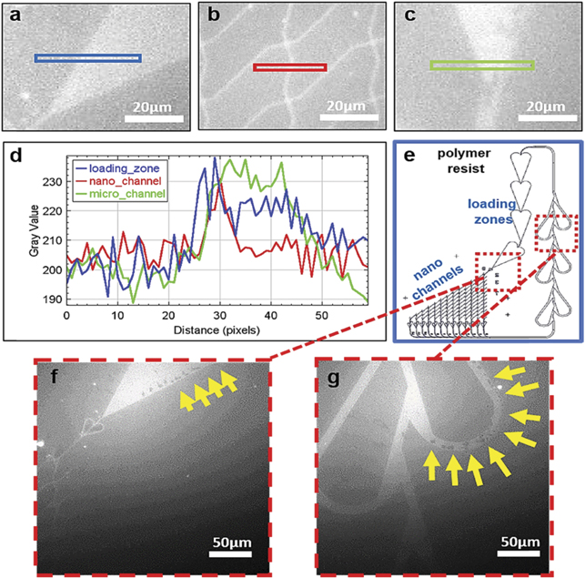
Figure 5. Fluorescence labelling of HMM on different parts of a biocomputation nanodevice using fluorescent Alexa-647 nucleotide in presence of vanadate. (a) Loading zone in the nanodevice. (b) Nano channel in the nanodevice. (c) Micro channel in the nanodevice. (d) Intensity profile plot, corresponding to equally coloured boxes in panels (a)–(c), showing similar distribution of HMM throughout the nanodevice. (e) Representation of a biocomputation network. (f) and (g) Arrows point to regions without myosin binding.
Download figure:
Standard image High-resolution imageTo circumvent the low motility run-time in nanodevices, a few important factors in the device fabrication procedure were investigated. Whereas we have produced functional nanodevices of a type similar to that described here for more than a decade now [10], there are continuous changes in the fabrication that are difficult to control for various reasons. These include new equipment with new properties, new material batches, e.g. resist polymers and silanes and, finally, changes in processing steps due to changed lab routines, general environment and personnel. In this context, we hypothesized that the following aspects of the fabrication procedure are important and might have been subject to changes outside full control: method of oxide layer formation, polymer resist type, electron beam lithography (EBL) exposure dose and acceleration voltage, EBL development, chip dicing, plasma etching and silanization procedures.
In order to test these hypotheses, we examined each variable individually. We first found that a number of steps had no critical effects on the quality and longevity of motility. These include: (1) SiO2 layer fabrication method—both atomic layer deposition and thermal oxidation of Si into SiO2 gave similar motility run-times, (2) polymer resist type - similar longevity was observed for the high-resolution polymer resist CSAR62 (ARP-6200) [9] and for poly-methyl methacrylate (PMMA), (3) EBL exposure dose and acceleration voltage, (4) polymer development after cross-linking—no changes in longevity were seen when methyl isobutyl ketone: isopropyl alcohol (MIBK: IPA) was replaced with amyl acetate-5. In this connection, it should be mentioned that both CSAR62 and PMMA have previously been shown to be useful for their present roles in nanodevices [8, 9] and it is important to emphasize that not just any polymer resist can be used [1, 9, 29].
Whereas the above-mentioned steps were of no apparent significance we noted that the timing of the chip dicing was important. We found that dicing of the developed devices would generate debris in the channels and junctions (figures 6(a) and (b)). It was not possible to effectively remove the debris from the device via plasma etching, indicating that the debris consists of inorganic material. The distribution of the debris seems to correspond to the defects in HMM adsorption observed in the fluorescence micrographs of HMM density (figures 5(f) and (g)). Importantly, we were able to solve this issue by dicing before developing the resist. The resist layer then works as a protective layer and prevents the debris from landing in the channels (figure 6(d)).
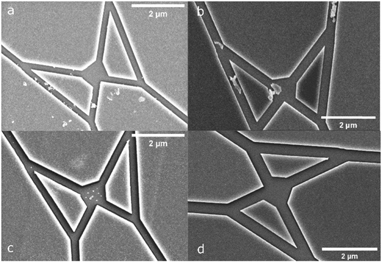
Figure 6. SEM images of fabricated network with nano channels. (a) Nanodevice (split junction in biocomputation device [3]) developed first as a whole wafer and then diced into individual chips for IVMAs. (b) Nanodevice in (a), after 60 s of plasma etching. Note, the debris remained after the etching process indicating inorganic residues, i.e. presumably particles of silicon dioxide. (c) Nanodevice first diced into individual chip followed by development steps. (d) Nanodevice shown in (c), after 60 s of plasma etching where no residues could be observed.
Download figure:
Standard image High-resolution imageBeyond the chip dicing, we studied the plasma etching procedure with aims to further optimize the motility. This step normally follows the EBL development and has two main purposes. The first is to remove resist remnants on the channel floors for subsequent effective silanization. The second is to modify the surrounding resist layer surfaces and channel walls to make these negatively charged, in order to prevent HMM motor function outside the channel floors while introducing OH- groups to the SiO2 surface [30, 31].
To realize the first aim, optimization of the plasma etching time and TMCS silanization time is demonstrated by experiments where etching time was increased from 15 s to 45 s and silanization time from 30 min to 90 min. Both these changes substantially improved motility quality in the loading zones (figure 7). We attribute this finding to more effective removal of organic residues on the exposed SiO2 areas of the loading zones, opening for more effective subsequent silanization. In parallel, longer silanization time ensures proper functionalization of the surfaces of the loading zones. Together, prolonged etching and silanization significantly improved the HMM attachment (as suggested by observed actin filament motility) and made it more evenly distributed within the loading zones as indicated by the actin–myosin motility distribution (figure 7). However, despite the above improvements, with increased etching and silanization times, there was frequently still no motility in the nano channels (cf table S.2).
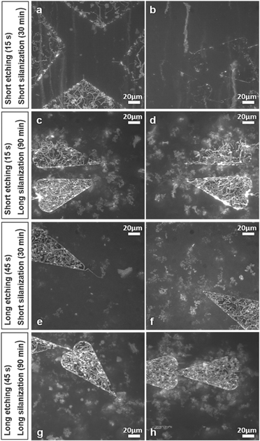
Figure 7. Function of actin–myosin motility under different fabrication conditions). (a) and (b) Nanodevices for biocomputation treated with short plasma etching (15 s) along with short TMCS silanization (30 min). (c) and (d) Nanodevices treated with short plasma etching (15 s) along with long TMCS silanization (90 min). (e) and (f) Nanodevices treated with long plasma etching (45 s) along with short TMCS silanization (30 min). (g) and (h) Nanodevices treated with long plasma etching (45 s) along with long TMCS silanization (90 min). Note, (g) and (h) show more consistent and evenly distributed motility in the loading zones of the nanodevices compared to (a)–(f). All images are generated as maximum projection stack of 100 frames acquired 2 min after start of the assay using the software ImageJ.
Download figure:
Standard image High-resolution imageWe further investigated the plasma etching procedure as it is crucial to remove all resist residues and organic contaminants to enable an effective silanization but also to modify the resist surface characteristics. We hypothesized that narrow channels (100–200 nm wide compared to loading zone dimensions >1 μm wide) may compromise the effectivity of the plasma etching that had, so far (figures 8(a)–(c)), been achieved using an anisotropic system (NanoEtcher). In the applied system (cf materials and methods), the plasma is generated by radio frequency power (RF) between parallel plates [32]. The plasma is then biased and expected to unidirectionally bombard the device surface (on top of one plate), resulting in a significant higher etching rate at the bottom of the channel compared to the sidewalls. Such system could make the HMM molecules adsorb on the channel walls in potentially undesirable configurations due to the insufficient side etching. This assumption is probably sufficient to explain the poor function in narrow channels (figures 8(b) and (c)) because the filaments usually move along the wall in such channels [10, 31]. Based on this reasoning, we switched to isotropic plasma etching (Asher- PlasmaPreen, see materials and methods), with the aim to etch the floor and sidewalls of the nano channels at the same rate (figures 8(d)–(f)). In the system, the plasma was generated in the vacuum chamber via the excitation of microwave energy. A Faraday cage is introduced to block the electromagnetic field and provide the isotropic plasma. After using the isotropic plasma etching, we observed similar motility in narrow channels and loading zones, making the whole network perform as desired for more than 1 h (figure 9). This was also the longest time that motility in the network was observed.
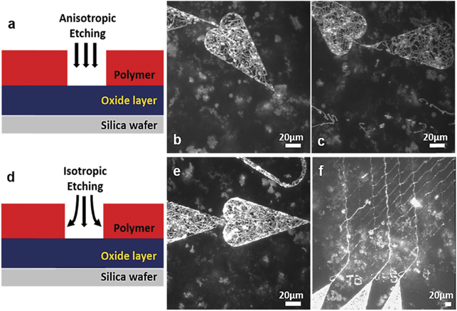
Figure 8. Isotropic vs anisotropic etching of nano channels in biocomputation network designed to solve a small-scale proof of principle NP-complete problem. (a) Anisotropic plasma etching treats the target surface in a unidirectional manner. (b) and (c) Nanodevices with motility in loading zones but not in nano-channels following anisotropic etching but with use of long (optimized) etching and silanization times (see figure 7). (d) Isotropic plasma etching treats the target surface in more distributed manner reaching the deep edges and walls in the nano channels. (e) and (f) Nanodevices with improved motility both in loading zones and-nano channels following isotropic etching. All images are generated as maximum projection stack of 100 frames acquired 2 min after start of the assay using the software ImageJ. Panel (b), is identical to the one in main figure 7(g).
Download figure:
Standard image High-resolution image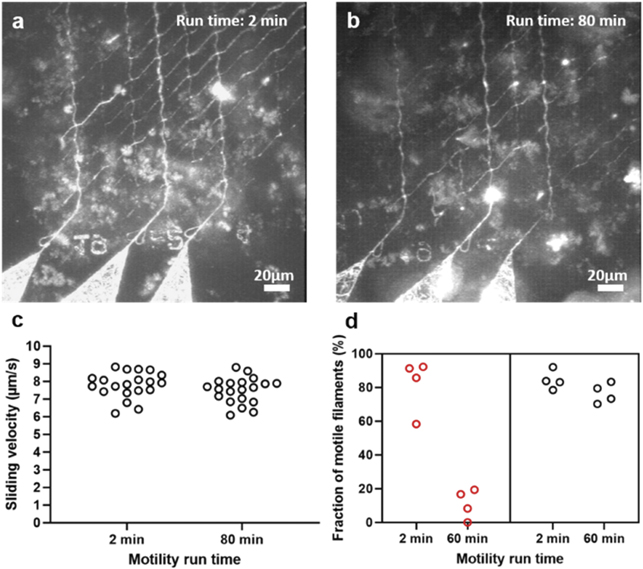
Figure 9. Motility in biocomputation nano network under fully optimized conditions including switch to isotropic etching conditions. (a) Function of actin–myosin at 2 min. (b) Function of actin–myosin at 80 min. (c) Sliding velocity in nano channels remained similar after 80 min of run time (temperature, 25 °C–26 °C). (d) The fraction of motile filaments before optimizations (red) and after applied optimizations (black) (temperature, 25 °C–26 °C) (cf figure S.1). Images (a) and (b), are generated as maximum projection stacks of 100 frames acquired 2 min after and 80 min after start of the assay using the software ImageJ respectively. In (c), 20 filaments were analysed for each time point in the nano channel networks showed in (a) and (b). In (d), four loading zones were analysed, distributed over four different experimental occasions. Panel (a), is identical to the one in figure 8(f).
Download figure:
Standard image High-resolution image2.4. Further improved longevity by exchange to another oxygen scavenger
After 3–4 h (figure 4(b)), the motility began to deteriorate (when observed on flat surfaces) also under the optimized conditions described above. We therefore tested additional improvements in the assay procedure. We suspected that the decline in function after approximately 3 h may be attributed to the ageing of the motility assay solution such as accumulation of the products ADP and inorganic phosphate (Pi), and formation of acidic gluconate. However, calculations [33] suggest that the effects of ADP and Pi accumulation are unlikely to become important until after appreciably longer time in motility assays run at 25 °C. We therefore, hypothesized that the assay solution ages due to the formation of gluconate. The latter substance is formed upon removal of dissolved oxygen by the oxygen scavenger cocktail GOC. If this hypothesis is correct, it should be possible to preserve motility for appreciably longer than 4 h by exchanging the assay solution. However, the sealing of the flow cell as described above, which was essential for achieving up to 4 h motility, is essentially irreversible making solution exchange impossible.
Therefore, in order to investigate the effects of exchanging the assay solution, we tested commercially available microfluidic channel slides (figure 10) for IVMAs. These allow solution exchange because they can be reversibly sealed using Parafilm wrapped around the entry points of microfluidic channels. Initially, we used polymer-based hydrophobic channel slides (μ-Slide VI 0.4, cf materials and methods). However, we attained non-uniform actomyosin motility using the standard IVMA procedure. With the aim to improve performance we therefore tested a similar product with sticky-channel slides (sticky-Slide VI 0.4), mounted on in-house prepared standard TMCS derivatized glass surfaces. This allowed us to attain satisfactory actomyosin motility in the microfluidic channel slides while having the microfluidic-based entry points on top for ease of use.
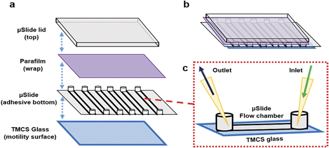
Figure 10. Microfluidic channel slide adapted to perform long-time IVMAs for HMM propelled actin filaments. (a) and (b) Schematic showing the addition of TMCS functionalized glass actin–myosin function and Parafilm for temporary sealing the entry points. (c) A section of single channel used as a flow chamber with entry points for assay inlet and outlet.
Download figure:
Standard image High-resolution imageWith the availability of the microfluidic-based flow cells, we were able to readily exchange the assay solution. We attempted to add fresh assay solution including GOC, ATP, etc after the motility was stopped but no recovery was observed. Then we suspected that the standard oxygen scavenger system based on, glucose oxidase (GOC) limits the motility up to 3–4 h due to the formation of gluconic acid with a pH drop in the assay solution that makes the myosin motors irreversibly non-functional. Initial results where we exchanged GOC for a pyranose oxidase based oxygen scavenger mixture (POC) gave similar motility quality (fraction of motile filaments, velocity) as GOC. However, whereas the longevity was extended, only a low fraction of the filaments moved after 4 h. (figures S.2(a)–(c)).
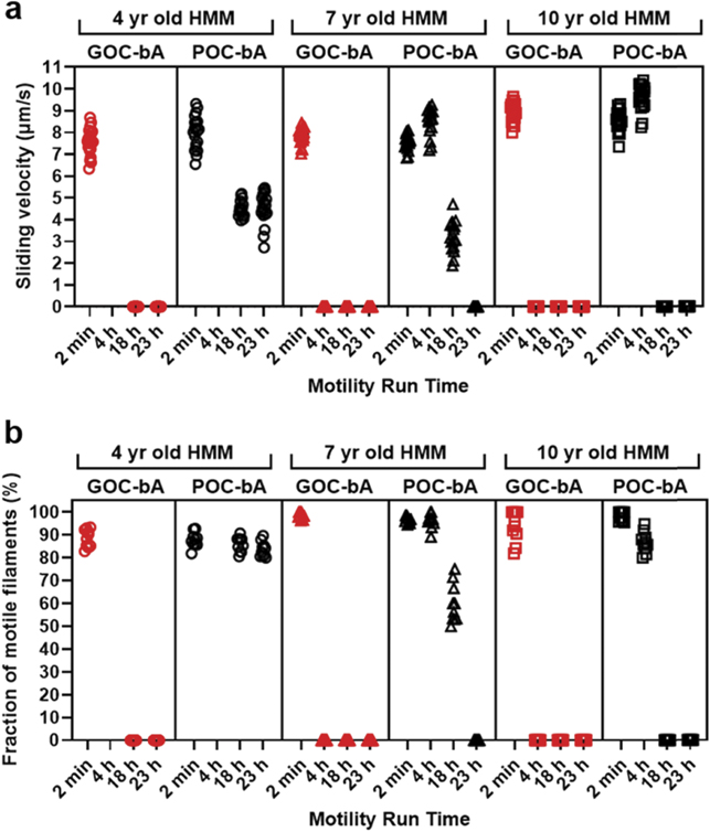
One possible basis for the decline in motility with time, despite exchange to POC based oxygen scavenger, could be HMM denaturation, e.g. due to prolonged surface interactions of the myosin motor domains. In support of this idea, we found that addition of blocking-actin to the POC-based assay solution provided additional benefits. Thus, with this addition we observed moderate to high sliding velocities and a high fraction of motile actin filaments for up to 23 h (figures 11(a) and (b), figure S.2(d)–(f)). The presence of blocking actin, which is expected to quite extensively cover the surface with non-fluorescent actin filaments [26] would bind also functional motors and thereby limit the time that the motor domains interact with the underlying surface. This, in turn, would limit the tendency for surface-mediated unfolding. However, even after exchange to POC and addition of blocking actin there was variability between different HMM preparations. Interestingly, the best longevity was seen for the least aged HMM preparation (figure 11).
Figure 11. Actin–myosin motility for three different HMM batches used in microfluidic based channel slide (cf figure 10). (a) Sliding velocity observed for assays with GOC or POC in the presence of blocking actin (bA) recorded at 2 min, 4 h, 18 h, and 23 h (temperature, 28 °C–29 °C). (b) The fraction of motile filaments observed for assays with GOC or POC in the presence of blocking actin recorded at 2 min, 4 h, 18 h, and 23 h (temperature, 28 °C–29 °C). In (a), 20 filaments were analysed for each time point. In (b), 10 different flow cell regions of interest were analysed for each time point. Note in (a) and (b), that for both 7 year and 10 year old HMM with GOC-bA, the sliding velocity and fraction of motile filaments was zero, 4 h after onset of the assay. Note further that for POC-bA, longevity was increased to >23 h for 4 years old HMM, >18 h for 7 years old HMM >4 h for 10 years old HMM.
Download figure:
Standard image High-resolution image
2.5. Long-term storage of proteins
In addition to increased longevity of the actual motility assay for large scale research and applications, it is also of interest to be able to store the protein components for a prolonged period for both ethical reasons, i.e. to limit the use of patient samples and experimental animals, and in order to reduce costs. Prolonged storage has been described to some extent before e.g. for actin filaments [34] and also myosin for motor fragments (HMM) being stored for years at −80 °C. Also, IVMA flow cells could be preserved for at least 1.5 months at −20 °C with all motility assay components present in the flow cell [35]. However, exact quantitative information has not been given for the HMM storage capability. We therefore investigated HMM preparations of different age stored in our −80 °C freezer. The results are described in table S.3, where currently observed velocity and fraction of motile filaments is compared with velocity and fraction of motile filaments observed early after the HMM preparation. These data suggest that storage at −80 °C is possible for more than 10 years without appreciable deterioration in function. However, our data in figure 11, indicate that prolonged storage may have negative impact on longevity during operation. This possibility, however, needs to be corroborated by additional experiments.
3. Conclusions
In conclusion, we found critical parameters that play vital roles in the prolongation and optimization of the function of actin myosin motility of great benefit for nanotechnological applications (particularly biocomputation) and large scale research. Our study emphasizes that it is of utmost importance to verify the biocompatibility, not only of surface substrates but also of any other material that is used to produce the microfluidic cells that hold the nanostructured chip with molecular motor function. The critical importance of this point was demonstrated by the dramatic effect of exchanging flow cell spacers despite their limited contact with the assay solution. Related to achievement of the desired surface chemistry for optimal motor function, one needs to consider adequate pre-treatments in the form of etching duration and type (isotropic) as well as suitably tuned silanization times. Limited air exposure of the proteins is critical at all stages of the assay. Means to achieve this requires extensive degassing of solutions, use of effective oxygen scavengers (POC instead of GOC) and sealing of the flow cell or use of reversibly sealable microfluidics chambers, as demonstrated here. The latter chambers, used for testing the POC system in the present paper, would be of interest to adapt to experiments with nanodevices, because it would allow exchange of components with limited lifetime such as dithiothreitol (DTT) if motility run-times longer than ∼ 1 day are desirable. Finally, our results also support the use of inert chamber systems as previously demonstrated to be effective to prolong the run-time of kinesin-microtubule motility assays [20]. Another important finding of this study, not at least for the sustainability of motor-filament based applications, is that prolonged storage of proteins for 10 years or more is possible at −80 °C. The storage capability can, however, vary between protein preparations (unpublished observations) and it is possible that prolonged storage is generally associated with reduced longevity of operation. The results and insights presented here will be important for the future developments of nanodevices using actin myosin motor complex, not the least in the biocomputation field [3] where prolonged motor-filament function is critical in solving large problems.
4. Materials and methods
4.1. Materials
All chemicals used in this study were of analytical grade and purchased from Sigma Aldrich except for Rhodamine Phalloidin and Alexa-647 ATP purchased from Thermo Fisher Scientific (Cat. No.: R415 and A22362). Double-sided adhesive thin-tape and standard double-sided adhesive thick-tape were purchased from 3M (3M-467MP and 3M-Scotch dispensered roll). Parafilm-M was purchased from Sigma Aldrich (Cat. No.: P7793). Microscope immersion oil, type-F was purchased from Nikon Instruments (Cat. No.: MXA22192), silicone vacuum grease from Beckman (Prod. No.: 335148), 1 ml syringes and 0.4 × 20 mm needles from B. Braun (Omnifix-F Solo and Sterican). Microfluidic multi-channel slides with hydrophobic polymer bottom (µ-Slide VI 0.4) and adhesive bottom (sticky-Slide VI 0.4) were purchased from Ibidi (Cat. No. 80606 and Cat. No. 80608).
4.2. Ethical statement
For muscle proteins, rabbits were sacrificed following the standard procedure and guidelines provided by the Regional Ethical Committee for Animal Experiments in Linköping, Sweden (reference number: 73-14).
4.3. Protein isolation and purification
Myosin was isolated and purified from rabbit fast skeletal muscle [36] and heavy meromyosin (HMM) was prepared by limited proteolysis using Nα-Tosyl-L-lysine chloromethyl ketone hydrochloride (TLCK) treated chymotrypsin [37, 38]. Actin was isolated and purified from rabbit back muscle as described earlier [37, 39]. Concentration and purity of the proteins were evaluated using absorbance spectrophotometry and sodium dodecyl sulphate polyacrylamide gel electrophoresis (SDS-PAGE).
4.4. Buffer for motility assay
All buffers and solutions were prepared with a low-ionic strength solution (LISS) as a major component. LISS solution was composed of 10 mM 3-(N-morpholino)propanesulfonic acid (MOPS), 1 mM magnesium chloride (MgCl2) and 0.1 mM potassium ethylene glycol-bis(β-aminoethyl ether)-N, N, N', N'-tetraacetic acid (K2EGTA), with final ionic strength of 15 mM and pH of 7.4. Wash buffer was prepared using LISS with addition of 50 mM KCl and 1 mM DTT. Assay buffer of ionic strength 60 mM was prepared using LISS with addition to the LISS solution of 10 mM DTT, 45 mM KCl, 2.5 mM creatine phosphate (CP), 0.2 mg ml−1 creatine phosphokinase (CPK), 1 mM magnesium adenosine triphosphate (MgATP) and, finally, an oxygen scavenger mixture (GOC): 3 mg ml−1 glucose, 0.1 mg ml−1 glucose oxidase, 0.02 mg ml−1 catalase. In some experiments, as specified above, glucose oxidase was replaced with 7.2 unit/ml of pyranose oxidase.
4.5. Flow cell assembly
In a standard flow cell, a glass coverslip (Menzel-Gläser, No. 0; 24 × 60 mm2), initially Piranha cleaned, and functionalized with trimethylchlorosilane (TMCS) was used as bottom surface [28] (Caution: Piranha solution is highly corrosive and acidic and may also cause explosion upon contact with organic substances). Above it, two strips of double-sided adhesive thick tape were placed as spacers with an approximate gap of 15–20 mm. This was followed by top surface, which was a square coverslip (18 × 18 mm2) to complete the flow cell assembly. In flow-cells with nanodevices untreated glass coverslips (No. 0; 24 × 60 mm2) were used for the flow cell floor. Above it, either two strips of double-sided adhesive thin tape were used as a spacer or two Parafilm strips stretched to the tension limit. The gap between the two spacers was approximately 8–10 mm. The nanofabricated chip (8 × 10 mm2) was placed on top. In the case when Parafilm was used as spacer, the flow cell was heated to melt the Parafilm and thereby compress the thickness to around 0.04 mm.
4.6. Microfluidic multi-channel flow cell assembly
In a microfluidic multi-channel flow cell (figure 10), a glass coverslip (No. 0; 24 × 60 mm2), functionalized with TMCS, was used as floor. Above it, an adhesive multi-channel microfluidic slide was placed followed by tapping around the sticky regions to confirm proper attachment between the two surfaces. All entry points in the multi-channel slide were sealed after solution exchange using a Parafilm wrap to minimize air exposure. On top, a glass-slide, lid was placed to tightly close the assembly.
4.7. Degassing and sealing
Degassing was performed for LISS as being the main constituent of all solutions. The LISS buffer was transferred to a conical flask with side outlet connected to the air suction line. The flask was covered from the top using a rubber stopper to create low air pressure during suction. For approximate solution volume of 20 ml, degassing was done for at least 40 min. After degassing, assay and wash buffer solutions were stored in small plastic tubes (kept on ice) with blow of N2-gas while opening or closing to avoid air exposure. Once the buffers were prepared, the tubes were wrapped using Parafilm around the opening. Assay buffer in particular, was carefully transferred further to a 1 ml syringe fitted with a hypodermic needle. This assembly was then covered with aluminium foil and Parafilm wrap respectively. Sealing of the flow cell was applied after all IVMA incubation steps were performed. For this purpose we used silicon vacuum grease that was applied with the help of a tip/needle, filling both open ends and also covering top edge of the flow cell.
4.8. In vitro motility assay
IVMAs [26, 40], were performed in flow cells assembled as described above. The flow cells were incubated in step-wise manner: starting with heavy meromyosin (HMM in wash buffer; 120 μg ml−1) for 5 min, followed by bovine serum albumin (BSA in wash buffer; 1 mg ml−1) for 2 min, 1 volume rinsing with wash buffer, then incubation with blocking actin (non-fluorescent actin filaments in wash buffer; 1 μM) for 2 min, followed by magnesium adenosine triphosphate (MgATP in wash buffer; 1 mM) for 2 min, 2 volumes rinsing with wash buffer, further incubation with rhodamine-phalloidin labelled actin filaments (in wash buffer; 10–15 nM), followed by 1 volume rinsing with wash buffer and finally, assay buffer was added and kept for 2 min prior to observations on the microscope.
4.9. Imaging and filament tracking
An inverted fluorescence microscope (Axio Observer.D1 from Zeiss) was used for the observation along with a 63× (Apochromat, NA = 1.4, WD = 0.19 mm) and 40× (NA = 1.3, WD = 0.21 mm) oil immersion objective. For excitation of rhodamine fluorescence, a short-arc mercury lamp (103 W/2, from OSRAM) was used with optimum filter set (Cy3). Image acquisition was performed using an electron multiplying charge-coupled device (EMCCD) camera (C9100-12PHX1, from Hamamatsu Photonics). Image sequences were taken at pixel size of 0.24 × 0.24 μm2 for a 63× objective, where fluorescently labelled actin filaments were recorded at a frame rate of 4.95 frames/second. All observations were performed within the temperature range of 22 °C–29 °C (see legends for details) while keeping it maintained within ±1 °C during each given experiment, using a ring shaped temperature controller (Temp controller 2000-2, from Pecon) fixable on top of the objective. For filament tracking, sliding velocities were calculated as explained earlier using the software Matlab [16, 41]. The fraction of motile filaments calculation and maximum projection of stacks images were produced using the software ImageJ.
4.10. Nanofabrication
The fabrication of the computational networks was done on a single side polished 150 mm Si (100) wafer. A 70 nm thick SiO2 layer on the Si-substrate was grown by dry thermal oxidation. The layer growing was carried out under oxygen atmosphere with 3% HCl. After an O2 plasma cleaning and surface activation steps for 30 s, a resist layer (ALLRESIST AR-P 6200:10) was spin-coated onto the SiO2, to a thickness around 400 nm and soft baked at 180 °C for 2 min. The network was patterned by EBL (Vistec SB254) with a dose of around 100 μC cm−2. The AR-P 6200:10 was developed in 600594 developer for 60 s, rinsed with IPA and flushed in a conductance-controlled DI-water bath. The wafer was then spun dry and separated into 1 cm2 chips. Finally, in order to remove organic resist residuals from the e-beam lithography exposed areas and modify the surface chemical properties etching was performed. The anisotropic etching was performed with a Nano-etcher (Moorfield Nanoetch Tool) using O2 at a flow rate of 20 sccm and 5 W RF power. However, in our optimized protocol, isotropic etching was performed with a plasma etcher (New PlasmaPreen Asher) utilizing a Faraday cage, using O2 at 10 mbar partial pressure. The process lasts 45 s unless otherwise stated. Etching rate tests suggest that the lateral etching rate for the setup is close to 0.4 nm s−1. Therefore, the etching would contribute at most 36 nm extra nanochannel width. In the centre of the pass junction (figure 6), where most severe computational errors could occur, the width normally ranged from 400 to 800 nm. Therefore the broadening effect caused by isotropic etching for 45 s plays a negligible role for the junction error rate.
4.11. Vapour silanization
To make the surface suitable for HMM driven actin filament motility, we performed silanization with trimethylchlorosilane (TMCS). In detail, the samples were O2 plasma etched (Plasma Preen II-862, Plasmatic Systems, Inc., North Brunswick, NJ) at 5 mbar for 45 s to remove resist residues and remove adsorbed water molecules. The etching was performed within a Faraday cage to achieve isotropic etching so the sidewalls in the nanostructures were etched as well. The samples were then immersed in DI-water for 5 min to generate as many as possible hydroxyl groups on the surface for later silanization. The silanization was then done in a controlled chemical-vapour deposition (CVD) system following the method as described [9].
4.12. Contact angle measurements
To determine the hydrophobicity of the surface after various treatments, we performed static contact angle measurements at 22 °C using a Theta Lite Optical Tensiometer. A sessile drop of ultrapure water was dropped onto the surface using a manual syringe dispenser. The droplet was imaged using a FireWire camera with telecentric optics and monochromatic LED-based background lighting. We used the OneAttension software (Biolin Scientific, Västra Frölunda, Sweden) to perform computer analysis of the drop profile and extract the contact angle data from the Young equation.
4.13. Scanning electron microscopy
The topography of the devices was imaged by scanning electron microscopy (Hitachi SU8010). To improve the conductivity of the surface, 5 nm of Pt:Pd (80:20) was deposited on top of the device via metal sputtering (Q150T Plus—Turbomolecular pumped coater, Quorum).
Acknowledgments
We would like to thank Till Korten, Falco van Delft and Sven Tågerud for providing important suggestions and insights. This project has received funding from the European Union's Horizon 2020 research and innovation programme under Contract 732482 (Bio4comp), NanoLund, The Swedish Research Council (Grant Nos. 2015-05290 and 2019-03456), the Volkswagen Foundation (Project 93 440), and The Faculty of Health and Life Sciences at The Linnaeus University, Sweden.
Data availability statement
The data that support the findings of this study are available upon reasonable request from the authors.