


All-dielectric metasurfaces have been attracting much attention. Low optical losses and a huge variety of optical modes provide unique possibilities for light manipulation at the nanoscale. Recent studies showed that the magneto-optical effects in such metasurfaces are enormously enhanced. Moreover, it is possible to observe novel magneto-optical effects that are absent in smooth films. Excitation of particular photonic resonances makes it possible to design the magneto-optical interaction by the metasurface design. This opens up broad opportunities for magneto-photonic metasurface applications, including optomagnetism, light modulation, sensing, magnetometry, etc.
I. INTRODUCTION
The concept of artificial metamaterials and metasurfaces appeared in the early 2000s.1,2 It was shown that an artificial material made of subwavelength elements, so-called “meta-atoms,” possessing resonant properties, could have outstanding characteristics. The size of the elements in the visible range makes it nearly unrealistic to implement the concept of a bulk metamaterial working at submicrometer wavelengths. At the same time, recent studies showed that a thin, subwavelength layer of meta-atoms, forming a metasurface, can efficiently control the properties of the light passing through it,3 such as polarization,4,5 intensity,6 phase,4,5 etc.7–9 Such an ability is of prime importance for the miniaturization of many optical devices.
For a decade, several types of metasurfaces with metallic meta-atoms, such as split-ring resonators1,2 and plasmonic nanoantennas,10,11 were studied. Such meta-atoms usually have prominent resonant properties; however, the presence of metallic layers brings absorption to the system. Usually, the resonant properties of the plasmonic-based metasurface have small Q-factors. Thermal heating of metals also puts limitations on the power of the light that can be controlled by the metasurface.
Nowadays, much attention is attracted by the low-loss all-dielectric metasurfaces.12,13 They are formed using high-refractive-index dielectric elements in a low-refractive-index surrounding.14 Such metasurfaces are nearly free of optical absorption while their spectral response can have a resonant form due to the optical modes excited in such metasurfaces. Mie- or Fabry–Pérot-type resonances can be excited in individual dielectric elements giving rise to a wide variety of polarizations, dispersions, and Q-factors of such localized optical modes15 caused by a combination of high refractive index, size, and shape effects.13 The periodical arrangement of such elements makes the interaction between them important16 and enriches the structure with the lattice17–19 or guided resonances.20 All-dielectric metasurfaces provide a possibility of linear and nonlinear optical phenomena observation at nanoscale12,15,21 and are promising for light manipulation,20 spectroscopy, sensing,22–24 information processing,25,26 etc.
The design of the meta-atoms forming a metasurface makes it possible to tune not only the optical properties of the structure but its magneto-optical response as well. This gives an exciting possibility to “construct” the desired magneto-optical effects by the metasurface design. Recent studies reviewed in the present Perspective showed that the magneto-optical effects, such as transverse, longitudinal, polar Kerr, and Faraday effects, could be enormously enhanced in the magnetic metasurface at a resonant wavelength determined by metasurface parameters rather than a material composition. This makes it possible to combine the enhanced magneto-optical effects with a high intensity of the transmitted or reflected signal. Different spectral positions, dispersion, and quality-factor of the magneto-optical resonances could be achieved. It is important that magneto-optical metasurfaces could exhibit magneto-optical properties that could not be found in the natural magneto-optical materials, one of which is the gyromagnetic response at optical frequencies.
As the light localization in such structures goes down to tens of nanometers scale, the surface effects produced by the crystalline structure become extremely important. Recent studies in Bi-substituted iron garnets have shown a large increase in the magneto-optic Faraday response within a few nanometers of the surface.27–30 This effect has been traced back to surface reconstruction in these materials. Measurements performed via scanning tunneling electron microscopy and circularly polarized x-ray photon absorption indicate that a reconfiguration in the surface-electron density of states plays a role in the observed enhancement in the Faraday response. This suggests that a controlled surface reconstruction in the atomic distribution through present-day nanofabrication technology may yield advanced magneto-photonic meta-surfaces leading to new developments in the telecommunications’ industry.
The review is organized as follows. First, we briefly review the main types of magneto-optical effects observed for different light and magnetization orientations. Then, we discuss magneto-optics of metasurfaces with Mie resonances. Those are the resonances attributed to individual nanoelements of the structure and determined predominantly by the nanoelement geometric sizes, shape, and material. We discuss how the properties of these resonances affect the interaction of light with magnetization of the metasurface. Then, we discuss metasurfaces with a periodic arrangement of nanoelements that support the excitation of guided modes. We discuss the peculiarities of the 1D and 2D nanoelement arrangements that give rise to the unusual magneto-optical response. Both Mie- and guided-resonance supporting metasurfaces could support bound states in the continuum (BICs), which is a non-radiating state co-existing with the continuum of radiating ones. We give a brief overview of the studies of the magneto-optical metasurfaces supporting such bound states in the continuum and arising from their ultrahigh Q-factors and high sensitivity to light parameters. After that, we discuss the surface effects observed in the ultrathin magneto-optical materials and summarize the preliminary studies in the Faraday response and surface reconstruction. Finally, we give an overview of how one may benefit from using the magneto-optical all-dielectric metasurfaces in various practical devices.
II. MAGNETO-OPTICAL EFFECTS IN SMOOTH FILMS
Magnetization of the material affects the properties of the light propagating through this material. The magneto-optical interaction can be described using ordinary constitutive equations by introducing magnetization-dependent terms in the permittivity tensor31 ,
where is a gyration vector parallel to material static magnetization M and has a value (also known as gyration coefficient) that depends on material properties. Usually, the gyration coefficient is much smaller than permittivity so the magneto-optical interaction can be analyzed using a perturbation theory. Magneto-optical changes of the permeability tensor at optical frequencies are negligible. Thus, one may say that all of the natural materials exhibit gyroelectric response rather than gyromagnetic or bigyrotropic response.
The impact of magnetization on light properties depends on the mutual orientation of the light wavevector k and the magnetization direction M. Usually, three basic orientations of magnetization in the films are considered (see schemes in Fig. 1):31
Faraday (polar) configuration with magnetization perpendicular to the magnetic film. Light incidence on the magnetic material has a nonzero (k,M) scalar product. In this case, eigen modes have right and left circular polarization with different refractive indices , where corresponds to parallel to the k component. The difference of the real parts of causes the magneto-optical rotation of light linear polarization transmitted (Faraday effect) and reflected (polar Kerr effect) from the magnetic material. The difference in the imaginary parts of leads to the polarization- and magnetization-dependent absorption and corresponds to the magnetic circular dichroism effect.
Longitudinal (Voight) configuration with the magnetization lying in the plane of incidence and in the plane of the magnetic film. At the oblique incidence, the situation is similar to the Faraday configuration discussed above. As the (k,M) scalar product is non-zero, polarization rotation is also observed for the reflected and the transmitted light (longitudinal Kerr effect). This effect is small for the small angles and completely vanishes at normal incidence where .
Transverse (Voight) configuration with magnetization lying perpendicular to the plane of incidence and in the plane of the magnetic film. The changes in the constitutive equations [see Eq. (1a)] affect the boundary conditions and this result in variation of the reflectance and transmittance of the magnetic film (transverse Kerr effect). This effect is observed only for p-polarized light (due to the gyroelectric type of the response), vanishes at normal incidence, and is extremely weak (∼0.01%) for transparent materials.
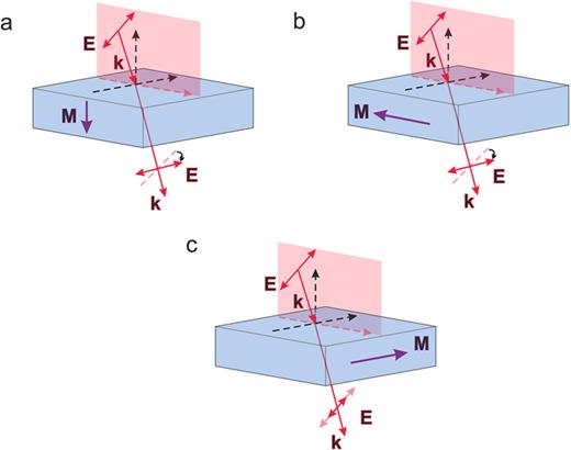
Configurations of three basic magneto-optical interactions in smooth films: (a) Faraday configuration, (b) longitudinal configuration, and (c) transverse configuration in transmittance.
Configurations of three basic magneto-optical interactions in smooth films: (a) Faraday configuration, (b) longitudinal configuration, and (c) transverse configuration in transmittance.
In both longitudinal and transverse configurations quadratic on the gyration coefficient, the so-called Voight effect appears. Quadratic on the gyration magneto-optical linear birefringence leads to the transformation of the polarization of light. However, this effect is usually much smaller than the linear on gyration effects described above.
The near-field light properties in the metasurfaces significantly differ from that of the incident light. This cause the transformation of the magneto-optical effects in the metasurfaces compared to the magneto-optics of the smooth films.
III. MAGNETO-OPTICAL METASURFACES WITH MIE RESONANCES
A. Mie modes
In 1908, Gustaf Mie described variation in colors of gold nanoparticles in terms of their size distribution.32 Such difference in the scattering properties arises due to the presence of optical resonances whose position is determined by the nanoparticle size and permittivity. Optical resonances of the same nature do exist in both metallic and dielectric nanoparticles.33 While metallic particles initially described by Mie possess high optical losses, their dielectric counterparts lack this feature.
Mie resonances can be described by solving the scattering problem of light with wavelength on a single particle with arbitrary radius R and refractive index n. The total scattering and extinction cross section can be represented as a series of spherical multipolar terms,
where and are Mie coefficients of mth-order electric and magnetic multipolar modes and λ is the free space wavelength. Thus, the absorption and scattering cross sections possess the resonances that correspond to the maxima of and coefficients and depend on the ratio of the wavelength and sphere diameter [Fig. 2(a), see also Ref. 33].
Each electric and magnetic order of the resonances possesses different distribution of electromagnetic fields inside the sphere. The resonant nature of the phenomena is accompanied by an enhanced electromagnetic field not only inside the sphere but also in its vicinity. The lowest Mie resonances are represented by magnetic dipole (MD) and electric dipole (ED) modes. The electric (magnetic) field of the corresponding ED (MD) mode is oriented in a certain direction inside a nanoparticle while the magnetic (electric) field is twisted around it [Fig. 2(b), see also Ref. 35]. Such peculiar field distribution as well as its resonant amplification under excitation of Mie resonances give rise to significant modification and enhancement of magneto-optical interactions in Mie-supporting structures.

Mie resonances in dielectric nanoparticles. (a) Scattering and absorption cross section of a Si spherical nanoparticle in free space. Calculated using a Mie calculator34 with parameters from Ref. 33. (b) Electric and magnetic fields of the electric and magnetic dipole Mie modes excited in a nanocylinder by a linearly polarized incident light. Reproduced with permission from Kruk and Kivshar, ACS Photonics 4, 2638 (2017).35 Copyright 2017 American Chemical Society. (c) Dependence of Mie resonance positions in dielectric nanospheres on their refractive indices. Reproduced from Kuznetsov et al., Sci. Rep. 2, 492 (2012).36 Copyright 2012 Author(s), licensed under a Creative Commons Attribution (CC BY) license.
Mie resonances in dielectric nanoparticles. (a) Scattering and absorption cross section of a Si spherical nanoparticle in free space. Calculated using a Mie calculator34 with parameters from Ref. 33. (b) Electric and magnetic fields of the electric and magnetic dipole Mie modes excited in a nanocylinder by a linearly polarized incident light. Reproduced with permission from Kruk and Kivshar, ACS Photonics 4, 2638 (2017).35 Copyright 2017 American Chemical Society. (c) Dependence of Mie resonance positions in dielectric nanospheres on their refractive indices. Reproduced from Kuznetsov et al., Sci. Rep. 2, 492 (2012).36 Copyright 2012 Author(s), licensed under a Creative Commons Attribution (CC BY) license.
In order to observe the resonances in the subwavelength particles at optical frequencies, one needs to use high-index materials. At optical frequencies, all-dielectric nanoparticles are typically formed from low-loss, high-index semiconductors, such as Ge, GaAs, GaP, and Si (for details on materials for all-dielectric nanophotonics, see the review13). The spectral position of the Mie resonance significantly depends on the nanoparticle size,37 refractive index [Fig. 2(c), see also Refs. 36 and 38–40], and periodic arrangement when they form a lattice.17–19,41 If a period of the structure is larger than the wavelength of the incident light, the lattice produces non-zero diffractive orders in transmission and reflection that can influence transmission and reflection spectra of the system typically measured in 0th order.42,43
B. Magneto-optics of Mie-supporting metasurfaces
One of the first studies on the magneto-optics of Mie nanoparticles was performed by a group under the supervision of Professor A. Garcia-Martin, who theoretically showed enhanced magneto-optical polarization conversion in core–shell nanoparticles.44 The core of hybrid particles was uniformly doped with a magneto-optical material with parameters similar to iron garnets. The spectrum of the nanoparticle in the infrared region comprises several Mie resonances including magnetic dipole (MD), electric dipole (ED), and magnetic quadrupole (MQ). The most significant magneto-optical polarization conversion enhancement up to five times was observed at the positions of MD and MQ resonances. This enhancement was found to be dependent on the electromagnetic field concentration inside the magnetooptical core. As a result, it can be controlled by proper selection of nanoparticles size and refractive index.
Magnetically tunable directionality of light scattering is feasible in spherical microresonators coated by a magneto-optical material in a THz regime.45 The authors of Ref. 45 proposed an approach for the control of backscattering by turning on/off an external magnetic field. Gyroelectric components of the permittivity tensor that are sensitive to the external magnetic field lead to the tunability of the Kerker condition and, therefore, the amount of radiation scattered forward/backward by the metasurface. The considered structures were found to be scalable to nanosize.
For various practical applications, spherical particles are not suitable and complicated in production. From this point of view, all-dielectric gratings that are composed of periodically ordered nanoparticles of different shapes are very convenient for on-chip implementation. In some cases, 1D grating formed by high refractive-index stripes could support Mie resonances too.38,46,47 It can be treated as a disk infinitely stretched in one of the directions with a consequent limitation on polarization that could excite a mode. The combination of nanogratings with magneto-optical materials in the form of heterostructures is shown to be suitable for magneto-optical effects’ enhancement, modulation, and modification. The two main strategies in device fabrication for Mie resonance-induced magneto-optics can be summarized as follows:
Formation of semiconductor-based arrays of nanoparticles (mainly disk shape) on/under a smooth layer or heterostructure of magneto-optical material.
Formation of arrays of magnetic all-dielectric nanoparticles on a substrate.
One of the most practically important ways of excitation of Mie modes in a magneto-optical metasurface is based on the utilization of two-dimensional arrays of Mie-mode supporting Si nanodisks combined with magnetic materials. The production process of such Si disk arrays is integrated into standard semiconductor technology. At the same time, using Si disks as Mie resonators, one gets a degree of freedom in the choice of the magnetic material surrounding the disk. Nowadays, such Si-based metasurfaces were implemented using various magnetic materials, such as ultrathin Ni films,51,52 ultrathin Pt/Co multilayers,49 and iron-garnets.50,53 This provided a huge diversity of magneto-optical effects observed in such Si-based magneto-optical metasurfaces.
Magneto-optical intensity effect observed for a transverse magnetization experienced 4 times increase48 under MD resonance excitation in Mie-supporting metasurface composed of a-Si:H nanodisks with 5-nm-thick Ni layer [Fig. 3(a)]. The effect was induced by an enhanced local electric field inside the Ni layer. Similar structures were also found to be efficient for the Faraday effect enhancement.51,52 Up to 6× and 11× fold enhancement of Faraday and Kerr rotation correspondingly was reported for the Mie-supporting Si nanodisk array on the SiO2/[Pt(0.7)/Co(0.6)]N/SiO2 multilayered heterostructure. Enhancement of the phenomenon similar to the magnetic circular dichroism was also demonstrated.49 Transmitted and reflected light intensities at resonant ED and MD modes significantly differ for left and right circularly polarized light [see scheme in Fig. 3(b)]. This difference changes under the variation of the magnetization direction giving rise to an intensity modulation of ∼3% [Fig. 3(b)]. The Co/Pt multilayer with perpendicular magnetic anisotropy was initially saturated, so the system was not undergoing an external magnetic field during magneto-optical experiments. Magneto-optical response of multilayered structures, such as Co/Pd or Co/Pt that is widely used for magnetization reversal,54–56 can also be enhanced with Mie nanophotonics.

Magneto-optics of Mie-supporting metasurfaces. (a) Spectra of the transmittance and the magneto-optical response (intensity modulation) in a-Si:H disk-based metasurface covered with 5-nm-thick Ni film (see the configuration in the inset). The resonant enhancement of the MO response is observed at MD mode excitation. Reproduced with permission from Barsukova et al., ACS Photonics 4, 2390 (2017).48 Copyright 2017 American Chemical Society. (b) The relative reflectance variation gR observed in the Si-based metasurface with Pt/Co multilayers under the light helicity change. Reproduced with permission from Abendroth et al., Adv. Opt. Mater. 8, 1 (2020).49 Copyright 2020 John Wiley and Sons. (c) TMOKE observed in s-polarized light due to the effective gyromagnetic response (left) and giant Kerr rotation observed at the small angle of incidence (right) in the Mie-supporting metasurface. Reproduced with permission from Xia et al., Laser Photonics Rev. ■, 2200067 (2022).50 Copyright 2022 John Wiley and Sons.
Magneto-optics of Mie-supporting metasurfaces. (a) Spectra of the transmittance and the magneto-optical response (intensity modulation) in a-Si:H disk-based metasurface covered with 5-nm-thick Ni film (see the configuration in the inset). The resonant enhancement of the MO response is observed at MD mode excitation. Reproduced with permission from Barsukova et al., ACS Photonics 4, 2390 (2017).48 Copyright 2017 American Chemical Society. (b) The relative reflectance variation gR observed in the Si-based metasurface with Pt/Co multilayers under the light helicity change. Reproduced with permission from Abendroth et al., Adv. Opt. Mater. 8, 1 (2020).49 Copyright 2020 John Wiley and Sons. (c) TMOKE observed in s-polarized light due to the effective gyromagnetic response (left) and giant Kerr rotation observed at the small angle of incidence (right) in the Mie-supporting metasurface. Reproduced with permission from Xia et al., Laser Photonics Rev. ■, 2200067 (2022).50 Copyright 2022 John Wiley and Sons.
The nanodisk shape of the particles makes it possible to tune MD and ED resonance positions simultaneously by varying the ratio of the disk height and radius. Christofi et al.57 theoretically examined the periodically structured two-dimensional array of BIG-based nanodisks embedded into silica media possessing ED and MD resonances near telecom wavelength. The Faraday effect is amplified at both resonances. Moreover, when ED and MD resonances overlap, enhanced Faraday rotation is accompanied by increased optical transmission. Such overlap boosts the magneto-optical figure of merit (determined as57 , where T and are transmission and polarization rotation, respectively) to exceed 7.35°.
Peculiarities of the near-field distributions of the Mie modes give birth to the unusual magneto-optical effects. Typically, in optical and infrared frequency ranges, the magneto-optical response is produced by the gyroelectric properties of the material, i.e., its magnetization impacts the permittivity tensor while the permeability remains close to 1. “Meta-atoms” could drastically change this situation and provide a gyromagnetic response of the metasurface due to displacement currents, first observed for plasmonic nanoelements.58 A Si-disk-based metasurface on a surface of a cerium-doped yttrium iron garnet (CeYIG) thin film also provides such a possibility giving rise to a giant TMOKE = R(+M) − R(−M)/(R(+M) + R(−M)) up to 6.4% effect observed for s-polarized light50 [Fig. 3(c)]. Moreover, the displacement currents excited in the metasurface give rise to the giant LMOKE effect in transmission. Experimentally obtained polarization rotation in a metasurface reaches 1°, which is two orders of magnitude higher than in a smooth film at near-zero angles of incidence [Fig. 3(c)].
IV. MAGNETO-OPTICAL METASURFACES WITH GUIDED-MODE RESONANCE
A. Guided mode resonant gratings
Guided mode resonant gratings are dielectric periodic lateral structures that support the excitation of guided modes by evanescent diffraction orders. Such gratings are widely used as sensors, signal processing devices, optical security labels, spectrometers, wave plates, active tunable filters, mirrors for lasers, and in many other practical applications (for a detailed review on applications of guided-mode gratings, see Ref. 59). A key feature of such gratings is their tunability, as the optical properties, such as polarization, dispersion, and Q-factor of the resonances, can be efficiently controlled by a grating design.37,59 While for excitation of Mie resonances one has to choose high-index semiconductor materials,13 guided-mode resonances can be excited in a wider range of materials, having higher refractive index than that of the surrounding medium, including oxides TiO2, Ta2O5, and others.59
Generally speaking, a non-magnetic waveguide supports families of modes of TM and TE types, with different mode numbers m = 0, 1, 2, 3, … that are responsible for the number of electromagnetic field nodes inside a waveguide core. The properties of the guided modes are sensitive to the external magnetic field applied to the core and depend on the orientation of the external magnetic field.
For a transverse magnetization of the waveguide core, corresponding to the external magnetic field applied in-plane perpendicular to the mode propagation direction, the non-reciprocal variation of the dispersion of the TM-modes is observed, while the properties of the TE-modes remain unchanged. Magneto-optical variation of the TM-mode propagation constant is odd on magnetization and the propagation direction, (see Ref. 60 for details).
Longitudinal (in-plane, parallel to the propagation direction) and Faraday (or polar, out-of-plane) magnetization of a waveguide core result in eigen polarization changes of both modes. In a nonmagnetic case, guided modes obtained as exact analytical solutions to Maxwell's equations have linear eigen polarization (for example, the TM-mode is characterized by the components of the electromagnetic field). Under the application of the magnetic field in the Faraday or longitudinal configuration, the eigenmodes have all six non-zero components of the electromagnetic field. For example, the TM mode preserves its frequency as in the non-magnetic case, but in addition to the non-magnetic electromagnetic field components acquire small linear in magnetization orthogonal ) components.61 It can be treated as a quasi-TM mode. For thick waveguides with close frequencies of TM and TE modes, this phenomenon is responsible for the energy swap between the modes and Faraday rotation of linearly polarized light passing along a slab waveguide.62 However, in subwavelength-thick waveguide gratings, the frequencies of TM and TE modes differ significantly giving rise to other types of magneto-optical effects, as it is discussed further, see Secs. IV B and IV C.
B. 1D magneto-optical metasurfaces
The enhancement of magneto-optical effects employing 1D magneto-photonic crystals, arranged as multilayer systems, has been intensively studied at the beginning of this century.63,64 In such systems, Bragg interferences of light propagating perpendicularly to the multilayer plane lead to the formation of photonic bandgaps in the light spectrum. When the magnetic layer is placed as defect at the center of the cavity, MO Faraday effect is enhanced at the center wavelength, through multiple round-trip in the MO layer, leveraging the non-reciprocity of MO effects. In the case of a distributed cavity with alternating magnetic and non-magnetic layers, light matter interaction is enhanced at the edge of the bandgap through the flattening of bands that induces a decrease in the waves’ group velocity. In this case, the enhancement of the Faraday effect takes place on both sides of the bandgap.65 In both situations, the MO coupling efficiency between perpendicularly polarized waves is optimal because of the full degeneracy of these waves that propagate with exactly the same wave vector. This is the phase-matching condition that is perfectly fulfilled.
The enhancement of magneto-optical effects through all-dielectric metasurfaces in based on the resonant coupling of outside plane-waves to specific modes of the surface that should behave as a planar waveguide. Such waveguide is classically made of a MO high index layer coated on a low index-specific substrate. The coupling can be obtained through a 1D sub-wavelength grating leading to guided mode resonance, when the coupling equation is satisfied,
is the wavevector of the guided mode, is a tangential component of the incident light, is the wavelength, is the incidence angle, is a reciprocal lattice constant, P is the period of the grating, and m is the integer. Incoming light is coupled to the waveguide thanks to the 1D grating, propagates in the guide, and is finally coupled outside through the same grating. Compared to a single path through the MO layer, the propagation distance of the light in the MO material is increased. MO polarization effects like Faraday or longitudinal/polar Kerr effects being proportional to the travel distance in the MO material, such effects can be enhanced through guided mode resonance. But, contrary to multilayer devices, the phase-matching condition is not easily satisfied. Indeed, in a planar waveguide, TE and TM modes possess different propagation constants. To obtain an efficient mode conversion, it is, thus, required to find a way to match these constants. In magneto-plasmonic devices, made of a gold grating on the top of a MO planar waveguide, as TM and TE modes are not belonging to the same guided phenomenon, their dispersion relations possess different behaviors as a function of the grating period. It is, thus, not so difficult to find a period for which the wavevectors matching is realized.66
On the contrary, in all-dielectric planar waveguides, the dispersion relation of TE and TM modes as a function of the grating period does not cross, and the phase-matching condition cannot be fulfilled. It is, thus, required to modify the device and use, for instance, a photonic crystal membrane that plays both the role of the waveguide and the 1D grating [Fig. 4(a)]. In that situation, by a proper adjustment of the geometrical parameters of the membrane, a TE/TM phase-matching situation can be obtained, leading to simultaneous excitation of both polarizations at the same incident angle. In that situation, Faraday effect enhancement at the resonance can theoretically be hundred times the off-resonance value.67 In the same manner, longitudinal and polar Kerr effects can also be largely enhanced. Because the processing of classical MO material like YIG is still challenging on photonic platforms, such photonic crystals membrane has been realized through the impregnation of a silicone nitrite 1D grating by a sol-gel solution doped with magnetic nanoparticles. Such nanocomposite material can easily be coated and processed on several photonic devices. Finally, the enhancement of the Faraday effect has been experimentally demonstrated by Royer et al. in an all-dielectric magnetic device employing such membrane.68 Compared to the theoretical situation, experimental enhancement is less (fourfold only) because of deviations of technological parameters leading not to a perfect phase-matched situation [Fig. 4(a)]. This device was also employed to experimentally demonstrate the longitudinal Kerr effect enhancement. Such effect has also been enhanced in a device made of a photoresist grating on top of a MO nanocomposite film that behaves as a planar waveguide [Fig. 4(b)]. The phase matching was also not fully satisfied, but the quality of the resonance leads to large enhancements for several incidence, when compared to the reference layer.69

Polarization rotation in the 1D magneto-optical metasurface. (a) Experimental demonstration of both Faraday and longitudinal Kerr effects through a Si3N4 membrane impregnated with a MO nanocomposite. Reproduced with permission from Royer et al., ACS Omega 5, 2886 (2020).68 Copyright 2020 American Chemical Society, licensed under an ACS AuthorChoice License. (b) Longitudinal Kerr effect enhancement with a photoresist (PR) grating on top of a MO waveguide incidence angle of 1°, 3°, and 5°. Reproduced with permission from Bsawmaii et al., Opt. Express 28, 8436 (2020).69 Copyright 2020 Optical Society of America, licensed under OSA Open Access Publishing Agreement.
Polarization rotation in the 1D magneto-optical metasurface. (a) Experimental demonstration of both Faraday and longitudinal Kerr effects through a Si3N4 membrane impregnated with a MO nanocomposite. Reproduced with permission from Royer et al., ACS Omega 5, 2886 (2020).68 Copyright 2020 American Chemical Society, licensed under an ACS AuthorChoice License. (b) Longitudinal Kerr effect enhancement with a photoresist (PR) grating on top of a MO waveguide incidence angle of 1°, 3°, and 5°. Reproduced with permission from Bsawmaii et al., Opt. Express 28, 8436 (2020).69 Copyright 2020 Optical Society of America, licensed under OSA Open Access Publishing Agreement.
Apart from the MO polarization rotation effect, 1D all-dielectric metasurfaces can also induce large modification of intensity effects like Transverse Magneto-Optical Kerr effect (TMOKE). This is the magneto-induced variation of TM light transmitted through (or reflected from) the device when it is submitted to a magnetic field transverse to the incidence plane. In this situation, the propagation wavevector of the TM modes has a non-reciprocal dependence on the magnetic field direction. The variation of the magnetic field induces a spectral shift of the resonance, leading to the TMOKE effect that measures the relative transmittance (reflectance) difference [Fig. 5(a)]. Such effect has been intensively studied in 1D magneto-plasmonic devices that support plasmonic TM modes.70 But the quality factor of the resonance obtained in plasmonic devices is low (Q ∼ 10) because of the high absorption of metallic materials.

Experimental demonstration of the enhancement of TMOKE through 1D guided mode resonant devices. (a) Schematic of the device (P = 500 nm and W = 200 nm); comparison between the impact of real and imaginary parts of guided-mode propagation magneto-induced variation on the TMOKE resonance; TMOKE effect. Reproduced with permission from Voronov et al., Opt. Express 28, 17988 (2020).72 Copyright 2020 Optical Society of America, licensed under OSA Open Access Publishing Agreement. (b) Schematic of the device, TMOKE measured in reflection at 2°, 4°, and 5.5°, numerical RCWA simulation of TMOKE. Reproduced with permission from Bsawmaii et al., Opt. Mater. Express 12, 513 (2022).73 Copyright 2020 Optical Society of America, licensed under OSA Open Access Publishing Agreement.
Experimental demonstration of the enhancement of TMOKE through 1D guided mode resonant devices. (a) Schematic of the device (P = 500 nm and W = 200 nm); comparison between the impact of real and imaginary parts of guided-mode propagation magneto-induced variation on the TMOKE resonance; TMOKE effect. Reproduced with permission from Voronov et al., Opt. Express 28, 17988 (2020).72 Copyright 2020 Optical Society of America, licensed under OSA Open Access Publishing Agreement. (b) Schematic of the device, TMOKE measured in reflection at 2°, 4°, and 5.5°, numerical RCWA simulation of TMOKE. Reproduced with permission from Bsawmaii et al., Opt. Mater. Express 12, 513 (2022).73 Copyright 2020 Optical Society of America, licensed under OSA Open Access Publishing Agreement.
On the contrary, dielectric materials do not produce large absorption and can lead to a large quality factor. Thus, enhancement of TMOKE has been demonstrated theoretically by Maksymov et al. in a Bi-YIG/Si photonic crystal membrane on the GGG substrate, with a TMOKE value that could reach 4%.71 However, few experimental demonstrations exist because the processing and micro-patterning of garnet materials are always challenging. The first goes to Voronov et al.72 who employ a BIG waveguide that was 1D micro-patterned on top through a sputter-etching process. Q factor of 189 could be reached in such devices leading to 1.5% TMOKE effect [Fig. 5(a)]. Another demonstration was made with a 1D photoresist grating on top of a nanocomposite film made of CoFe2O4 nanoparticles (NPs) in a silica matrix.73 The good compatibility of this material with the substrate and processing steps as well as the quality of dispersion of the NP in the composite lead to a Q-factor of 935. Finally, a large TMOKE effect as high as 18% was measured in reflection (40% in numerical simulation), see Fig. 5(b).
These demonstrations show that all-dielectric 1D devices leverage from the intrinsic low absorption of materials to produce high Q resonance, what is essential for sensing applications. Even if the difficult challenge of the processing of MO materials limits the number of experimental demonstrations, these devices are also promising to study the magneto-induced intensity effect at resonance, with other magnetic-field configurations. Finally, they can also be employed to realize high-Q enhancement employing devices based on the Bound-state in the continuum modes,74 see also Sec. V.
C. 2D magneto-optical metasurfaces
Periodicity of 2D magneto-optical all-dielectric metasurfaces plays an important role and determines both optical and magneto-optical responses of the structure. 2D magneto-optical metasurfaces with guided modes are formed by nanoelements periodically arranged in 2D arrays, with square, rectangular, hexagonal, etc., elementary cells. The more exotic arrangements, such as quasi-crystalline,75 could be also used. Similar to the one-dimensional case, guided modes in 2D metasurfaces can propagate either inside a smooth sublayer underlying the 2D array or in a 2D nanoelements array tunneling through the subwavelength air slits between them.
It is important that 2D arrays allow for the excitation of guided modes propagating in different directions with respect to the periodicity of the grating and the plane of incidence. For example, for 2D metasurfaces with a square elementary cell, the following phase-matching condition should be fulfilled to couple incident light in free space and a guided mode,
where is the propagation constant of a mode, is a tangential component of the incident light, is a reciprocal lattice constant, P is a period of the structure, and are integers that represent the mode order along Ox and Oy directions, and i and j are the corresponding orts [Figs. 6(a)–6(с)]. Equation (4) is similar to Eq. (3) but has a vector form. If , Eqs. (3) and (4) coincide and the incident light with excites mode propagating in the plane of incidence [Fig. 6(b)]. At the same time, the same incident light could excite a mode with oriented in an arbitrary direction with [see Fig. 6(b), where regions with different colors correspond to different values and denote the ranges of propagation angles]. Thus, periodicity along x and y directions can produce complex modes' behavior that can be influenced by gyrotropy of the magnetic material and lead to enhanced and even novel magneto-optical effects [Fig. 6(d), see also the discussion below].
In both smooth films and 1D gratings (see Sec. III A), TMOKE is observed only for p-polarized light. Similar to the case of 1D gratings, excitation of guided modes could enhance the TMOKE effect due to the non-reciprocal magneto-optical variation of the propagation constant under the applied external magnetic field in transverse configuration. It is important that the metasurface allows for the “design” of the properties of the magneto-optical resonance. The relative intensity of magneto-optical modulation may reach 15% for the 2D magneto-optical metasurface.60 Depending on the metasurface design, the magneto-optical TMOKE resonances may be narrow (Q-factor ∼ 10076) or broadband (Q < 1077) in both angular and frequency domains [Figs. 6(e)–6(h)].

Magneto-optical of 2D metasurfaces with guided modes. (a) Excitation of guided modes of TM or TE polarization propagating at an angle to the plane of incidence due to 2D periodicity shown schematically. (b) Ranges of the angles at which the excited modes of different orders (shown by different colors) could be excited with respect to the plane of incidence (x–z plane). (c) Dispersion of the excited TE (blue color) and TM (red color) modes of orders in a 2D grating. (d) Analog of the transverse magneto-optical Kerr effect observed for modes with in s-polarized light. (a)–(d) Reproduced from Ignatyeva et al., Nat. Commun. 11, (2020).76 Copyright 2020 Author(s), licensed under a Creative Commons Attribution (CC BY) license. (f) Broadband and (g) narrowband TMOKE enhancement in the 2D all-dielectric metasurfaces of different designs shown in (e) and (g) images, correspondingly. (e) and (f) Reproduced from Zimnyakova et al., Nanophotonics 11, 119 (2022).77 Copyright 2022 Author(s), licensed under a Creative Commons Attribution (CC BY) license. (g) and (h) Reproduced from Krichevsky et al., Nanomaterials 11, 2926 (2021). Copyright 2021 Author(s), licensed under a Creative Commons Attribution (CC BY) license.60
Magneto-optical of 2D metasurfaces with guided modes. (a) Excitation of guided modes of TM or TE polarization propagating at an angle to the plane of incidence due to 2D periodicity shown schematically. (b) Ranges of the angles at which the excited modes of different orders (shown by different colors) could be excited with respect to the plane of incidence (x–z plane). (c) Dispersion of the excited TE (blue color) and TM (red color) modes of orders in a 2D grating. (d) Analog of the transverse magneto-optical Kerr effect observed for modes with in s-polarized light. (a)–(d) Reproduced from Ignatyeva et al., Nat. Commun. 11, (2020).76 Copyright 2020 Author(s), licensed under a Creative Commons Attribution (CC BY) license. (f) Broadband and (g) narrowband TMOKE enhancement in the 2D all-dielectric metasurfaces of different designs shown in (e) and (g) images, correspondingly. (e) and (f) Reproduced from Zimnyakova et al., Nanophotonics 11, 119 (2022).77 Copyright 2022 Author(s), licensed under a Creative Commons Attribution (CC BY) license. (g) and (h) Reproduced from Krichevsky et al., Nanomaterials 11, 2926 (2021). Copyright 2021 Author(s), licensed under a Creative Commons Attribution (CC BY) license.60
It is important that 2D gratings with guided modes could give rise to TMOKE observation for s-polarized light. Similar behavior for the 2D metasurface with Mie modes was attributed to the excitation of MD modes in nanoelements (see Sec. II B) leading to its gyromagnetic response. For the 2D metasurfaces with guided modes, such unusual TMOKE in s-polarization behavior can be attributed to a complex interplay between the modification of the mode propagation constant and its polarization in the case when the TM or TE modes are excited at an angle to the plane of incidence and, therefore, have both longitudinal and transverse projections of magnetization on their propagation direction [Figs. 6(a) and 6(b)]. As a result, switching the direction of the magnetic field results in the intensity modulation of up to 0.6% of both p- and s-polarized light if it excites the guided mode propagates at an angle to the plane of incidence.76 Figure 6(d) shows the value of the so-called transverse magnetophotonic intensity effect that is a relative magneto-optical modulation of light intensity observed for s-polarized light where the conventional TMOKE is zero.
Even more complex physics underlies polarization conversion in 2D gratings since magnetization in the Faraday configuration affects the properties of the guided modes. To describe complex polarization effects in such nanostructures, one may refer to the magneto-optics of slab waveguide modes (see Sec. IV A). Despite the difference in the dispersion of quasi-TM and quasi-TE modes, the variety of directions and mode orders that could be excited in the 2D metasurface makes it possible to observe various energy swaps between different modes. The 2D metasurface could be designed to provide a significant overlap between TM and TE modes that would boost the Faraday rotation.78
The most straightforward way for the Faraday enhancement is observed at the normal incidence under the interaction of “orthogonal” modes.79 According to Eq. (4), quasi-TM (or quasi-TM) modes having the same | mode order sum, for example, and are excited simultaneously at the fixed wavelength. However, these modes propagate in different directions and have different polarization with respect to one of the incident light. The energy swap between these modes leads to the increase in the polarization rotation effect. An enhancement of the Faraday rotation up to 3 times is observed under the excitation of guided modes.77
Generally, the polarization conversion in the 2D structure significantly depends on mode interaction. It is important that the theoretical limit for the observed polarization rotation in a 2D metasurface reaches 90°.80
V. MAGNETO-OPTICS OF METASURFACES WITH BOUND STATES IN THE CONTINUUM
Bound states in the continuum (BICs) are one of the focuses of recent studies in all-dielectric nanophotonics. BICs are the special electromagnetic modes whose frequencies are inside the continuum, but despite this, they remain localized and do not radiate [Fig. 7(a)]. As these states are totally decoupled from any radiating states, they possess infinitely high Q-factors. Pure BICs appear only in the idealistic situation with no absorption, optimized parameters choice, etc. However, all-dielectric metasurfaces might provide quasi-BIC resonances appearing due to the same physical mechanisms81 and possessing much higher quality factors and much narrower linewidths than typical guided mode or other optical resonances. Such possibility attracts much attention from the point of view of the light–matter interaction enhancement82 and, of course, is very promising for the magneto-optical light control.83

Magneto-optics of bound states in the continuum (BICs). (a) Schematic illustration of the BICs, resonances, continuum, and bound states. (b) and (c) TMOKE multifold enhancement under quasi-BIC excitation in 1D grating with guided modes. Reproduced with permission from Zakharov and Poddubny, Phys. Rev. A 101, 43848 (2020).74 Copyright 2020 American Physical Society.
Magneto-optics of bound states in the continuum (BICs). (a) Schematic illustration of the BICs, resonances, continuum, and bound states. (b) and (c) TMOKE multifold enhancement under quasi-BIC excitation in 1D grating with guided modes. Reproduced with permission from Zakharov and Poddubny, Phys. Rev. A 101, 43848 (2020).74 Copyright 2020 American Physical Society.
There are different types of BIC states, among which are so-called symmetry-protected BICs that are completely decoupled from the continuum due to the symmetry of the system.81 Slight breaking of the structure symmetry (for example, making an asymmetrically located hole in a disk) results in the coupling of such a confined mode with a continuum and appearance of ultrahigh-Q resonance which may be treated as a quasi-BIC state. Theoretical studies conducted in this direction showed that quasi-BICs could be excited in a metasurface consisting of a 2D array of iron-garnet nanodisks with a hole located asymmetrically, as shown in Ref. 84. Such asymmetry produces quasi-BIC excitation that reveals itself as a sharp, high-Q resonance gap in the transmittance spectra. A significant enhancement of polarization and magneto-optical effects was predicted in such a BIC-supporting system. It is important that the symmetry breaking itself could provide a novel magneto-optical phenomena, such as non-zero TMOKE at normal incidence85 demonstrated recently in the magnetoplasmonic structures. Another way to create quasi-BIC is based on the destructive interference of different diffraction orders in 1D magneto-optical grating with guided modes, as theoretically shown in Ref. 74 [Fig. 7(b)]. As the quasi-BIC resonance is ultranarrow, the relative reflectance variation due to its shift grows, giving rise to a multifold enhancement of the TMOKE effect [Fig. 7(с)].
Quasi-BIC states possess ultrahigh Q-factors and, thus, are very sensitive to structure parameters and various kinds of losses. This is one of the reasons why up to nowadays, such BIC-based magneto-optical metasurfaces are studied mostly theoretically. However, this sensitivity also gives rise to a possible magnetic tunability of the quasi-BIC states. An external magnetic field applied to a BIC-supporting metasurface could be used to switch the quasi-BIC on and off, as it was theoretically demonstrated in Ref. 86 via simulations of all-dielectric metasurface containing iron-garnet nanodisks.
VI. SURFACE EFFECTS IN MAGNETO-OPTICAL FILMS
An important question regarding metasurfaces pertains to the impact of nanoscale dimensionality, optical beam localization, and surface effects on magneto-optical properties. Surface effects refer to surface reconstruction and relaxation. These effects dramatically enhance, modify, or deviate from bulk properties, thus giving rise to a new field of exploration for miniaturization or manufacturing of an ultra-thin film by leveraging the composition and atomic arrangement of surface atoms.87–89
Magneto-optical materials nonreciprocally rotate the polarization of incoming linearly polarized light under the Faraday effect. Electronic transition processes in the presence of light induce a relative phase shift between right- and left-circularly polarized photons, thus a rotation in the orientation of linear polarization. For thick crystals, the value of the specific Faraday rotation is
where g, gyrotropy, parameterizes the off-diagonal components of the dielectric permittivity tensor, is the free-space wavelength, and n is a refractive index. However, recent studies have shown that the physics becomes more complex as the thickness of the magneto-optical film decreases to nanoscale dimensions or as one approaches the surface of the material.27–30 In that case, the gyrotropy parameter departs from its bulk behavior. This opens up interesting questions as to the physical origin of these departures. In this section, we discuss this question and its manifestation in the form of Faraday rotation enhancement at the surface in bismuth-substituted iron garnets.
The latter garnets are magneto-optical materials extensively used for all-dielectric metasurface fabrication and applications in various practical devices, see Sec. VII. They belong to the Ia3d (Oh10) cubic symmetry group, with per-formula unit (pfu) (BixRE1−x)3 (Gay Fe1−y)5 O12. These are ferrimagnetic materials, with three cation sites, tetrahedrally coordinate with oxygen (d), octahedral (a), and dodecahedral (c) as shown in Fig. 8(a). Iron and other ions occupy the a and d sublattices and rare-earth (RE) and bismuth occupy the c sublattice. The samples used in the present study have a pfu Bi0.7Gd0.2Lu2.1Fe4.3Ga0.7O12 and are grown through liquid-phase epitaxy on (001)-oriented Gd3Gd5O12.

Faraday rotation in bismuth-substituted iron-garnet thin films. (a) Iron in tetrahedral (d) and octahedral (a) sites and bismuth ions in the dodecahedral (c) site. (b) Classical electrodynamic model predicting the specific Faraday rotation enhancement observed experimentally. Three models represent three types of gyrotropy dependence. Reproduced with permission from Levy et al., Optica 6, 642 (2019).28 Copyright 2019 Optical Society of America, licensed under OSA Open Access Publishing Agreement (с) and (d) HAADF images, (c) bulk and (d) surface. The three dashed arrows are the directions along which a normalized intensity profile was plotted. (e) Normalized intensity profile along the three arrows in (c) and (d). The (a*)–(c*) figures show the bulk profile and (d*)–(f*) figures show the surface profile of the sample. (f) Normalized (to incident flux) TEY and TFY XMCD (with/out SAC). (c)–(f) Reproduced with permission from Dash et al., Optica 7, 1038 (2020).27 Copyright 2020 Optical Society of America, licensed under OSA Open Access Publishing Agreement.
Faraday rotation in bismuth-substituted iron-garnet thin films. (a) Iron in tetrahedral (d) and octahedral (a) sites and bismuth ions in the dodecahedral (c) site. (b) Classical electrodynamic model predicting the specific Faraday rotation enhancement observed experimentally. Three models represent three types of gyrotropy dependence. Reproduced with permission from Levy et al., Optica 6, 642 (2019).28 Copyright 2019 Optical Society of America, licensed under OSA Open Access Publishing Agreement (с) and (d) HAADF images, (c) bulk and (d) surface. The three dashed arrows are the directions along which a normalized intensity profile was plotted. (e) Normalized intensity profile along the three arrows in (c) and (d). The (a*)–(c*) figures show the bulk profile and (d*)–(f*) figures show the surface profile of the sample. (f) Normalized (to incident flux) TEY and TFY XMCD (with/out SAC). (c)–(f) Reproduced with permission from Dash et al., Optica 7, 1038 (2020).27 Copyright 2020 Optical Society of America, licensed under OSA Open Access Publishing Agreement.
Recent work on the magneto-optic response in films of this material show a multifold enhancement in Faraday rotation below 50 nm thick films. Classical electrodynamics modeling of the experimental data has traced this enhancement to surface effects.27–30 A sevenfold increase in Faraday rotation within the 2 nm of the surface of Bi-Lu-IG samples was reported at 532 nm wavelength. Three models were analyzed in terms of gyrotropy, as shown in Fig. 8(b). Model 1 assumes a constant g in the film. Model 2 takes g to be proportional to the bismuth content in the sample. Model 3 corresponds to an enhanced gyrotropy parameter at the surface and fits the experimental data best.
Further experiments were carried out to understand this effect. Scanning transmission electron microscopy (S-TEM) was used to study the crystallographic differences between the bulk and the surface of these materials. Thin film cross sections of [001] were prepared by a focused ion beam (FIB). Figures 8(c) and 8(d) show the atomic arrangements oriented along the [001] zone axis. The fourfold symmetry in the unit cell is preserved in the bulk in all three intensity profiles as shown in Fig. 8(e). However, at the surface, the atomic/ionic arrangement gets distorted and this fourfold symmetry is broken.27
These measurements were complemented by x-ray absorption spectroscopy (XAS) and x-ray magnetic circular dichroism (XMCD) carried out at the Argonne National Laboratory—Advanced Photon Source at beamline 4-ID-C.27 The samples were probed with circularly polarized x-ray photons (∼700 eV) in an external magnetic field. The electronic transitions from 2p to 3d levels of Fe3+ ions relevant to those responsible for the Faraday response were studied. These studies reveal changes in the density of electronic states at the surface as compared to the bulk.
Circularly polarized x-ray photons (left and right) probe different unoccupied spin (down and up) states in 3d orbitals. The difference in XAS for right and left circularly polarized photons is related to magneto-optic gyrotropy and, thus, yields information on the changes in the Faraday response. The magneto-optical response in bismuth-substituted iron garnet materials in question can be traced back to the virtual electronic transition in tetrahedrally and octahedrally coordinated Fe3+ ions. Circularly polarized x rays were used to probe these transitions via x-ray magnetic circular dichroism (XMCD) measurements at the advanced-photon-source—Argonne National Laboratory. XMCD probes the difference in absorption between right- and left-circularly polarized photons from 2p to 3d levels in Fe3+. Hence, it probes the relevant densities of states and photon-spin dependence in absorption. The difference between the surface and bulk response is addressed by using two different ways of eliciting the absorption response, namely, total electron yield (TEY) and total fluorescence yield (TFY) [Fig. 8(f)]. The first method (TEY) has a probe depth of ∼5 nm and the second (TFY) has a probe depth of ∼50 nm. Hence, we can discriminate between the surface and bulk response in that way. Self-absorption correction was performed on the fluorescence spectra to account for the absorption of fluorescence by the sample before reaching the energy-dispersive “vortex” detectors. The response of the surface region was obtained by measuring the restoring current to the electrically isolated sample holder. The samples were mounted to these holders with a double-sided carbon tape. The surface was grounded using silver paint to counter the charging issues encountered by the sample being an insulator. The samples used in these measurements were 2 μm thick; thus, these measurements were not affected by the film–substrate interface, as they only probed the bulk and the top surface. The data were collected at room temperature in the presence of a 5 kOe magnetizing field parallel to the incident beam. The applied magnetic field saturates the magnetization of the material.
The XMCD measurements were significant because Faraday rotation is directly proportional to the difference in refractive indices of right-handed circularly polarized (RCP) and left-handed circularly polarized (LCP) components traversing through the sample. Equation (6) shows the relation between Faraday rotation and refractive indices of RCP and LCP components in the sample
Figure 8(f) shows the normalized XMCD data for TEY and TFY measurements. We see that for transition from 2p1/2 to 3d (720–725 eV) in TEY-XMCD (surface measurement), the signal is suppressed significantly compared to TFY-XMCD (bulk measurement). Furthermore, the RCP transitions from 2p3/2 to 3d get enhanced in the XMCD edge (705–710 eV) for TEY (surface) compared to TFY (bulk).
A higher RCP peak is consistent with a higher availability of RCP (spin-up) empty states in the 3d level near the surface at 709 eV. The suppression of the XMCD L2 edge is consistent with an absence of (low) 3d available states in L2 transitions or having equal available states for RCP and LCP processes at the surface as compared to the bulk. These results show evidence of density of state differences between surface and bulk and suggest that Faraday rotation may be manipulated via surface reconstruction in these magneto-optical materials. Hence, they point to the intriguing possibility of a controlled nanostructuring of the atomic arrangement via surface reconstruction to enhance the Faraday effect.90
The ionic reconfiguration at the surface compared to the bulk was probed via scanning transmission electron microscopy (STEM). A thin (30 nm) sliver and micrometer-long normal to the surface was produced by focused-ion-beam patterning. This slice was then probed via the STEM scan as a function of depth from the surface. The electron transmission as a function of depth generates images of the ionic configuration near the surface and in the bulk. This allows us to compare distortions and ionic reconstruction at the surface as compared to the bulk.
VII. OUTLOOK
All-dielectric magneto-optical metasurface studies were started not so long ago. However, the ability to get a desired magneto-optical response “by design” as well as the combination of magnetic and optical functionalities makes their applications promising in various areas.
1. Optomagnonics. Fast and energy-efficient magnetization control and magnetization state read-out for the magnetic memory could be performed using femtosecond optical pulses.91 There are two ways how all-dielectric metasurfaces could improve such devices. First, one may benefit from the creation of very local spots of magnon excitation and excite several frequencies of the spin-wave resonances in a frame of one magnetic structure. Such an approach was demonstrated by Chernov et al.92 using a 1D metasurface made of bismuth-substituted iron-garnet [Fig. 9(a)]. Excitation of optical modes with ∼30 nm confinement enabled excitation of a series of high-order spin-wave modes with different frequencies [Fig. 9(b)]. At the same time, the non-uniform distribution of the electromagnetic field in the structure made it possible to perform the magneto-optical detection of these modes despite the average value of magnetization precession being nearly zero due to a sign-change behavior of spin-wave profiles.

Perspective directions of all-dielectric magneto-optical metasurface applications. (a) 1D all-dielectric metasurface for excitation of high-order spin wave modes; (b) time-resolved spin oscillations and its corresponding FFT spectra in the 1D all-dielectric metasurface. (a) and (b) Reproduced with permission from Chernov et al., Nano Lett. 20, 5259 (2020).92 Copyright 2020 American Chemical Society. (c) Reflectance spectra of a series of metasurfaces with different element sizes before (top) and after (bottom) physisorption of a protein A/G monolayer; (d) protein absorption fingerprint calculated from metasurface reflectance envelopes (colored line) and independent absorption measurement (dashed line). Reproduced with permission from Tittl et al., Science (1979) 360, 1105 (2018).103 Copyright 2018 American Association for the Advancement of Science. (e) 1D all-dielectric metasurface for magnetic field sensing; (f) contributions of in-plane and out-of-plane components of the measured magnetic field to magnetization deflection polar angle and Faraday rotation in the structure.110 Reproduced with permission from Ignatyeva et al., J. Phys. D: Appl. Phys. 54, 295001 (2021). Copyright 2021 IOP Publishing.
Perspective directions of all-dielectric magneto-optical metasurface applications. (a) 1D all-dielectric metasurface for excitation of high-order spin wave modes; (b) time-resolved spin oscillations and its corresponding FFT spectra in the 1D all-dielectric metasurface. (a) and (b) Reproduced with permission from Chernov et al., Nano Lett. 20, 5259 (2020).92 Copyright 2020 American Chemical Society. (c) Reflectance spectra of a series of metasurfaces with different element sizes before (top) and after (bottom) physisorption of a protein A/G monolayer; (d) protein absorption fingerprint calculated from metasurface reflectance envelopes (colored line) and independent absorption measurement (dashed line). Reproduced with permission from Tittl et al., Science (1979) 360, 1105 (2018).103 Copyright 2018 American Association for the Advancement of Science. (e) 1D all-dielectric metasurface for magnetic field sensing; (f) contributions of in-plane and out-of-plane components of the measured magnetic field to magnetization deflection polar angle and Faraday rotation in the structure.110 Reproduced with permission from Ignatyeva et al., J. Phys. D: Appl. Phys. 54, 295001 (2021). Copyright 2021 IOP Publishing.
Another possibility is connected with a peculiar polarization of TM-modes: phase shift between the components results in the appearance of the inverse transverse magneto-optical Kerr effect.93 In contrast to magnetoplasmonic structures,94–96 where the polarization and spatial distribution of the plasmonic eigenmode are fixed, all-dielectric metasurfaces possess higher tunability since they support a wider range of optical modes with different polarizations and profiles. Krichevsky et al. theoretically proposed that a frequency of spin-wave modes excited by optical pulses coupled to guided modes could be efficiently tuned by the variation of the light wavelength causing the change of the order of the guided mode excited in a structure.93
2. Sensing. All-dielectric magneto-optical metasurfaces as well as their magnetoplasmonic counterparts are promising from the point of view of chemical and biosensing.97 While magnetoplasmonic sensing devices were elaborated over more than the last 20 years,98 the era of all-dielectric sensing99 has just started. The main idea of the implementation of all-dielectric magneto-optical metasurfaces is the same as magnetoplasmonic ones. It is based on the high sensitivity of magneto-optical resonances in metasurfaces to the characteristics of the surrounding medium, including the refractive index and the absorption coefficient. The key sensor characteristic is a sensitivity that indicates the shift of the resonance in the angular or frequency domain per refractive index unit (RIU) of the analyzed substance. Another important sensor characteristic is a figure of merit (FOM), which equals the ratio of the sensitivity to the resonance width. The sensing properties of plasmonic-based sensors are accompanied by high optical losses in the metal leading to wide resonances and rather low FOM values. An all-dielectric metasurfaces made of nearly transparent materials have narrower resonances providing a higher sensing figure of merit. In Ref. 100, Bosio and co-authors directly compared the sensitivity of localized surface plasmon resonance sensing based on gold nanodisks with Mie-mode one based on Si nanodisks. The sensitivity of plasmonic and dielectric systems was found to be nearly the same. However, the high Q-factor of resonances in all-dielectric systems could significantly improve the sensing FOM compared to the plasmonic sensor. In Ref. 101, quasi-BIC states excited in an array of holes in the Si3N4 layer were unveiled to be efficient for RIU sensors with a sensitivity of 178 nm/RIU and FOM close to 455, which exceed parameters of recent plasmonic-based sensors. A more complex lattice of a-Si crescent elements scrutinized in Ref. 102 provided a sensitivity of 326 nm/RIU and was capable to detect sub-nanomolar concentrations of biomolecules.
Being designed from transparent materials, all-dielectric metasurfaces are sensitive to the absorption of the surrounding materials and, thus, provide unique possibilities for absorption spectroscopy. Leitis et al.103,104 developed a germanium-based high-Q metasurface for the detection of molecular absorption fingerprints over a broad spectrum between 1100 and 1800 cm−1. The sensor is based on the correlation of the total reflectance signal of the metasurface at each wavelength with the strength of molecular absorption [see Figs. 9(c) and 9(d)].
The extreme sharpness of quasi-BIC states is suitable for highly sensitive and selective chemo and biosensors.104 In this respect, high-Q magneto-optical resonances in all-dielectric structures, such as TMOKE, are very promising.105 A special case can be achieved for quasi-BIC induced magnetooptical effect, as investigated in Ref. 83. Thus, experimental implementation of such magneto-optical metasurface-based sensors is an exciting research direction for future work.
3. Magnetometry. As magneto-optical metasurfaces are sensitive to the external magnetic field, one of the most natural applications is the sensing of a weak magnetic field, so-called magnetometry. Magnetometry is vital for a wide range of practical applications, including material studies, magnetocardiography, magnetoencephalography, and many others (details on magnetometry applications and challenges are given in a review106). There are many types of magnetometers that have been developed nowadays, each of them having its pros and contras. One of the most simple and sensitive magnetometers is a contactless flux-gate magneto-optical magnetometer based on the magneto-optical measurements of medium magnetization under the impact of the periodically changing strong external magnetic field. Among the wide range of devices that could be used to measure weak magnetic fields, magneto-optical ones do provide simultaneously high precision, compactness, possibility to measure all three components of the magnetic field and operation at room temperatures.107 However, the most important problem here is the measurement of the in-plane magnetic field since both longitudinal and transverse magneto-optical Kerr effects in smooth films are usually low.
An ability to perform the enhancement of magneto-optical effects in all-dielectric metasurfaces, including the ones associated with in-plane components, increases the magneto-optical signal and, consequently, increases the signal-to-noise ratio. In Ref. 108, Knyazev et al. used the longitudinal magnetophotonic intensity effect109 in 1D grating supporting guided modes to provide sensitivity to the in-plane magnetic field components up to fT/Hz1/2.
Full 3D vector magnetometry could be performed based on the magneto-optical metasurface with a highly anisotropic iron-garnet film110 [see Figs. 9(e) and 9(f)]. Due to the impact of cubic magnetic anisotropy, the dynamics of the magnetization under the impact of the rotating in-plane external magnetic field are rather complicated.111 It is important that small out-of-plane magnetization components appear at different frequencies multiple to the frequency of the external magnetic field with a magnitude proportional to all three components of the weak measured magnetic fields. Enhancement of Faraday rotation that is observed in the metasurface makes it possible to detect these small signals. A magnetometer of such type was predicted to perform the measurements of three components of the external weak magnetic field simultaneously with accuracy up to 100 pT/Hz1/2.
4. Magneto-optical light control. The devices for magneto-optical light control, including magneto-optical isolators that are important for telecommunication systems, are widely known. For optimal device performance, the metasurface should provide a 45° polarization rotation or 100% depth of intensity modulation. Although the experimental results with magneto-optical metasurfaces show the multifold increase of both the intensity and polarization magneto-optical effects (see Secs. III–V) as well as magneto-optical nonreciprocal absorption,112 these values were not achieved experimentally yet. This leaves much space for the future improvement of the approaches and fabrication techniques.
All-dielectric magneto-optical metasurfaces are promising candidates for realization of dynamic beam steering with a spanning of few degrees using an externally applied low magnetic field.113–115 For instance, in Ref. 116, the authors propose THz (from 1 to 1.7 THz) magnetic InSb-based Pancharatnam-Berry metasurfaces for reflected beam steering between the 1st and 0th diffraction orders by the external magnetic field. In the absence of an external magnetic field, the beam is reflected in the 1st diffractive order with high diffraction efficiency of ∼70% at 1.4 THz. Due to conjugated phases, the left-handed (LCP) and right-handed circularly (RCP) polarized states reflect with opposite deflection angles: for the incident LCP, the reflective beam converts to the RCP and goes to +1st order, while the incident RCP converts to the LCP state and goes to −1st order. When the magnetic field is applied, output beam reflects mainly on the 0th order for both polarizations without converting due to nonreciprocal absorption.
VIII. CONCLUSION
All-dielectric magneto-optical metasurfaces are a very promising alternative for their magneto-plasmonic counterparts since they are formed by high-refractive-index dielectric elements in a low-refractive-index surrounding, the absorption losses in them are negligible, and spectral response can have resonant form due to optical modes excited in such metasurfaces. A wide variety of optical modes, including the ones localized in each “meta-atom” and propagating in a “meta-atoms” lattice, gives rise to a variety of resonances that could be observed in the structure in the sense of their polarization, dispersion, Q-factor, field distribution, etc. It makes it possible to tune not only the optical properties of the structure but also its magneto-optical response. The design of the meta-atoms and their arrangement allows one to “construct” the desired magneto-optical effects. Besides the multifold enhancement of the magneto-optical effects, magneto-optical metasurfaces could exhibit magneto-optical properties that could not be found in natural magneto-optical materials, such as gyromagnetic response at optical frequencies. This indeed justifies the prefix “meta” for discussed structures.
Experimental studies of all-dielectric magneto-optical metasurfaces are still in its infancy as they have just started in the last several years. However, the obtained results make the metasurfaces promising for various applications in sensing, magnetometry, telecommunications, and optomagnetism.
ACKNOWLEDGMENTS
The work of D.O.I., D.M.K., and V.I.B. was financially supported by the Ministry of Science and Higher Education of the Russian Federation, Megagrant project N 075-15-2022-1108. M.L. and S.D. acknowledge the following support: The data were collected at Beamline 4-ID-C, which is operated by the Magnetic Materials Group in the X-ray Science Division (XSD) of the Advanced Photon Source, Argonne National Laboratory. This research used resources of the Advanced Photon Source, a U.S. Department of Energy (DOE). Office of Science User Facility operated for the DOE Office of Science by Argonne National Laboratory under Contract No. DE-AC02-06CH11357. The electron microscopy research was performed at the Applied Chemical and Morphological Analysis Laboratory at Michigan Technological University. The electron microscopy facility was supported by the National Science Foundation (NSF) under No. MRI 1429232. M.L. and S.D. also acknowledge support from the Michigan Tech's Henes Center for Quantum Phenomena.
AUTHOR DECLARATIONS
Conflict of Interest
The authors have no conflicts to disclose.
Author Contributions
Daria O. Ignatyeva: Conceptualization (equal); Writing – original draft (equal); Writing – review and editing (equal). Denis M. Krichevsky: Writing – original draft (equal); Writing – review and editing (equal). Vladimir I. Belotelov: Writing – original draft (equal); Writing – review and editing (equal). François Royer: Writing – original draft (equal); Writing – review and editing (equal). Sushree Dash: Writing – original draft (equal); Writing – review and editing (equal). Miguel Levy: Writing – original draft (equal); Writing – review and editing (equal).
DATA AVAILABILITY
Data sharing is not applicable to this article as no new data were created or analyzed in this study.

