


1 Introduction
The occurrence of cavitation in hydraulic machines and maritime applications is usually accompanied by negative aspects. Cavitation in pumps, turbines and nozzles, as well as on propellers and rudders, influences the characteristic curves, is responsible for noise and vibration, and causes damage of structural elements which is called cavitation erosion (Brennen Reference Brennen1995; Pelz, Keil & Ludwig Reference Pelz, Keil and Ludwig2014). Furthermore, cavitation is a research topic because of its useful application in life science, medicine and process engineering. The cleaning of surfaces (Verhaagen & Fernandez Rivas Reference Verhaagen and Fernandez Rivas2015), the removal of bacteria and germs in water (Sarc, Oder & Dular Reference Sarc, Oder and Dular2016), the fragmentation of kidney stones in the human body by acoustic cavitation called lithotripsy, the targeted release of pharmacological agents (both Brennen Reference Brennen2015), and the enhancement of the efficiency of mixing processes (Spiridonov Reference Spiridonov2015) are only examples for the far-reaching application of hydrodynamic and acoustic cavitation. In the present paper the focus is on hydrodynamic cavitation. The presented findings can also be applied to other research fields in which bubble formation is of importance, e.g. oil hydraulic devices, microfluidic devices or biofluidic systems.
Hydrodynamic cavitation occurs in diverse appearances – the so-called cavitation regimes. As examples, the terms single bubble cavitation, streak cavitation, tip vortex cavitation, sheet cavitation and cloud cavitation describe the macroscopic appearance of cavitating flows. Regardless of the cavitation regime, there is one fundamental similarity: the smallest elements of cavitating flows are cavitation nuclei. Without an understanding of nucleation the picture of cavitation is incomplete. To motivate our research there is a need to review the existent nuclei and nucleation theories shown in figure 1. We distinguish between equilibrium and non-equilibrium theories with respect to the solved gas content, i.e. supersaturation of the liquid. The supersaturation of the liquid
 $\unicode[STIX]{x1D701}$
is the relevant quantity that allows the quantification of gas being solved in the liquid in relation to the equilibrium state and is important to describe diffusion processes.
$\unicode[STIX]{x1D701}$
is the relevant quantity that allows the quantification of gas being solved in the liquid in relation to the equilibrium state and is important to describe diffusion processes.
 $\unicode[STIX]{x1D701}=0$
is the equilibrium state. The definition of the supersaturation is available later in (2.3). In cavitation research the focus is mainly on equilibrium processes, whereas experiments indicate that non-equilibrium processes, i.e. diffusion processes, are relevant as well (Pelz, Keil & Groß Reference Pelz, Keil and Groß2017).
$\unicode[STIX]{x1D701}=0$
is the equilibrium state. The definition of the supersaturation is available later in (2.3). In cavitation research the focus is mainly on equilibrium processes, whereas experiments indicate that non-equilibrium processes, i.e. diffusion processes, are relevant as well (Pelz, Keil & Groß Reference Pelz, Keil and Groß2017).
1.1 General assessment of nuclei and nucleation theories

Figure 1. Schematic overview of nuclei and nucleation in liquids. Equilibrium and non-equilibrium theories with respect to the solved gas content (supersaturation of the liquid) are distinguished.
Basically, cavitation nuclei are small amounts of non-condensable gas that work as weak spots in the liquid and allow its rupture under technical relevant pressures. The well-known experiments of Briggs (Reference Briggs1950) demonstrate the ability of liquids to withstand high tensile stresses if the presence of such nuclei is avoided, e.g. a tensile strength of 28 MPa in water at
 $10\,^{\circ }\text{C}$
. Theoretical considerations, for example, based on the Van der Waals equation (Benson & Gerjuoy Reference Benson and Gerjuoy1949), suggest that the tensile strength is of the order of 100 MPa if the presence of nuclei is avoided. Mørch (Reference Mørch2007) gives a comprehensive overview of studies in which the dependence of the tensile strength on the nuclei concentration are investigated. In technical flows one only observes small tensile strengths, which leads to the conclusion that there is always a large number of nuclei existing in the liquid.
$10\,^{\circ }\text{C}$
. Theoretical considerations, for example, based on the Van der Waals equation (Benson & Gerjuoy Reference Benson and Gerjuoy1949), suggest that the tensile strength is of the order of 100 MPa if the presence of nuclei is avoided. Mørch (Reference Mørch2007) gives a comprehensive overview of studies in which the dependence of the tensile strength on the nuclei concentration are investigated. In technical flows one only observes small tensile strengths, which leads to the conclusion that there is always a large number of nuclei existing in the liquid.
In cavitation research a distinction is made between bubbles and particles that freely float in the liquid and nuclei that are attached to walls, see figure 1. Bubbles and particles in the bulk of the liquid are referred to as free-stream nuclei while nuclei present in the walls bounding the flow are referred to as surface nuclei (Brennen Reference Brennen1995). In their works on bubble formation in animals, Harvey et al. (Reference Harvey, Barnes, McElroy, Whiteley, Pease and Cooper1944) postulated the existence of minute gas nuclei attached to hydrophobic cracks in surfaces and particles. A widespread opinion is that the onset of cavitation is mainly associated with free-stream nuclei, and surface nuclei only play a minor role (cf. § 1.11 of Brennen (Reference Brennen1995)). This statement is true for some cavitation regimes (tip vortex cavitation, single bubble cavitation), but indeed not generally valid for all cavitation regimes, as our own experiments indicate (Pelz et al. Reference Pelz, Keil and Groß2017) and as we will see in the following.
It is a known fact that the number density of free-stream nuclei, i.e. micro-bubbles and particles, has to be considered as well as their long-term stability. In order to serve as cavitation nuclei permanently, both free-stream nuclei and surface nuclei must be stabilised in some way. Dispersed bubbles are unstable since they grow or shrink due to diffusion caused by the effect of surface tension. They are supposed to be stabilised by skins that impede the diffusion of gas, and therefore limit growth and shrinking, resulting in an equilibrium, cf. figure 1 I. Fox & Herzfeld (Reference Fox and Herzfeld1954) developed a theory of an organic skin while Yount’s theory implies the existence of a skin of surface-active substances (Yount, Gillary & Hoffman Reference Yount, Gillary and Hoffman1984). The stabilisation of nuclei in hydrophobic surfaces, the so-called Harvey nuclei, can be explained by the effect of surface tension as well (Harvey et al. Reference Harvey, Barnes, McElroy, Whiteley, Pease and Cooper1944; Atchley & Prosperetti Reference Atchley and Prosperetti1989), cf. figure 1 II: since the surface tension is acting on the convex curved liquid–gas interface the pressure in the gas pockets is lower than the pressure in the surrounding liquid. Because of the lower pressure the surface nuclei do not dissolve in the surrounding liquid, unless it is strongly undersaturated. Nuclei on hydrophilic surfaces are supposed to be unstable unless they are also stabilised by skins. It is often assumed that the liquid is in a concentration equilibrium which usually applies for quiescent liquids, e.g. in acoustic cavitation applications, but does not apply for the low-pressure region in hydrodynamic cavitation where the liquid is supersaturated.
The theories of free-stream nuclei and surface nuclei have been well established and can be found in the standard literature (e.g. Knapp, Daily & Hammitt Reference Knapp, Daily and Hammitt1970; Franc & Michel Reference Franc and Michel2004). Recent studies about nuclei on hydrophobic surfaces (Bremond et al. Reference Bremond, Arora, Ohl and Lohse2005; Borkent et al. Reference Borkent, Gekle, Prosperetti and Lohse2009), skin-stabilised surface nuclei (Andersen & Mørch Reference Andersen and Mørch2015), the activation of roughness elements that serve as nucleation spots (van Rijsbergen & van Terwisga Reference van Rijsbergen and van Terwisga2011), vapour-bubble nucleation in Rayleigh–Bénard turbulence (Guzman et al. Reference Guzman, Hie, Chen, Rivas, Sun, Lohse and Ahlers2016), vapour bubbles and the role of non-condensable gas (Prosperetti Reference Prosperetti2017), and the broad field of nano-bubbles (Lohse & Zhang Reference Lohse and Zhang2015) underline the importance of research on cavitation nuclei as well as on (micro- and nano-) bubbles.
In contrast to the stabilisation theories, the process of bubble nucleation is investigated much less in the context of hydrodynamic cavitation. In cavitation research the term nucleation is used to denote the formation of a bubble that works as a weak spot in the liquid and allows its rupture. Research on nucleation processes are important for the understanding of the occurrence of the diverse cavitation regimes and cavitation inception, especially regarding the origin of bubbles serving as cavitation nuclei (Pelz et al. Reference Pelz, Keil and Groß2017). Usually a differentiation is made between bubble formation within the liquid bulk (homogeneous nucleation) and bubble formation at weak spots in the liquid, i.e. gas bubbles, pre-existing gas cavities, surfaces, particles (heterogeneous nucleation).
In cavitation research the terms homogeneous nucleation and the classical nucleation theory are used synonymously. The classical nucleation theory describes the formation of bubbles within the liquid bulk due to thermal motion of gas molecules, cf. figure 1 III. It is reasonable to assume that homogeneous nucleation requires high levels of supersaturation, i.e.
 $\unicode[STIX]{x1D701}>100$
, because it is necessary to overcome the tensile strength of the liquid to create the new phase, being known as the nucleation energy barrier. It is common sense that homogeneous nucleation is not relevant for hydrodynamic cavitation.
$\unicode[STIX]{x1D701}>100$
, because it is necessary to overcome the tensile strength of the liquid to create the new phase, being known as the nucleation energy barrier. It is common sense that homogeneous nucleation is not relevant for hydrodynamic cavitation.
In cavitation research it is widely accepted that nucleation is triggered by the growth of minute gas bubbles which are entrapped in crevices (surface nuclei) when the pressure falls below a critical threshold pressure. This process is called heterogeneous nucleation. The crevice model of bubble nucleation of Atchley & Prosperetti (Reference Atchley and Prosperetti1989) contains both the initial growth of the interface in the crevice and the process by which the interface moves out of the crevice. The theory has been validated by Bremond et al. (Reference Bremond, Arora, Ohl and Lohse2005) and is of particular importance for acoustic cavitation. Even though the crevice model is widespread it is uncertain which role it plays in hydrodynamic cavitation, since gas diffusion is neglected. Even Atchley & Prosperetti (Reference Atchley and Prosperetti1989) stated that, in hydrodynamic cavitation, gas diffusion is of importance and a different nucleation behaviour would be expected.
In the present paper the focus is on a nucleation process where gas diffusion is the driving mechanism. Surface nuclei grow due to gas diffusion when a supersaturated liquid flows over the surface where the nuclei are located, cf. figure 1 IV. When a surface nucleus reaches a critical size a part of it detaches as a bubble. This process repeats so that a periodical production of bubbles can be observed. Depending on their size, the produced bubbles may then act as cavitation nuclei when entering a low pressure region, cf. Blake’s critical radius Blake (Reference Blake1949). We call this process diffusion-driven nucleation to relate it to the other mentioned nucleation theories in cavitation research. The number of produced bubbles per second is called the nucleation rate. Indeed, the terms bubble formation and bubble formation rate are also correct descriptions of the process. As we will see in the following, the bubbles produced at surface nuclei by diffusion-driven nucleation have a great impact on cavitating flows.
1.2 Diffusion-driven nucleation in quiescent liquids and fluid flows
When speaking about diffusion in the context of cavitation, usually the work of Epstein & Plesset (Reference Epstein and Plesset1950) is cited. In their work the authors investigate the time a gas bubble needs for the dissolution in an undersaturated liquid as well as the time needed to increase its radius by tenfold in a supersaturated liquid. Neglecting relative translational motion of the bubble, a typical time for the solution of a bubble with an initial radius of
 $10~\unicode[STIX]{x03BC}\text{m}$
is 2.5 s. This finding is often used to argue that diffusion processes (and thus diffusion-driven nucleation) cannot be of importance for cavitating flows since typical times, usually the bubble collapse time, are much shorter (Rayleigh collapse time
$10~\unicode[STIX]{x03BC}\text{m}$
is 2.5 s. This finding is often used to argue that diffusion processes (and thus diffusion-driven nucleation) cannot be of importance for cavitating flows since typical times, usually the bubble collapse time, are much shorter (Rayleigh collapse time
 $\unicode[STIX]{x1D70F}\sim 1~\unicode[STIX]{x03BC}\text{s}$
–
$\unicode[STIX]{x1D70F}\sim 1~\unicode[STIX]{x03BC}\text{s}$
–
 $10~\unicode[STIX]{x03BC}\text{s}$
, see Franc & Michel (Reference Franc and Michel2004)). For the bubble dynamics this conclusion is valid and diffusion only plays, if any, a minor role. In the case of diffusion-driven nucleation from surface nuclei this argument misses the point because the processes, i.e. nucleation and cavitation, are on different time scales. In addition, Epstein & Plesset (Reference Epstein and Plesset1950) studied the growth and shrinkage of bubbles in a quiescent liquid. Parkin & Kermeen (Reference Parkin and Kermeen1963) and van Wijngaarden (Reference van Wijngaarden1967) investigated the influence of convection on the diffusion mass flux, and thus on the growth of small bubbles. As one expects, a forced convection due to a fluid flow intensifies the diffusion mass flux, and thus leads to larger growth rates of the bubbles.
$10~\unicode[STIX]{x03BC}\text{s}$
, see Franc & Michel (Reference Franc and Michel2004)). For the bubble dynamics this conclusion is valid and diffusion only plays, if any, a minor role. In the case of diffusion-driven nucleation from surface nuclei this argument misses the point because the processes, i.e. nucleation and cavitation, are on different time scales. In addition, Epstein & Plesset (Reference Epstein and Plesset1950) studied the growth and shrinkage of bubbles in a quiescent liquid. Parkin & Kermeen (Reference Parkin and Kermeen1963) and van Wijngaarden (Reference van Wijngaarden1967) investigated the influence of convection on the diffusion mass flux, and thus on the growth of small bubbles. As one expects, a forced convection due to a fluid flow intensifies the diffusion mass flux, and thus leads to larger growth rates of the bubbles.
Only a few investigations allow a closer and direct look at diffusion-driven nucleation from surface nuclei in hydrodynamic cavitation. Thus, it is worthwhile to study the relevant literature on (diffusion-driven) bubble formation. Besides others, Liger-Belair (Reference Liger-Belair2005) examines bubble formation in carbonated beverages. In a glass of champagne, cellulose fibres with a diameter of
 $10~\unicode[STIX]{x03BC}\text{m}$
–
$10~\unicode[STIX]{x03BC}\text{m}$
–
 $20~\unicode[STIX]{x03BC}\text{m}$
, and thus not visible to the naked eye, work as nucleation sites. The observed nucleation rates, i.e. number of produced bubbles per second, depend on the size of the fibres so that different frequencies can be observed at the same time at fibres of different sizes. Since the nucleation rate depends on the supersaturation of the liquid, it decreases with time as the champagne becomes stale and flat. These results appear to be unsuitable for technically relevant issues at first glance, but even in this quiescent environment nucleation rates up to 30 Hz are observable (Liger-Belair Reference Liger-Belair2005). One has to keep in mind that the solubility of water for carbon dioxide is approximately 50 times higher than its solubility for air. Besides others, the contributions of Lubetkin (Reference Lubetkin1989) and Jones et al. (Reference Jones, Galvin, Evans and Jameson1997) are also important works on this topic. Lubetkin (Reference Lubetkin and Wedlock1994) and Jones, Evans & Galvin (Reference Jones, Evans and Galvin1999) provide a good overview of relevant works on bubble formation. Important to mention is the work of Bankoff (Reference Bankoff1958), who presented theoretical considerations about the entrapment mechanism of gas on rough surfaces. These gas entrapments work as nucleation sites.
$20~\unicode[STIX]{x03BC}\text{m}$
, and thus not visible to the naked eye, work as nucleation sites. The observed nucleation rates, i.e. number of produced bubbles per second, depend on the size of the fibres so that different frequencies can be observed at the same time at fibres of different sizes. Since the nucleation rate depends on the supersaturation of the liquid, it decreases with time as the champagne becomes stale and flat. These results appear to be unsuitable for technically relevant issues at first glance, but even in this quiescent environment nucleation rates up to 30 Hz are observable (Liger-Belair Reference Liger-Belair2005). One has to keep in mind that the solubility of water for carbon dioxide is approximately 50 times higher than its solubility for air. Besides others, the contributions of Lubetkin (Reference Lubetkin1989) and Jones et al. (Reference Jones, Galvin, Evans and Jameson1997) are also important works on this topic. Lubetkin (Reference Lubetkin and Wedlock1994) and Jones, Evans & Galvin (Reference Jones, Evans and Galvin1999) provide a good overview of relevant works on bubble formation. Important to mention is the work of Bankoff (Reference Bankoff1958), who presented theoretical considerations about the entrapment mechanism of gas on rough surfaces. These gas entrapments work as nucleation sites.

Figure 2. Streak cavitation on the NACA 0009 hydrofoil. The flow is from left to right with a frequency of bubble generation of 1000 Hz. (a) Picture taken with an exposure time of
 $55~\unicode[STIX]{x03BC}\text{s}$
. (b) Averaged picture of 50 single images. The cavitation number is
$55~\unicode[STIX]{x03BC}\text{s}$
. (b) Averaged picture of 50 single images. The cavitation number is
 $5.4$
and the Reynolds number is
$5.4$
and the Reynolds number is
 $1.1\times 10^{5}$
. The image was taken at the cavitation tunnel of the Laboratory for Hydraulic Machines/École Polytechnique Fédérale de Lausanne by the authors. Also see Guennoun et al. (Reference Guennoun, Farhat, Bouziad and Avellan2003), Guennoun (Reference Guennoun2006) and Pelz et al. (Reference Pelz, Keil and Groß2017).
$1.1\times 10^{5}$
. The image was taken at the cavitation tunnel of the Laboratory for Hydraulic Machines/École Polytechnique Fédérale de Lausanne by the authors. Also see Guennoun et al. (Reference Guennoun, Farhat, Bouziad and Avellan2003), Guennoun (Reference Guennoun2006) and Pelz et al. (Reference Pelz, Keil and Groß2017).
The previously mentioned studies about bubble formation have in common that the process is studied in a quiescent liquid. It is to be expected that a fluid flow affects the studied nucleation process, i.e. the growth of a surface nucleus and the detachment of bubbles. A more appropriate flow condition is the flow around a hydrofoil. Guennoun et al. (Reference Guennoun, Farhat, Bouziad and Avellan2003), Guennoun (Reference Guennoun2006) observed nucleation from surface nuclei and measured nucleation rates of approximately 5 kHz on a NACA 0009 hydrofoil, cf. figure 2(a). For the naked eye those bubbles create the appearance of a conical streak, figure 2(b). One immediately recognises that the origin of the streak is a specific point on the surface of the observed object. In the shown case the point of origin is a drilled blind hole on the hydrofoil in which a pressure transducer is located (cf. Guennoun et al. Reference Guennoun, Farhat, Bouziad and Avellan2003; Guennoun Reference Guennoun2006). Because of its temporal and spatial regularity this case serves as a good example for the theoretical considerations presented in the following. Guennoun et al. have not considered diffusion-driven nucleation as a cause for the cyclic production of bubbles. In § 5 we will pick this case up again to prove the practical applicability of the approach presented in this paper.
Peters & Honza (Reference Peters and Honza2014) systematically studied diffusion-driven nucleation from surface nuclei in silicone oil using a laminar radial gap flow. Blind holes with diameters of 0.6 mm and 0.8 mm served as nucleation sites. The investigated flow velocities were relatively small (
 ${\sim}0.1~\text{m}~\text{s}^{-1}$
and smaller). The authors noticed that the nucleation rate depends on the shear stress at the wall. Due to a narrow gap, shear rates of the order of magnitude
${\sim}0.1~\text{m}~\text{s}^{-1}$
and smaller). The authors noticed that the nucleation rate depends on the shear stress at the wall. Due to a narrow gap, shear rates of the order of magnitude
 $10^{2}~\text{s}^{-1}$
–
$10^{2}~\text{s}^{-1}$
–
 $10^{3}~\text{s}^{-1}$
were realised, resulting in nucleation rates of the order of magnitude 0.01 Hz–10 Hz. Groß, Ludwig & Pelz (Reference Groß, Ludwig and Pelz2016) improved the experimental set-up used by Peters & Honza and increased the flow velocities up to
$10^{3}~\text{s}^{-1}$
were realised, resulting in nucleation rates of the order of magnitude 0.01 Hz–10 Hz. Groß, Ludwig & Pelz (Reference Groß, Ludwig and Pelz2016) improved the experimental set-up used by Peters & Honza and increased the flow velocities up to
 $2~\text{m}~\text{s}^{-1}$
and shear rates of the order of magnitude of
$2~\text{m}~\text{s}^{-1}$
and shear rates of the order of magnitude of
 $1\times 10^{4}~\text{s}^{-1}$
. Furthermore, it was possible to vary flow velocity and supersaturation separately. The authors observed nucleation rates of the order of 0.1 Hz–1000 Hz and found that there is a linear dependence of the nucleation rate on the supersaturation and a nonlinear dependence on the wall shear rate. The experiments were also carried out with silicone oil.
$1\times 10^{4}~\text{s}^{-1}$
. Furthermore, it was possible to vary flow velocity and supersaturation separately. The authors observed nucleation rates of the order of 0.1 Hz–1000 Hz and found that there is a linear dependence of the nucleation rate on the supersaturation and a nonlinear dependence on the wall shear rate. The experiments were also carried out with silicone oil.
The study of the existing literature and current research activities shows that there is a lack of experiments and validated theoretical investigations that describe the process of diffusion-driven nucleation from surface nuclei in the context of hydrodynamic cavitation. In order to close this gap we used the generic experiment designed for silicone oil presented in Groß et al. (Reference Groß, Ludwig and Pelz2016) and modified it to execute experiments with water. The experimental findings support an extended understanding of diffusion-driven nucleation as a self-excited cyclic process and help us to develop physical models.
The paper is outlined as follows. In § 2 we provide theoretical considerations of the described nucleation process, including the growth of surface nuclei and the detachment of bubbles. The experimental set-up and the experimental procedure are explained in § 3. In § 4 the experimental results are presented and compared with the theoretical findings. In § 5 the results are applied to cases of technical relevance. The paper closes with a conclusion in § 6.
2 Cycle frequency of diffusion-driven nucleation

Figure 3. Principle sketch of the growth of a surface nucleus and the detachment of a bubble in a fluid flow.
We consider a crevice that is filled with non-condensable gas surrounded by a flowing, supersaturated liquid, as sketched in figure 3. Due to the supersaturation of the liquid there is a mass flux of gas out of the liquid into the surface nucleus. According to Fick’s law (Fick Reference Fick1855), the mass flux of gas that diffuses into the surface nucleus,
 ${\dot{m}}$
, is proportional to the concentration gradient at the liquid–gas interface,
${\dot{m}}$
, is proportional to the concentration gradient at the liquid–gas interface,
 $$\begin{eqnarray}{\dot{m}}=-M{\mathcal{D}}\int _{A}\unicode[STIX]{x1D735}c\boldsymbol{\cdot }\boldsymbol{n}\,\text{d}A,\end{eqnarray}$$
with concentration
 $c$
measured in
$c$
measured in
 $\text{mol}~\text{m}^{-3}$
, diffusion coefficient
$\text{mol}~\text{m}^{-3}$
, diffusion coefficient
 ${\mathcal{D}}$
, molar mass
${\mathcal{D}}$
, molar mass
 $M$
, surface area of the nucleus
$M$
, surface area of the nucleus
 $A$
and the surface normal vector
$A$
and the surface normal vector
 $\boldsymbol{n}$
. In an equilibrium the concentration of gas that is solved in the liquid increases linearly with the pressure, as described by Henry’s law (Henry Reference Henry1803),
$\boldsymbol{n}$
. In an equilibrium the concentration of gas that is solved in the liquid increases linearly with the pressure, as described by Henry’s law (Henry Reference Henry1803),
 $$\begin{eqnarray}c=p{\mathcal{H}},\end{eqnarray}$$
with pressure
 $p$
and Henry coefficient
$p$
and Henry coefficient
 ${\mathcal{H}}$
accordingly measured in
${\mathcal{H}}$
accordingly measured in
 $\text{mol}~(\text{m}^{3}~\text{Pa})^{-1}$
. Neglecting pressure differences due to surface tension, a surface nucleus that is surrounded by a liquid in a concentration equilibrium will not show diffusion-driven nucleation since the concentration gradient is zero. Taking surface tension into account leads to the stability discussion referred to above.
$\text{mol}~(\text{m}^{3}~\text{Pa})^{-1}$
. Neglecting pressure differences due to surface tension, a surface nucleus that is surrounded by a liquid in a concentration equilibrium will not show diffusion-driven nucleation since the concentration gradient is zero. Taking surface tension into account leads to the stability discussion referred to above.
In the case of a pressure decrease the liquid becomes supersaturated. The supersaturation is defined as
 $$\begin{eqnarray}\unicode[STIX]{x1D701}:=\frac{c_{\infty }}{c_{N}}-1.\end{eqnarray}$$
 $c_{\infty }$
is the concentration of gas in the liquid and
$c_{\infty }$
is the concentration of gas in the liquid and
 $c_{N}=p_{N}{\mathcal{H}}$
is the local saturation concentration at the surface nucleus, which is determined by the partial pressure of non-condensable gas inside the surface nucleus
$c_{N}=p_{N}{\mathcal{H}}$
is the local saturation concentration at the surface nucleus, which is determined by the partial pressure of non-condensable gas inside the surface nucleus
 $p_{N}$
. A concentration distribution develops.
$p_{N}$
. A concentration distribution develops.
The surface nucleus grows and when reaching a critical size a part of the surface nucleus detaches as a bubble with mass
 $m_{B}$
and diameter
$m_{B}$
and diameter
 $d_{B}$
, see figure 3. Depending on its size, this bubble might serve as cavitation nucleus when carried into the low-pressure region of the flow, cf. Blake (Reference Blake1949). A specific amount of gas, approximately the same for every event, remains in the surface nucleus and the process repeats. From daily life we know that this process will last as long as the liquid is supersaturated. In technical flows where cavitation (or degassing) can be observed there is always ‘new’ liquid that flows past the surface nucleus. This keeps the process alive for an arbitrarily long time since the average saturation concentration in the system is higher than the saturation concentration in the low-pressure region. Hence, the liquid in the low-pressure region is supersaturated. Active surface nuclei, i.e. surface nuclei that produce bubbles, are an inexhaustible source for bubbles that might act as cavitation nuclei. Then, stabilisation theories of free-stream nuclei (Fox & Herzfeld Reference Fox and Herzfeld1954; Yount et al.
Reference Yount, Gillary and Hoffman1984) fade into the background.
$d_{B}$
, see figure 3. Depending on its size, this bubble might serve as cavitation nucleus when carried into the low-pressure region of the flow, cf. Blake (Reference Blake1949). A specific amount of gas, approximately the same for every event, remains in the surface nucleus and the process repeats. From daily life we know that this process will last as long as the liquid is supersaturated. In technical flows where cavitation (or degassing) can be observed there is always ‘new’ liquid that flows past the surface nucleus. This keeps the process alive for an arbitrarily long time since the average saturation concentration in the system is higher than the saturation concentration in the low-pressure region. Hence, the liquid in the low-pressure region is supersaturated. Active surface nuclei, i.e. surface nuclei that produce bubbles, are an inexhaustible source for bubbles that might act as cavitation nuclei. Then, stabilisation theories of free-stream nuclei (Fox & Herzfeld Reference Fox and Herzfeld1954; Yount et al.
Reference Yount, Gillary and Hoffman1984) fade into the background.
The growth of the surface nucleus is relatively slow while the bubble detachment occurs rapidly. The nucleation rate
 $f$
, the number of produced bubbles per second (see figure 3), can therefore be calculated with
$f$
, the number of produced bubbles per second (see figure 3), can therefore be calculated with
 $$\begin{eqnarray}f=\frac{{\dot{m}}}{m_{B}}.\end{eqnarray}$$
This relation will guide us in the following and helps us to derive a physical model that describes the nucleation process based on axiomatic equations. The mass flux
 ${\dot{m}}$
is treated in § 2.1 and the mass of the detaching bubbles
${\dot{m}}$
is treated in § 2.1 and the mass of the detaching bubbles
 $m_{B}$
in § 2.2. In our analysis we execute an elementary discussion rather than a full mathematical and physical treatment of the problem. The focus of the paper is to identify the main influencing variables and to draw general conclusions about diffusion-driven nucleation.
$m_{B}$
in § 2.2. In our analysis we execute an elementary discussion rather than a full mathematical and physical treatment of the problem. The focus of the paper is to identify the main influencing variables and to draw general conclusions about diffusion-driven nucleation.
2.1 Growth phase of the nucleus

Figure 4. Sketch of the advection–diffusion problem at a surface nucleus. Evolution of a concentration field with concentration boundary layer thickness
 $\unicode[STIX]{x1D6FF}_{c}$
.
$\unicode[STIX]{x1D6FF}_{c}$
.
The mass flux
 ${\dot{m}}$
that diffuses into a surface nucleus can be obtained by formulating a plane generic problem, see figure 4. As already mentioned, the concentration gradient at the liquid–gas interface is needed to calculate the mass flux. Solving the diffusion problem for the growth phase will guide as to
${\dot{m}}$
that diffuses into a surface nucleus can be obtained by formulating a plane generic problem, see figure 4. As already mentioned, the concentration gradient at the liquid–gas interface is needed to calculate the mass flux. Solving the diffusion problem for the growth phase will guide as to
 $Sh\approx 0.66Pe^{1/3}$
for the dimensionless mass flux of gas that diffuses into the surface nucleus (definitions follow in (2.6)).
$Sh\approx 0.66Pe^{1/3}$
for the dimensionless mass flux of gas that diffuses into the surface nucleus (definitions follow in (2.6)).
In the most general case, the concentration field in the liquid satisfies the transient advection–diffusion equation
 $$\begin{eqnarray}\frac{\unicode[STIX]{x2202}c}{\unicode[STIX]{x2202}t}+\boldsymbol{u}\boldsymbol{\cdot }\unicode[STIX]{x1D735}c=\unicode[STIX]{x1D735}\boldsymbol{\cdot }({\mathcal{D}}\unicode[STIX]{x1D735}c),\end{eqnarray}$$
where
 $\boldsymbol{u}$
is the velocity field of the fluid flow. We assume a stationary process, a negligible flow in the
$\boldsymbol{u}$
is the velocity field of the fluid flow. We assume a stationary process, a negligible flow in the
 $y$
direction, negligible diffusion in the
$y$
direction, negligible diffusion in the
 $x$
direction and a constant diffusion coefficient
$x$
direction and a constant diffusion coefficient
 ${\mathcal{D}}=\text{const}$
. Near the solid surface the velocity increases linearly with the wall distance
${\mathcal{D}}=\text{const}$
. Near the solid surface the velocity increases linearly with the wall distance
 $u=\dot{\unicode[STIX]{x1D6FE}}y$
as long as the crevices are much smaller than the typical length of the device (diameter of a pipe, height of a gap). The velocity profile
$u=\dot{\unicode[STIX]{x1D6FE}}y$
as long as the crevices are much smaller than the typical length of the device (diameter of a pipe, height of a gap). The velocity profile
 $u=\dot{\unicode[STIX]{x1D6FE}}y$
is also valid in turbulent flows if the typical size of the crevice
$u=\dot{\unicode[STIX]{x1D6FE}}y$
is also valid in turbulent flows if the typical size of the crevice
 $d$
is smaller than the viscous length
$d$
is smaller than the viscous length
 $l_{\unicode[STIX]{x1D708}}:=\unicode[STIX]{x1D708}/\sqrt{\unicode[STIX]{x1D70F}_{w}/\unicode[STIX]{x1D71A}}$
, with viscosity
$l_{\unicode[STIX]{x1D708}}:=\unicode[STIX]{x1D708}/\sqrt{\unicode[STIX]{x1D70F}_{w}/\unicode[STIX]{x1D71A}}$
, with viscosity
 $\unicode[STIX]{x1D708}$
and density
$\unicode[STIX]{x1D708}$
and density
 $\unicode[STIX]{x1D71A}$
of the fluid and wall shear stress
$\unicode[STIX]{x1D71A}$
of the fluid and wall shear stress
 $\unicode[STIX]{x1D70F}_{w}$
. The former approach is called the Lévêque approximation and is a common practice for solving heat and mass transfer problems, e.g. the asymmetric Graetz problem (Edwards & Newman Reference Edwards and Newman1985). If
$\unicode[STIX]{x1D70F}_{w}$
. The former approach is called the Lévêque approximation and is a common practice for solving heat and mass transfer problems, e.g. the asymmetric Graetz problem (Edwards & Newman Reference Edwards and Newman1985). If
 $\dot{\unicode[STIX]{x1D6FE}}$
is the relevant kinematic quantity near the solid wall and near the crevice, the suitable definitions of Sherwood number and Péclet number are
$\dot{\unicode[STIX]{x1D6FE}}$
is the relevant kinematic quantity near the solid wall and near the crevice, the suitable definitions of Sherwood number and Péclet number are
 $$\begin{eqnarray}Sh:=\frac{{\dot{m}}}{c_{N}\unicode[STIX]{x1D701}M{\mathcal{D}}d},\quad Pe:=\frac{\dot{\unicode[STIX]{x1D6FE}}d^{2}}{{\mathcal{D}}}.\end{eqnarray}$$
The length
 $d$
denotes the diameter of a circular crevice having the same surface area as a hypothetical rectangular nucleus with side length
$d$
denotes the diameter of a circular crevice having the same surface area as a hypothetical rectangular nucleus with side length
 $d_{N}=d\sqrt{\unicode[STIX]{x03C0}}/2$
. For
$d_{N}=d\sqrt{\unicode[STIX]{x03C0}}/2$
. For
 $Pe\gg 1$
the boundary layer approximation (Schlichting & Gersten Reference Schlichting and Gersten2006) applied to (2.5) gives
$Pe\gg 1$
the boundary layer approximation (Schlichting & Gersten Reference Schlichting and Gersten2006) applied to (2.5) gives
 $$\begin{eqnarray}\dot{\unicode[STIX]{x1D6FE}}y\frac{\unicode[STIX]{x2202}c}{\unicode[STIX]{x2202}x}={\mathcal{D}}\frac{\unicode[STIX]{x2202}^{2}c}{\unicode[STIX]{x2202}y^{2}},\end{eqnarray}$$
with the boundary conditions
 $c(x=0,y)=c(x,y\rightarrow \infty )=c_{\infty }$
and
$c(x=0,y)=c(x,y\rightarrow \infty )=c_{\infty }$
and
 $c(0<x<d_{N},y=0)=c_{N}$
. Using
$c(0<x<d_{N},y=0)=c_{N}$
. Using
 $c_{+}:=(c-c_{N})/(c_{\infty }-c_{N})$
,
$c_{+}:=(c-c_{N})/(c_{\infty }-c_{N})$
,
 $x_{+}:=x{\mathcal{D}}/(\dot{\unicode[STIX]{x1D6FE}}d_{N}^{3})$
,
$x_{+}:=x{\mathcal{D}}/(\dot{\unicode[STIX]{x1D6FE}}d_{N}^{3})$
,
 $d_{N+}:={\mathcal{D}}/(\dot{\unicode[STIX]{x1D6FE}}d_{N}^{2})$
and
$d_{N+}:={\mathcal{D}}/(\dot{\unicode[STIX]{x1D6FE}}d_{N}^{2})$
and
 $y_{+}:=y/d_{N}$
yields the dimensionless formulation
$y_{+}:=y/d_{N}$
yields the dimensionless formulation
 $$\begin{eqnarray}y_{+}\frac{\unicode[STIX]{x2202}c_{+}}{\unicode[STIX]{x2202}x_{+}}=\frac{\unicode[STIX]{x2202}^{2}c_{+}}{\unicode[STIX]{x2202}y_{+}^{2}},\end{eqnarray}$$
with
 $c_{+}(x_{+}=0,y_{+})=c_{+}(x_{+},y_{+}\rightarrow \infty )=1$
and
$c_{+}(x_{+}=0,y_{+})=c_{+}(x_{+},y_{+}\rightarrow \infty )=1$
and
 $c_{+}(0<x_{+}<d_{N+},y_{+}=0)=0$
. With the similarity variable
$c_{+}(0<x_{+}<d_{N+},y_{+}=0)=0$
. With the similarity variable
 $\unicode[STIX]{x1D702}:=y_{+}/x_{+}^{1/3}$
, i.e.
$\unicode[STIX]{x1D702}:=y_{+}/x_{+}^{1/3}$
, i.e.
 $c_{+}=c_{+}(\unicode[STIX]{x1D702})$
, the boundary value problem is equivalent to
$c_{+}=c_{+}(\unicode[STIX]{x1D702})$
, the boundary value problem is equivalent to
 $$\begin{eqnarray}\frac{\text{d}^{2}c_{+}}{\text{d}\unicode[STIX]{x1D702}^{2}}+\frac{1}{3}\unicode[STIX]{x1D702}^{2}\frac{\text{d}c_{+}}{\text{d}\unicode[STIX]{x1D702}}=0,\end{eqnarray}$$
with
 $c_{+}(\unicode[STIX]{x1D702}=0)=0$
and
$c_{+}(\unicode[STIX]{x1D702}=0)=0$
and
 $c_{+}(\unicode[STIX]{x1D702}\rightarrow \infty )=1$
. The transformation
$c_{+}(\unicode[STIX]{x1D702}\rightarrow \infty )=1$
. The transformation
 $\unicode[STIX]{x1D707}:=\unicode[STIX]{x1D702}^{3}/9$
yields the solution
$\unicode[STIX]{x1D707}:=\unicode[STIX]{x1D702}^{3}/9$
yields the solution
 $$\begin{eqnarray}c_{+}(\unicode[STIX]{x1D707})=\frac{\unicode[STIX]{x0393}(1/3)-\unicode[STIX]{x0393}(1/3,\unicode[STIX]{x1D707})}{\unicode[STIX]{x0393}(1/3)}.\end{eqnarray}$$
The series expansion of the incomplete Gamma function
 $\unicode[STIX]{x0393}(1/3,\unicode[STIX]{x1D707})$
gives the expanded solution
$\unicode[STIX]{x0393}(1/3,\unicode[STIX]{x1D707})$
gives the expanded solution
 $$\begin{eqnarray}c_{+}(\unicode[STIX]{x1D707})=\frac{3\unicode[STIX]{x1D707}^{1/3}-3/4\unicode[STIX]{x1D707}^{4/3}+O(\unicode[STIX]{x1D707}^{7/3})}{\unicode[STIX]{x0393}(1/3)}.\end{eqnarray}$$
Considering only the leading term results in the approximate solution for the region near to the surface nucleus,
 $$\begin{eqnarray}\frac{c(x,y)}{c_{N}}\approx 1+\unicode[STIX]{x1D701}\frac{3^{1/3}}{\unicode[STIX]{x0393}(1/3)}\left(\frac{\dot{\unicode[STIX]{x1D6FE}}d_{N}^{2}}{{\mathcal{D}}}\right)^{1/3}\left(\frac{x}{d_{N}}\right)^{-1/3}\frac{y}{d_{N}}.\end{eqnarray}$$
As a result, for
 $u=\dot{\unicode[STIX]{x1D6FE}}y$
, the concentration field and the mass flux
$u=\dot{\unicode[STIX]{x1D6FE}}y$
, the concentration field and the mass flux
 ${\dot{m}}$
are proportional to
${\dot{m}}$
are proportional to
 $Pe^{1/3}$
. The latter is given by the surface integral
$Pe^{1/3}$
. The latter is given by the surface integral
 $$\begin{eqnarray}{\dot{m}}={\mathcal{D}}Md_{N}\int _{0}^{d_{N}}\left.\frac{\unicode[STIX]{x2202}c}{\unicode[STIX]{x2202}y}\right|_{y=0}\,\text{d}x\approx {\mathcal{D}}Md\unicode[STIX]{x1D701}c_{N}\frac{3^{4/3}\unicode[STIX]{x03C0}^{5/6}}{2^{8/3}\unicode[STIX]{x0393}(1/3)}Pe^{1/3}\end{eqnarray}$$
or dimensionless
 $$\begin{eqnarray}Sh\approx 0.66Pe^{1/3}.\end{eqnarray}$$
In our derivation we assume the no-slip condition at the solid wall and expect the velocity field to be unaffected when flowing over the surface nucleus. This does not imply the no-slip condition at the liquid–gas interface, cf. § 2.2. If the flow is better described by a uniform flow profile,
 $u(y)=U_{\infty }$
, one gets the solution
$u(y)=U_{\infty }$
, one gets the solution
 $Sh=\unicode[STIX]{x03C0}^{1/4}2^{-1/2}(U_{\infty }\text{d}/{\mathcal{D}})^{1/2}\approx 0.94Pe^{\prime 1/2}$
with the velocity of the undisturbed flow
$Sh=\unicode[STIX]{x03C0}^{1/4}2^{-1/2}(U_{\infty }\text{d}/{\mathcal{D}})^{1/2}\approx 0.94Pe^{\prime 1/2}$
with the velocity of the undisturbed flow
 $U_{\infty }$
(Higbie Reference Higbie1935). This expression is an upper bound for the mass flux. Parkin & Kermeen (Reference Parkin and Kermeen1963) considered the growth of gas bubbles in the boundary layer of a submerged body due to convective air diffusion and get a similar solution. They additionally take diffusion in the flow direction into account. The work of Parkin and Kermeen is one of the few works that consider the intensification of the diffusion mass flux due to convective diffusion in the context of hydrodynamic cavitation.
$U_{\infty }$
(Higbie Reference Higbie1935). This expression is an upper bound for the mass flux. Parkin & Kermeen (Reference Parkin and Kermeen1963) considered the growth of gas bubbles in the boundary layer of a submerged body due to convective air diffusion and get a similar solution. They additionally take diffusion in the flow direction into account. The work of Parkin and Kermeen is one of the few works that consider the intensification of the diffusion mass flux due to convective diffusion in the context of hydrodynamic cavitation.
The results
 $Sh\approx 0.66Pe^{1/3}$
and
$Sh\approx 0.66Pe^{1/3}$
and
 $Sh\approx 0.94Pe^{\prime 1/2}$
can be compared to the academic case studied by Epstein & Plesset (Reference Epstein and Plesset1950) mentioned before. The steady state solution for the mass flux that diffuses into a resting spherical bubble with surface area
$Sh\approx 0.94Pe^{\prime 1/2}$
can be compared to the academic case studied by Epstein & Plesset (Reference Epstein and Plesset1950) mentioned before. The steady state solution for the mass flux that diffuses into a resting spherical bubble with surface area
 $\unicode[STIX]{x03C0}d^{2}/4$
is
$\unicode[STIX]{x03C0}d^{2}/4$
is
 $Sh=\unicode[STIX]{x03C0}$
. A comparison of the three solutions shows that advection of course intensifies the mass flux of gas into the surface nucleus. It may be observed that the constant value for the steady case can be larger than the results of the convective approaches in the case of small Péclet numbers. The reason is that the previous assumption of negligible diffusion in the
$Sh=\unicode[STIX]{x03C0}$
. A comparison of the three solutions shows that advection of course intensifies the mass flux of gas into the surface nucleus. It may be observed that the constant value for the steady case can be larger than the results of the convective approaches in the case of small Péclet numbers. The reason is that the previous assumption of negligible diffusion in the
 $x$
direction is only valid for
$x$
direction is only valid for
 $Pe\gg 1$
or
$Pe\gg 1$
or
 $Pe^{\prime }\gg 1$
, respectively. Thus, a comparison of the three cases only makes sense for large Péclet numbers, which usually is fulfilled in cavitating flows.
$Pe^{\prime }\gg 1$
, respectively. Thus, a comparison of the three cases only makes sense for large Péclet numbers, which usually is fulfilled in cavitating flows.
In the following we use the derived relation
 $Sh\propto Pe^{1/3}$
, which implies
$Sh\propto Pe^{1/3}$
, which implies
 ${\dot{m}}\propto \dot{\unicode[STIX]{x1D6FE}}^{1/3}$
in dimensional quantities. Following equation (2.4), both factors
${\dot{m}}\propto \dot{\unicode[STIX]{x1D6FE}}^{1/3}$
in dimensional quantities. Following equation (2.4), both factors
 ${\dot{m}}$
and
${\dot{m}}$
and
 $1/m_{B}$
determine the nucleation rate. As will be seen later,
$1/m_{B}$
determine the nucleation rate. As will be seen later,
 $1/m_{B}$
also follows a power law with the shear rate, showing an exponent even greater than
$1/m_{B}$
also follows a power law with the shear rate, showing an exponent even greater than
 $1/3$
. Thus, the influence of the shear rate on the mass of the bubbles is greater than its influence on the mass flux. An upper bound for the nucleation rate can be determined by using the relation
$1/3$
. Thus, the influence of the shear rate on the mass of the bubbles is greater than its influence on the mass flux. An upper bound for the nucleation rate can be determined by using the relation
 $Sh\propto Pe^{1/2}$
and thus
$Sh\propto Pe^{1/2}$
and thus
 ${\dot{m}}\propto \dot{\unicode[STIX]{x1D6FE}}^{1/2}$
.
${\dot{m}}\propto \dot{\unicode[STIX]{x1D6FE}}^{1/2}$
.
The analysis of the diffusion mass flux has to be understood as an elementary discussion of the problem rather than an in-depth examination of all aspects. By assuming a flat interface we neglect the influence of surface tension on the concentration at the liquid–gas interface (smaller mass flux) and the increase of the surface area of the nucleus during its growth (larger mass flux). These effects counteract each other. We also neglect the interaction of the growing surface nucleus with the concentration boundary layer that probably leads to a smaller concentration boundary layer thickness and thus to higher mass fluxes. In total we expect the model equation (2.14) to be a lower bound for the actually occurring diffusion mass flux. A quantification of the mentioned effects is hardly possible on the basis of our approach. A numerical solution of the transient advection–diffusion equation coupled with calculations of the bubble growth and the velocity profile could deliver more detailed results in the future. Nevertheless, our approach captures the relevant physical content of the problem, as the comparison with experimental results in § 4 demonstrates.
2.2 Bubble detachment

Figure 5. Sketch of three types of bubble detachment.
A surface nucleus sitting in the wall of a container in a quiescent liquid, e.g. drinking glass or at a particle in the liquid bulk, grows until it reaches a critical size and a bubble detaches. The buoyancy force overcomes the capillary force. This case has been investigated extensively, cf. Fritz (Reference Fritz1935), Jones et al. (Reference Jones, Evans and Galvin1999), Liger-Belair (Reference Liger-Belair2005). In the present paper we consider the detachment of bubbles from micro crevices in a fluid flow and investigate the influence of the related forces.
We investigate three different cases and end up with three relations for the dimensionless bubble diameter of the form
 $$\begin{eqnarray}\unicode[STIX]{x1D6FF}:=\frac{d_{B}}{d},\quad \unicode[STIX]{x1D6FF}=\unicode[STIX]{x1D6FF}(We),\end{eqnarray}$$
with Weber number
 $$\begin{eqnarray}We:=\frac{\unicode[STIX]{x1D71A}\dot{\unicode[STIX]{x1D6FE}}^{2}d^{3}}{S}.\end{eqnarray}$$
In contrast to the static case, the buoyancy force only plays a minor role, especially when crevices on a microscale are considered. The capillary force is balanced by a dynamic force proportional to
 $\unicode[STIX]{x1D71A}U^{2}b^{2}$
with a characteristic velocity
$\unicode[STIX]{x1D71A}U^{2}b^{2}$
with a characteristic velocity
 $U$
and a characteristic length
$U$
and a characteristic length
 $b$
. The dynamic force is made up of two effects: form drag and shear lift due to an unsymmetrical flow around the surface nucleus. Depending on the flow situation, the characteristic length
$b$
. The dynamic force is made up of two effects: form drag and shear lift due to an unsymmetrical flow around the surface nucleus. Depending on the flow situation, the characteristic length
 $b$
is the characteristic length of the device
$b$
is the characteristic length of the device
 $L$
(e.g. diameter of a pipe or height of a gap), the diameter of the crevice
$L$
(e.g. diameter of a pipe or height of a gap), the diameter of the crevice
 $d$
, the bubble diameter
$d$
, the bubble diameter
 $d_{B}$
or a typical length of a surface roughness element
$d_{B}$
or a typical length of a surface roughness element
 $k$
describing the microscopic geometry of the edge of the crevice, see figure 5. The detaching bubbles are characterised by their diameter
$k$
describing the microscopic geometry of the edge of the crevice, see figure 5. The detaching bubbles are characterised by their diameter
 $d_{B}$
. In the case of spherical bubbles
$d_{B}$
. In the case of spherical bubbles
 $d_{B}$
is the bubble diameter. In the case of non-spherical bubbles
$d_{B}$
is the bubble diameter. In the case of non-spherical bubbles
 $d_{B}$
is the equivalent diameter of a sphere with the same volume,
$d_{B}$
is the equivalent diameter of a sphere with the same volume,
 $d_{B}=(6V_{B}/\unicode[STIX]{x03C0})^{1/3}$
with bubble volume
$d_{B}=(6V_{B}/\unicode[STIX]{x03C0})^{1/3}$
with bubble volume
 $V_{B}$
. We further assume that the surface nucleus has a mobile surface, resulting in negligible friction at the liquid–gas interface. Thus, the viscous force acting on the surface nucleus is considered to be small. The concept of mobile surfaces has been studied extensively in the context of rising gas bubbles (Lochiel & Calderbank Reference Lochiel and Calderbank1964; Clift, Grace & Weber Reference Clift, Grace and Weber1978; Duineveld Reference Duineveld1995; Peters & Els Reference Peters and Els2012). If the liquid–gas interface is immobilised, e.g. by surfactants or organic material, the viscous force has to be taken into account.
$V_{B}$
. We further assume that the surface nucleus has a mobile surface, resulting in negligible friction at the liquid–gas interface. Thus, the viscous force acting on the surface nucleus is considered to be small. The concept of mobile surfaces has been studied extensively in the context of rising gas bubbles (Lochiel & Calderbank Reference Lochiel and Calderbank1964; Clift, Grace & Weber Reference Clift, Grace and Weber1978; Duineveld Reference Duineveld1995; Peters & Els Reference Peters and Els2012). If the liquid–gas interface is immobilised, e.g. by surfactants or organic material, the viscous force has to be taken into account.
Our analysis of bubble detachment from surface nuclei is based on two competing forces, the dynamic force and the capillary force. It should be noted that there are other major research areas in which the detachment of bubbles is of importance: (i) bubble detachment from wall orifices in liquid cross-flows due to gas injection (e.g. Clift et al. Reference Clift, Grace and Weber1978; Nahra & Kamonati Reference Nahra and Kamonati2003; Duhar & Colin Reference Duhar and Colin2006) and (ii) bubble detachment in flow boiling (e.g. Chen, Pan & Ren Reference Chen, Pan and Ren2012). The main difference to our approach is the need to consider additional forces in the above-mentioned cases, see cited works. In the case of bubble detachment from wall orifices an additional force proportional to the squared gas injection flow rate, called the momentum flux force, has to be considered. In the case of flow boiling a growth force of the surface nucleus as well as an added-mass force have to be taken into account. Both forces come into play because of the rapid expansion of the surface nucleus due to the evaporation of the liquid. Especially the growth force can be dominant, cf. Chen et al. (Reference Chen, Pan and Ren2012). In our case the growth rate of the surface nucleus is relatively small and can be neglected.
To complete our picture of the diffusion-driven nucleation we consider the three cases sketched in figure 5.
Case I: The size of the detaching bubble is of the same order of magnitude as the surface nucleus and the characteristic length of the device,
 $d_{B}\sim d\sim L$
. Thus
$d_{B}\sim d\sim L$
. Thus
 $d_{B}$
depends on both the size of the surface nucleus and the characteristic length of the device. This case has been investigated by Peters & Honza (Reference Peters and Honza2014) and Groß, Ludwig & Pelz (Reference Groß, Ludwig and Pelz2015) in a laminar radial gap flow. In laminar flows the typical velocity is proportional to the product of wall shear rate and gap height,
$d_{B}$
depends on both the size of the surface nucleus and the characteristic length of the device. This case has been investigated by Peters & Honza (Reference Peters and Honza2014) and Groß, Ludwig & Pelz (Reference Groß, Ludwig and Pelz2015) in a laminar radial gap flow. In laminar flows the typical velocity is proportional to the product of wall shear rate and gap height,
 $U\propto \dot{\unicode[STIX]{x1D6FE}}L$
. The cross-section area, where the dynamic force is acting, is
$U\propto \dot{\unicode[STIX]{x1D6FE}}L$
. The cross-section area, where the dynamic force is acting, is
 $b^{2}\propto dL$
. The volume of the detaching bubble is
$b^{2}\propto dL$
. The volume of the detaching bubble is
 $d_{B}^{3}\propto d^{2}L$
. Thus the dynamic force is proportional to
$d_{B}^{3}\propto d^{2}L$
. Thus the dynamic force is proportional to
 $\unicode[STIX]{x1D71A}\dot{\unicode[STIX]{x1D6FE}}^{2}d^{3}d_{B}^{9}/d^{8}$
. With the capillary force being proportional to
$\unicode[STIX]{x1D71A}\dot{\unicode[STIX]{x1D6FE}}^{2}d^{3}d_{B}^{9}/d^{8}$
. With the capillary force being proportional to
 $Sd$
one obtains the specific form of equation (2.15)
$Sd$
one obtains the specific form of equation (2.15)
 $$\begin{eqnarray}\unicode[STIX]{x1D6FF}^{3}=(\unicode[STIX]{x1D716}_{I}We)^{-1/3},\end{eqnarray}$$
where
 $\unicode[STIX]{x1D716}_{I}$
is a dimensionless constant.
$\unicode[STIX]{x1D716}_{I}$
is a dimensionless constant.
Case II: The size of detaching bubble is of the same order of magnitude as the size of the crevice, and both are significantly smaller than the characteristic length of the device,
 $d_{B}\sim d\ll L$
. Thus the size of the bubble only depends on the size of the crevice. With the typical velocity
$d_{B}\sim d\ll L$
. Thus the size of the bubble only depends on the size of the crevice. With the typical velocity
 $U\propto \dot{\unicode[STIX]{x1D6FE}}d_{B}$
, the cross-section area
$U\propto \dot{\unicode[STIX]{x1D6FE}}d_{B}$
, the cross-section area
 $b^{2}\propto d_{B}^{2}$
, and the capillary force being proportional to
$b^{2}\propto d_{B}^{2}$
, and the capillary force being proportional to
 $Sd$
, one gets
$Sd$
, one gets
 $$\begin{eqnarray}\unicode[STIX]{x1D6FF}^{3}=(\unicode[STIX]{x1D716}_{II}We)^{-3/4},\end{eqnarray}$$
with the dimensionless constant
 $\unicode[STIX]{x1D716}_{II}$
. As we will show later, this case describes the most frequently observed mechanism in our experiments with water.
$\unicode[STIX]{x1D716}_{II}$
. As we will show later, this case describes the most frequently observed mechanism in our experiments with water.
Case III: The detaching bubble is smaller than the surface nucleus and the characteristic length of the device,
 $d_{B}\ll d$
and
$d_{B}\ll d$
and
 $d_{B}\ll L$
. In this case the bubble diameter
$d_{B}\ll L$
. In this case the bubble diameter
 $d_{B}$
cannot be a function of these lengths. The bubble size depends on the microscopic characteristics of the crevice represented by length
$d_{B}$
cannot be a function of these lengths. The bubble size depends on the microscopic characteristics of the crevice represented by length
 $k$
, see figure 5. We observed this detachment mechanism only at crevices with relatively large diameters. For example, this detachment mechanism has been observed in a previous study with silicone oil (Groß et al.
Reference Groß, Ludwig and Pelz2016) as well as in the streak cavitation experiments conducted in Lausanne, cf. figure 2 and Guennoun et al. (Reference Guennoun, Farhat, Bouziad and Avellan2003), Guennoun (Reference Guennoun2006). The typical velocity and the cross-section area are the same as in case II. However, the capillary force does not act over the hole crevice but rather on a length proportional to
$k$
, see figure 5. We observed this detachment mechanism only at crevices with relatively large diameters. For example, this detachment mechanism has been observed in a previous study with silicone oil (Groß et al.
Reference Groß, Ludwig and Pelz2016) as well as in the streak cavitation experiments conducted in Lausanne, cf. figure 2 and Guennoun et al. (Reference Guennoun, Farhat, Bouziad and Avellan2003), Guennoun (Reference Guennoun2006). The typical velocity and the cross-section area are the same as in case II. However, the capillary force does not act over the hole crevice but rather on a length proportional to
 $d_{B}$
. Hence we find
$d_{B}$
. Hence we find
 $$\begin{eqnarray}\unicode[STIX]{x1D6FF}^{3}=(\unicode[STIX]{x1D716}_{III}We)^{-1},\end{eqnarray}$$
with the dimensionless constant
 $\unicode[STIX]{x1D716}_{III}$
.
$\unicode[STIX]{x1D716}_{III}$
.
For cavitating flows in pumps, turbines, nozzles or on propellers, cases II and III are of particular importance, whereas case I could be of importance for cavitation in journal bearings, narrow gaps of seals, as well as in microfluidic devices or biofluidic situations.
To complete the analysis, the bubble mass is required. For an ideal gas with the constitutive equation
 $p_{B}=\unicode[STIX]{x1D71A}_{B}RT_{B}$
one obtains
$p_{B}=\unicode[STIX]{x1D71A}_{B}RT_{B}$
one obtains
 $$\begin{eqnarray}m_{B}=\frac{\unicode[STIX]{x03C0}}{6}\frac{p_{B}d_{B}^{3}}{RT_{B}}=\frac{\unicode[STIX]{x03C0}}{6}\frac{p_{B}d^{3}}{RT}\unicode[STIX]{x1D6FF}^{3},\end{eqnarray}$$
with the temperature of the bubble being equal to the temperature of the surrounding liquid,
 $T_{B}=T$
. The initial relation
$T_{B}=T$
. The initial relation
 $f={\dot{m}}/m_{B}$
together with (2.13), Henry’s law
$f={\dot{m}}/m_{B}$
together with (2.13), Henry’s law
 $c=p{\mathcal{H}}$
and the ideal gas constant
$c=p{\mathcal{H}}$
and the ideal gas constant
 ${\mathcal{R}}=RM$
yields the Strouhal number relation
${\mathcal{R}}=RM$
yields the Strouhal number relation
 $$\begin{eqnarray}Sr:=\frac{fd^{2}}{{\mathcal{D}}}\approx 1.26\unicode[STIX]{x1D6EC}\frac{c_{\infty }/{\mathcal{H}}-p_{N}}{p_{B}}Pe^{1/3}\unicode[STIX]{x1D6FF}^{-3},\end{eqnarray}$$
with
 $$\begin{eqnarray}\unicode[STIX]{x1D6EC}:={\mathcal{R}}T{\mathcal{H}}\end{eqnarray}$$
being the dimensionless solubility of gas in the liquid. For
 $p_{B}\approx p_{N}$
this reduces to
$p_{B}\approx p_{N}$
this reduces to
 $$\begin{eqnarray}Sr\approx 1.26\unicode[STIX]{x1D6EC}\unicode[STIX]{x1D701}Pe^{1/3}\unicode[STIX]{x1D6FF}^{-3},\end{eqnarray}$$
with
 $$\begin{eqnarray}\displaystyle \unicode[STIX]{x1D6FF}^{3}(We)=\left\{\begin{array}{@{}ll@{}}(\unicode[STIX]{x1D716}_{I}We)^{-1/3}\quad & \text{for case I},\\ (\unicode[STIX]{x1D716}_{II}We)^{-3/4}\quad & \text{for case II, and}\\ (\unicode[STIX]{x1D716}_{III}We)^{-1}\quad & \text{for case III.}\end{array}\right. & & \displaystyle\end{eqnarray}$$
The absolute values of the dimensionless constants
 $\unicode[STIX]{x1D716}_{I}$
,
$\unicode[STIX]{x1D716}_{I}$
,
 $\unicode[STIX]{x1D716}_{II}$
and
$\unicode[STIX]{x1D716}_{II}$
and
 $\unicode[STIX]{x1D716}_{III}$
, and the limits of validity are not known. One has to keep in mind that our analysis is based on simple concepts for the capillary force and the dynamic force. We do not consider contact line dynamics, the influence of contact angles and the role of the edge of the crevices for the detachment process. The length over which the capillary force is acting might differ from the length we assume. For a case II detachment the capillary force is calculated with the circumference of the crevice, which refers to an ideal situation, i.e. a symmetrical surface nucleus adhered to the edge of the crevice. To completely solve these issues, more experimental and numerical investigations on contact line dynamics, the role of the contact angles and the micro-structure of the crevices are needed, especially for large shear rates. In other research fields, e.g. heterogeneous nucleation in acoustic cavitation (Atchley & Prosperetti Reference Atchley and Prosperetti1989; Borkent et al.
Reference Borkent, Gekle, Prosperetti and Lohse2009), the growth of surface nano-bubbles (Lohse & Zhang Reference Lohse and Zhang2015) and detachment of vapour bubbles of smooth surfaces in flow boiling (Klausner et al.
Reference Klausner, Mei, Bernhard and Zeng1993; Chen et al.
Reference Chen, Pan and Ren2012), the role of contact line dynamics and contact angle are understood far more and ought to be applied to the situation discussed here. In addition we do not consider the effect of the shape of the surface nucleus on the drag and lift coefficients, which are hidden in the dimensionless constants as well. Taking all these issues into account, we cannot yet specify the values of the dimensionless constant in advance. In the following we validate the asymptotic relations of (2.23) experimentally.
$\unicode[STIX]{x1D716}_{III}$
, and the limits of validity are not known. One has to keep in mind that our analysis is based on simple concepts for the capillary force and the dynamic force. We do not consider contact line dynamics, the influence of contact angles and the role of the edge of the crevices for the detachment process. The length over which the capillary force is acting might differ from the length we assume. For a case II detachment the capillary force is calculated with the circumference of the crevice, which refers to an ideal situation, i.e. a symmetrical surface nucleus adhered to the edge of the crevice. To completely solve these issues, more experimental and numerical investigations on contact line dynamics, the role of the contact angles and the micro-structure of the crevices are needed, especially for large shear rates. In other research fields, e.g. heterogeneous nucleation in acoustic cavitation (Atchley & Prosperetti Reference Atchley and Prosperetti1989; Borkent et al.
Reference Borkent, Gekle, Prosperetti and Lohse2009), the growth of surface nano-bubbles (Lohse & Zhang Reference Lohse and Zhang2015) and detachment of vapour bubbles of smooth surfaces in flow boiling (Klausner et al.
Reference Klausner, Mei, Bernhard and Zeng1993; Chen et al.
Reference Chen, Pan and Ren2012), the role of contact line dynamics and contact angle are understood far more and ought to be applied to the situation discussed here. In addition we do not consider the effect of the shape of the surface nucleus on the drag and lift coefficients, which are hidden in the dimensionless constants as well. Taking all these issues into account, we cannot yet specify the values of the dimensionless constant in advance. In the following we validate the asymptotic relations of (2.23) experimentally.
2.3 Summary of key findings so far
The nucleation rate can be described by developing two models for the diffusion mass flux and the mass of the detaching bubbles. The diffusion mass flux is derived using boundary layer theory. The bubble mass is derived using a simplified balance of forces. The following list summarises the most important findings of our analysis. (i) There is a linear dependency of the nucleation rate on the supersaturation of the liquid. (ii) The nucleation rate depends on the Péclet number being relevant for the mass flux as well as on the Weber number being relevant for the mass of the detaching bubbles. We provide three asymptotic expressions that allow the calculation of the Strouhal number depending on the detachment mechanism. With equation (2.23) one can determine how the nucleation rate depends on the shear rate for the three detachment mechanisms. One obtains the relations
 $f\propto \dot{\unicode[STIX]{x1D6FE}}$
,
$f\propto \dot{\unicode[STIX]{x1D6FE}}$
,
 $f\propto \dot{\unicode[STIX]{x1D6FE}}^{11/6}$
and
$f\propto \dot{\unicode[STIX]{x1D6FE}}^{11/6}$
and
 $f\propto \dot{\unicode[STIX]{x1D6FE}}^{7/3}$
, respectively, for the three cases. Using the dimensionless mass flux relation
$f\propto \dot{\unicode[STIX]{x1D6FE}}^{7/3}$
, respectively, for the three cases. Using the dimensionless mass flux relation
 $Sh\propto Pe^{\prime 1/2}$
for a bulk flow allows the calculation of upper bounds for the nucleation rate. With the results of §§ 2.1 and 2.2, i.e.
$Sh\propto Pe^{\prime 1/2}$
for a bulk flow allows the calculation of upper bounds for the nucleation rate. With the results of §§ 2.1 and 2.2, i.e.
 ${\dot{m}}\propto \dot{\unicode[STIX]{x1D6FE}}^{1/3}$
and
${\dot{m}}\propto \dot{\unicode[STIX]{x1D6FE}}^{1/3}$
and
 $m_{B}\propto \dot{\unicode[STIX]{x1D6FE}}^{-2/3}$
,
$m_{B}\propto \dot{\unicode[STIX]{x1D6FE}}^{-2/3}$
,
 $m_{B}\propto \dot{\unicode[STIX]{x1D6FE}}^{-3/2}$
or
$m_{B}\propto \dot{\unicode[STIX]{x1D6FE}}^{-3/2}$
or
 $m_{B}\propto \dot{\unicode[STIX]{x1D6FE}}^{-2}$
, it is obvious that the influence of the shear rate on the mass of the bubbles is much greater than on the diffusion mass flux into the surface nucleus. (iii) The nucleation rate is proportional to
$m_{B}\propto \dot{\unicode[STIX]{x1D6FE}}^{-2}$
, it is obvious that the influence of the shear rate on the mass of the bubbles is much greater than on the diffusion mass flux into the surface nucleus. (iii) The nucleation rate is proportional to
 $\unicode[STIX]{x1D6EC}:={\mathcal{R}}T{\mathcal{H}}$
, which is a dimensionless quantity describing the capability of the liquid to dissolve gas. It can be interpreted as the ratio between the volume occupied by a given mass of gas at a given pressure and the volume of liquid that could be saturated with that given mass. This factor is varied only marginally in cavitation experiments, e.g. due to temperature variations, and can be set to a constant value if the experiments are conducted with the same liquid. Of course,
$\unicode[STIX]{x1D6EC}:={\mathcal{R}}T{\mathcal{H}}$
, which is a dimensionless quantity describing the capability of the liquid to dissolve gas. It can be interpreted as the ratio between the volume occupied by a given mass of gas at a given pressure and the volume of liquid that could be saturated with that given mass. This factor is varied only marginally in cavitation experiments, e.g. due to temperature variations, and can be set to a constant value if the experiments are conducted with the same liquid. Of course,
 $\unicode[STIX]{x1D6EC}$
may vary over several orders of magnitude when switching from water to oil or when different gases are investigated, e.g. carbon dioxide in water. (iv) The mass of the non-condensable gas inside of a detaching spherical bubble is proportional to the pressure
$\unicode[STIX]{x1D6EC}$
may vary over several orders of magnitude when switching from water to oil or when different gases are investigated, e.g. carbon dioxide in water. (iv) The mass of the non-condensable gas inside of a detaching spherical bubble is proportional to the pressure
 $p_{B}=p_{\infty }+4S/d_{B}-p_{v}$
with surrounding pressure
$p_{B}=p_{\infty }+4S/d_{B}-p_{v}$
with surrounding pressure
 $p_{\infty }$
, vapour pressure
$p_{\infty }$
, vapour pressure
 $p_{v}$
and surface tension
$p_{v}$
and surface tension
 $S$
. In the case of small bubbles or low surrounding pressures the influence of surface tension and vapour pressure cannot be neglected. The effect of surface tension increases the bubble mass, resulting in a decrease of the nucleation rate. In the case of low surrounding pressures the vapour pressure has to be taken into account, leading to a decrease of the bubble mass and thus to an increase of the nucleation rate. (v) The effects of hydrophobic and hydrophilic surfaces are not considered so far. Contact line dynamics and different contact angles may influence the detachment mechanism and can be taken into account by a variation of the dimensionless constants
$S$
. In the case of small bubbles or low surrounding pressures the influence of surface tension and vapour pressure cannot be neglected. The effect of surface tension increases the bubble mass, resulting in a decrease of the nucleation rate. In the case of low surrounding pressures the vapour pressure has to be taken into account, leading to a decrease of the bubble mass and thus to an increase of the nucleation rate. (v) The effects of hydrophobic and hydrophilic surfaces are not considered so far. Contact line dynamics and different contact angles may influence the detachment mechanism and can be taken into account by a variation of the dimensionless constants
 $\unicode[STIX]{x1D716}_{I}$
,
$\unicode[STIX]{x1D716}_{I}$
,
 $\unicode[STIX]{x1D716}_{II}$
and
$\unicode[STIX]{x1D716}_{II}$
and
 $\unicode[STIX]{x1D716}_{III}$
. In the end, we expect that the microscopic geometry of the edge of the crevices plays a dominant role and surface energy is only of secondary importance.
$\unicode[STIX]{x1D716}_{III}$
. In the end, we expect that the microscopic geometry of the edge of the crevices plays a dominant role and surface energy is only of secondary importance.
3 Experimental set-up
Experiments on cavitation are often carried out in complex test facilities since the results are to be applied on likewise complex machines such as pumps, propellers or valves. Due to the complexity and size of these test facilities, i.e. cavitation tunnels, there often is a limited accessibility to the working section, resulting in extensive experimental procedures and time-consuming conversion work. Usually the focus is on large-scale cavitation phenomena such as sheet and cloud cavitation, cf. Pelz et al. (Reference Pelz, Keil and Ludwig2014, Reference Pelz, Keil and Groß2017). Without a doubt, small-scale phenomena such as nucleation are difficult to study in these experimental set-ups. The experimental set-up we use for our nucleation experiments is kept simple so that a good accessibility (mechanical and optical) is ensured and we can easily control the experimental parameters. In technical applications a bubble might show an exponential growth (cavitation) right after its detachment from a surface nucleus. The almost simultaneous occurrence of diffusion-driven nucleation and cavitation, cf. figure 2, complicates both the execution of the experiments and the analysis of the collected data. For this reason it is advantageous to separate these two phenomena. In fact, in our experiments the pressure is way above vapour pressure so that cavitation cannot be observed. The formation of bubbles can only be caused by diffusion.

Figure 6. Sketch of experimental set-up.
The focus of the experiment is on the measurement of the nucleation rates, the growth of the surface nuclei and the detachment process by means of high-speed visualisation. Figure 6 shows a sketch of the experimental set-up, consisting of two tanks with a capacity of 50 l each, the test section, piping, gas supply, various measuring instruments, the high-speed camera system and a submicron filtering unit to filter out small particles (not shown in the sketch). The fluid flow is driven by a pressure difference between the two tanks that can be adjusted using compressed air. The liquid, usually tap water, flows from tank 1 through the piping and the test section, where the surface nuclei are located, into tank 2. We measure the pressure in both tanks, the pressure in the test section, the oxygen content and the temperature of the liquid in tank 1. The flow rate is measured with a magneto-inductive flow meter. High-speed visualisations are conducted using an IDT Motion Pro Y7 S3 camera with a resolution of
 $1920\times 1080$
pixels and a maximum frame rate of 10 600 f.p.s and stroboscopic lighting. It is essential to use a long-distance microscope to visualise the micrometre-sized crevices and the detaching bubbles. To eliminate motion blur of the moving bubbles it is necessary to use exposure times of microseconds, which is in conflict with sufficient lighting. Thus, the measurement of the nucleation rate is much easier and more precise than the measurement of the diameters of the moving bubbles. In order to make a statement about the bubble size possible, the size of the surface nuclei is analysed immediately prior to the detachment.
$1920\times 1080$
pixels and a maximum frame rate of 10 600 f.p.s and stroboscopic lighting. It is essential to use a long-distance microscope to visualise the micrometre-sized crevices and the detaching bubbles. To eliminate motion blur of the moving bubbles it is necessary to use exposure times of microseconds, which is in conflict with sufficient lighting. Thus, the measurement of the nucleation rate is much easier and more precise than the measurement of the diameters of the moving bubbles. In order to make a statement about the bubble size possible, the size of the surface nuclei is analysed immediately prior to the detachment.
The test section we use is a pipe with a rectangular cross-section, see figure 7. The rectangular pipe has a width of
 $w=30~\text{mm}$
and an adjustable gap height
$w=30~\text{mm}$
and an adjustable gap height
 $L$
. Distance plates are inserted into the test section to change the gap height between 1.8 and 3.8 mm in discrete steps. We achieve flow rates of up to
$L$
. Distance plates are inserted into the test section to change the gap height between 1.8 and 3.8 mm in discrete steps. We achieve flow rates of up to
 $10~\text{l}~\text{min}^{-1}$
. By closing a control valve the flow rate can be set to zero. We expect the velocity profile to be laminar. Thus, the shear rate at the wall is
$10~\text{l}~\text{min}^{-1}$
. By closing a control valve the flow rate can be set to zero. We expect the velocity profile to be laminar. Thus, the shear rate at the wall is
 $\dot{\unicode[STIX]{x1D6FE}}=6Q/L^{2}w$
, with flow rate
$\dot{\unicode[STIX]{x1D6FE}}=6Q/L^{2}w$
, with flow rate
 $Q$
. We achieve shear rates of the order of magnitude of
$Q$
. We achieve shear rates of the order of magnitude of
 $10^{2}~\text{s}^{-1}$
–
$10^{2}~\text{s}^{-1}$
–
 $10^{3}~\text{s}^{-1}$
and supersaturations of the order of magnitude of 0.1–1. In comparison to technical relevant flows in pumps, turbines, propellers or valves, the shear rates are still relatively small.
$10^{3}~\text{s}^{-1}$
and supersaturations of the order of magnitude of 0.1–1. In comparison to technical relevant flows in pumps, turbines, propellers or valves, the shear rates are still relatively small.

Figure 7. Sketch of pipe with rectangular cross-section. Blind holes etched in silicon wafer work as surface nuclei. The high-speed camera is mounted either in the top (
 $x$
–
$x$
–
 $z$
-plane) or the side view (
$z$
-plane) or the side view (
 $x$
–
$x$
–
 $y$
-plane) perspective.
$y$
-plane) perspective.
Since the lid and the sidewalls are made of acrylic glass, high-speed visualisations from the top and side view perspective are possible. The observed crevices are cylindrical blind holes with diameters of
 $25~\unicode[STIX]{x03BC}\text{m}$
,
$25~\unicode[STIX]{x03BC}\text{m}$
,
 $50~\unicode[STIX]{x03BC}\text{m}$
and
$50~\unicode[STIX]{x03BC}\text{m}$
and
 $100~\unicode[STIX]{x03BC}\text{m}$
etched into square-shaped silicon wafers with a edge length of 10 mm. The depth of the blind holes is approximately
$100~\unicode[STIX]{x03BC}\text{m}$
etched into square-shaped silicon wafers with a edge length of 10 mm. The depth of the blind holes is approximately
 $20~\unicode[STIX]{x03BC}\text{m}$
, while the silicon wafer has a thickness of 0.5 mm. The silicon wafers were produced and kindly given to us by Dr David Fernandez Rivas from the Mesoscale Chemical Systems group at University of Twente, Netherlands. See Fernandez Rivas et al. (Reference Fernandez Rivas, Prosperetti, Zijlstra, Lohse and Gardeniers2010) and Zijlstra et al. (Reference Zijlstra, Fernandez Rivas, Gardeniers, Versluis and Lohse2015) for further information about the production. The ratio of gap height of the test section to diameter of the surface nuclei is at least 18. The maximum ratio is 152. Thus, we expect the nucleation process not to be influenced by the height of the gap. The silicon wafers are mounted on a specimen that is inserted into the test section.
$20~\unicode[STIX]{x03BC}\text{m}$
, while the silicon wafer has a thickness of 0.5 mm. The silicon wafers were produced and kindly given to us by Dr David Fernandez Rivas from the Mesoscale Chemical Systems group at University of Twente, Netherlands. See Fernandez Rivas et al. (Reference Fernandez Rivas, Prosperetti, Zijlstra, Lohse and Gardeniers2010) and Zijlstra et al. (Reference Zijlstra, Fernandez Rivas, Gardeniers, Versluis and Lohse2015) for further information about the production. The ratio of gap height of the test section to diameter of the surface nuclei is at least 18. The maximum ratio is 152. Thus, we expect the nucleation process not to be influenced by the height of the gap. The silicon wafers are mounted on a specimen that is inserted into the test section.
Before starting a series of measurements one has to ensure that the silicon wafers are very clean and dust particles have been removed. The crevices are filled with gas by simply filling the test section with liquid, cf. Bankoff (Reference Bankoff1958). Small amounts of gas are entrapped in the crevices and work as surface nuclei. The saturation of the liquid in tank 1 is adjusted by injecting compressed air at the bottom of the tank. The measurement of the oxygen content is used to ensure that the liquid is saturated at a specific pressure. One of the most important qualities of the set-up is that the supersaturation in the test section can be varied while the other parameters can be kept constant. The pressure in the test section is used to determine the pressure of non-condensable gas in the surface nuclei (
 $p_{N}$
), while the pressure in tank 1 corresponds to the saturation pressure of the liquid (
$p_{N}$
), while the pressure in tank 1 corresponds to the saturation pressure of the liquid (
 $p_{\infty }$
), which is controlled with an oxygen sensor. The supersaturation of the liquid in the test section can be determined with
$p_{\infty }$
), which is controlled with an oxygen sensor. The supersaturation of the liquid in the test section can be determined with
 $\unicode[STIX]{x1D701}:=p_{\infty }/p_{N}-1$
, cf. equation (2.3). Increasing the pressure level of the set-up and keeping the pressure difference between the tanks constant, leads to a constant flow rate (for a given gap height) while the supersaturation changes. On the other hand it is possible to keep the supersaturation constant while the flow rate changes. If the pressure level is changed rapidly, the liquid in tank 1 is still saturated at the saturation pressure that has been adjusted before. Keeping the pressure in the test section constant results in a constant supersaturation and a variable flow rate that depends on the pressure difference between the tanks.
$\unicode[STIX]{x1D701}:=p_{\infty }/p_{N}-1$
, cf. equation (2.3). Increasing the pressure level of the set-up and keeping the pressure difference between the tanks constant, leads to a constant flow rate (for a given gap height) while the supersaturation changes. On the other hand it is possible to keep the supersaturation constant while the flow rate changes. If the pressure level is changed rapidly, the liquid in tank 1 is still saturated at the saturation pressure that has been adjusted before. Keeping the pressure in the test section constant results in a constant supersaturation and a variable flow rate that depends on the pressure difference between the tanks.
4 Experimental results and discussion

Figure 8. Growth of a surface nucleus and detachment of a bubble at a crevice with
 $d=25~\unicode[STIX]{x03BC}\text{m}$
in water from the side view perspective. The flow is from left to right. The time interval between the images is 500 ms. The surface nucleus mirrors in the silicon wafer.
$d=25~\unicode[STIX]{x03BC}\text{m}$
in water from the side view perspective. The flow is from left to right. The time interval between the images is 500 ms. The surface nucleus mirrors in the silicon wafer.
To get an extended understanding of the nucleation process we investigate the nucleation rates and the volume of detaching bubbles by means of high-speed visualisation. It will be seen that the model for a case II bubble detachment, equation (2.18), and the Strouhal number relation, equation (2.23), are well validated by the experimental findings.
By way of example figure 8 shows a sequence of the growth of a surface nucleus in water and the detachment of a bubble at a micro crevice with a diameter of
 $d=25~\unicode[STIX]{x03BC}\text{m}$
in a fluid flow with a shear rate of
$d=25~\unicode[STIX]{x03BC}\text{m}$
in a fluid flow with a shear rate of
 $2026~\text{s}^{-1}$
. During its growth the surface nuclei forms a spherical cap that bends over the edge of the crevice with increasing size. Prior to its detachment the surface nucleus is obviously larger than the crevice. After the detachment (not visible in the pictures) the process repeats. For the shown experiment the nucleation rate is 0.22 Hz. The figure is a typical recording that is used for the evaluation and analysis of nucleation rates and bubble detachment.
$2026~\text{s}^{-1}$
. During its growth the surface nuclei forms a spherical cap that bends over the edge of the crevice with increasing size. Prior to its detachment the surface nucleus is obviously larger than the crevice. After the detachment (not visible in the pictures) the process repeats. For the shown experiment the nucleation rate is 0.22 Hz. The figure is a typical recording that is used for the evaluation and analysis of nucleation rates and bubble detachment.

Figure 9. Dimensionless bubble volume
 $\unicode[STIX]{x1D6FF}^{3}$
versus Weber number
$\unicode[STIX]{x1D6FF}^{3}$
versus Weber number
 $We:=\unicode[STIX]{x1D71A}\dot{\unicode[STIX]{x1D6FE}}^{2}d^{3}/S$
. The solid lines are calculated with equation (2.18). Grey symbols are based on measurements of the size of the detaching bubbles. Black symbols are calculated with equation (4.1) based on nucleation rate measurements. Different symbols mark different crevice diameters:
$We:=\unicode[STIX]{x1D71A}\dot{\unicode[STIX]{x1D6FE}}^{2}d^{3}/S$
. The solid lines are calculated with equation (2.18). Grey symbols are based on measurements of the size of the detaching bubbles. Black symbols are calculated with equation (4.1) based on nucleation rate measurements. Different symbols mark different crevice diameters:
 $25~\unicode[STIX]{x03BC}\text{m}$
filled circle,
$25~\unicode[STIX]{x03BC}\text{m}$
filled circle,
 $50~\unicode[STIX]{x03BC}\text{m}$
open circle,
$50~\unicode[STIX]{x03BC}\text{m}$
open circle,
 $100~\unicode[STIX]{x03BC}\text{m}$
square. The ratio of crevice diameter to gap height is always smaller than
$100~\unicode[STIX]{x03BC}\text{m}$
square. The ratio of crevice diameter to gap height is always smaller than
 $1/18$
. The liquid is water with the properties
$1/18$
. The liquid is water with the properties
 $\unicode[STIX]{x1D71A}=998~\text{kg}~\text{m}^{-3}$
,
$\unicode[STIX]{x1D71A}=998~\text{kg}~\text{m}^{-3}$
,
 ${\mathcal{D}}=2\times 10^{-9}~\text{m}^{2}~\text{s}^{-1}$
,
${\mathcal{D}}=2\times 10^{-9}~\text{m}^{2}~\text{s}^{-1}$
,
 $S=70\times 10^{-3}~\text{kg}~\text{s}^{-2}$
and
$S=70\times 10^{-3}~\text{kg}~\text{s}^{-2}$
and
 ${\mathcal{H}}=7.4\times 10^{-6}~\text{mol}~(\text{m}^{3}~\text{Pa})^{-1}$
.
${\mathcal{H}}=7.4\times 10^{-6}~\text{mol}~(\text{m}^{3}~\text{Pa})^{-1}$
.
Using the recordings from the side view perspective, it is possible to determine the volume of the surface nucleus immediately prior to the bubble detachment. Assuming that the volume of the detached bubble equals the part of the surface nucleus that protrudes into the water prior to the detachment, cf. figure 8, frame 9, allows the determination of the dimensionless bubble volume
 $\unicode[STIX]{x1D6FF}^{3}$
. The measurement of the bubble size of course may suffer from measurement uncertainties. The bubble volume is determined using a two-dimensional projection of the surface nucleus. Deformations in the third dimension cannot be considered. Prior to the detachment the surface nucleus is in motion and shows deformations of the shape, which makes the determination of the bubble volume difficult in some cases, especially in the case of large shear rates. Furthermore, the resolution of the images complicates an exact determination of the bubble volume. Based on our evaluation, measuring uncertainties of 10 %–15 % of the bubble diameter
$\unicode[STIX]{x1D6FF}^{3}$
. The measurement of the bubble size of course may suffer from measurement uncertainties. The bubble volume is determined using a two-dimensional projection of the surface nucleus. Deformations in the third dimension cannot be considered. Prior to the detachment the surface nucleus is in motion and shows deformations of the shape, which makes the determination of the bubble volume difficult in some cases, especially in the case of large shear rates. Furthermore, the resolution of the images complicates an exact determination of the bubble volume. Based on our evaluation, measuring uncertainties of 10 %–15 % of the bubble diameter
 $\unicode[STIX]{x1D6FF}$
are reasonable values. In addition, large fluctuations between the individual measurements have to be considered. So far, it is not known which parameters are responsible for the scattering of the data.
$\unicode[STIX]{x1D6FF}$
are reasonable values. In addition, large fluctuations between the individual measurements have to be considered. So far, it is not known which parameters are responsible for the scattering of the data.
The grey symbols in figure 9 represent the measured dimensionless bubble volume
 $\unicode[STIX]{x1D6FF}^{3}$
plotted against Weber number
$\unicode[STIX]{x1D6FF}^{3}$
plotted against Weber number
 $We:=\unicode[STIX]{x1D71A}\dot{\unicode[STIX]{x1D6FE}}^{2}d^{3}/S$
for different crevice diameters. The different symbols mark different crevice diameters that have been evaluated. As one expects, the dimensionless bubble volume decreases with increasing Weber number, and thus increasing shear rate. In the measurements we observed case II detachments. The measured bubble volumes are in the range of
$We:=\unicode[STIX]{x1D71A}\dot{\unicode[STIX]{x1D6FE}}^{2}d^{3}/S$
for different crevice diameters. The different symbols mark different crevice diameters that have been evaluated. As one expects, the dimensionless bubble volume decreases with increasing Weber number, and thus increasing shear rate. In the measurements we observed case II detachments. The measured bubble volumes are in the range of
 $\unicode[STIX]{x1D6FF}^{3}=1$
–
$\unicode[STIX]{x1D6FF}^{3}=1$
–
 $1\times 10^{3}$
, i.e. a range of
$1\times 10^{3}$
, i.e. a range of
 $\unicode[STIX]{x1D6FF}=1$
–10 for the bubble diameter.
$\unicode[STIX]{x1D6FF}=1$
–10 for the bubble diameter.
In addition to size measurements, we also measured the nucleation rate
 $f$
. Our experiments showed that there is a nonlinear dependence of the nucleation rate on the shear
$f$
. Our experiments showed that there is a nonlinear dependence of the nucleation rate on the shear
 $\dot{\unicode[STIX]{x1D6FE}}$
and a linear dependence on the supersaturation
$\dot{\unicode[STIX]{x1D6FE}}$
and a linear dependence on the supersaturation
 $\unicode[STIX]{x1D701}$
. We observed that the nucleation rate is very constant over time. We recorded at least 15 bubble detachments at each operation point so that we can calculate a reasonable standard error. Our measurements show that the 95 % confidence interval of the nucleation rate is smaller than 10 % of the measured value of the nucleation rate, usually better.
$\unicode[STIX]{x1D701}$
. We observed that the nucleation rate is very constant over time. We recorded at least 15 bubble detachments at each operation point so that we can calculate a reasonable standard error. Our measurements show that the 95 % confidence interval of the nucleation rate is smaller than 10 % of the measured value of the nucleation rate, usually better.
In figure 9 an additional and independent representation of the dimensionless bubble volume
 $\unicode[STIX]{x1D6FF}^{3}$
is presented. The black symbols in figure 9 are deduced from measurements of the nucleation rate
$\unicode[STIX]{x1D6FF}^{3}$
is presented. The black symbols in figure 9 are deduced from measurements of the nucleation rate
 $f$
(or Strouhal number
$f$
(or Strouhal number
 $Sr$
) which can be measured with smaller measuring uncertainty than the bubble size. We rearrange equation (2.23), calculate
$Sr$
) which can be measured with smaller measuring uncertainty than the bubble size. We rearrange equation (2.23), calculate
 $$\begin{eqnarray}\unicode[STIX]{x1D6FF}^{3}=\frac{1.26\unicode[STIX]{x1D701}\unicode[STIX]{x1D6EC}Pe^{1/3}}{Sr},\end{eqnarray}$$
and plot it against Weber number
 $We=\unicode[STIX]{x1D71A}\dot{\unicode[STIX]{x1D6FE}}^{2}d^{3}/S$
. As one expects, the calculated dimensionless bubble volume also decreases with increasing Weber number. Together, both data sets, i.e. bubble size and nucleation rate measurements, underline that our model is a reasonable approach describing diffusion-driven nucleation from surface nuclei.
$We=\unicode[STIX]{x1D71A}\dot{\unicode[STIX]{x1D6FE}}^{2}d^{3}/S$
. As one expects, the calculated dimensionless bubble volume also decreases with increasing Weber number. Together, both data sets, i.e. bubble size and nucleation rate measurements, underline that our model is a reasonable approach describing diffusion-driven nucleation from surface nuclei.
The graph shows that the data of the calculated dimensionless bubble volume approach the relation
 $\unicode[STIX]{x1D6FF}^{3}=(\unicode[STIX]{x1D716}_{II}We)^{-3/4}$
with
$\unicode[STIX]{x1D6FF}^{3}=(\unicode[STIX]{x1D716}_{II}We)^{-3/4}$
with
 $\unicode[STIX]{x1D716}_{II}=5\times 10^{2}$
. Based on the bubble size measurements,
$\unicode[STIX]{x1D716}_{II}=5\times 10^{2}$
. Based on the bubble size measurements,
 $\unicode[STIX]{x1D716}_{II}=5\times 10^{1}$
is a more reliable value. The main reason for the discrepancies between the two data sets are (i) large (systematic) measurement uncertainties of the bubble size measurements, which cannot be determined further so far (assumption that bubble size equals size of protruding part of surface nucleus, size measurement based on two-dimensional projection, moving surface nucleus) and (ii) uncertainties in the mass flux model. As discussed in § 2.1, the calculated diffusion mass flux can be interpreted as a lower bound. The surface area of the surface nuclei is obviously larger than the surface area of the crevices, cf. figure 8. Furthermore, the influence of the protruding surface nucleus on the thickness of the concentration boundary layer is neglected. An underestimation of the diffusion mass flux leads to smaller values of the calculated dimensionless bubble diameter, and thus to a higher value of
$\unicode[STIX]{x1D716}_{II}=5\times 10^{1}$
is a more reliable value. The main reason for the discrepancies between the two data sets are (i) large (systematic) measurement uncertainties of the bubble size measurements, which cannot be determined further so far (assumption that bubble size equals size of protruding part of surface nucleus, size measurement based on two-dimensional projection, moving surface nucleus) and (ii) uncertainties in the mass flux model. As discussed in § 2.1, the calculated diffusion mass flux can be interpreted as a lower bound. The surface area of the surface nuclei is obviously larger than the surface area of the crevices, cf. figure 8. Furthermore, the influence of the protruding surface nucleus on the thickness of the concentration boundary layer is neglected. An underestimation of the diffusion mass flux leads to smaller values of the calculated dimensionless bubble diameter, and thus to a higher value of
 $\unicode[STIX]{x1D716}_{II}$
, cf. equation (4.1). Both mentioned aspects could easily sum up to an order of magnitude in the mass flux, and thus in the calculated dimensionless bubble volume. It should be noted that for a constant Weber number a factor of ten in the dimensionless constants leads to a reduction of the bubble volume by a factor of 0.17 and to a reduction of the bubble diameter by a factor of 0.56.
$\unicode[STIX]{x1D716}_{II}$
, cf. equation (4.1). Both mentioned aspects could easily sum up to an order of magnitude in the mass flux, and thus in the calculated dimensionless bubble volume. It should be noted that for a constant Weber number a factor of ten in the dimensionless constants leads to a reduction of the bubble volume by a factor of 0.17 and to a reduction of the bubble diameter by a factor of 0.56.
For a symmetrical surface nucleus that is adhered to the edge of the crevice one would expect
 $\unicode[STIX]{x1D716}_{II}$
to be of the order of unity, since it represents the detachment criterion, which says that the dynamic force has to overcome the capillary force, which is calculated with the circumference of the crevice. This refers to an ideal situation. As mentioned in § 2.2, our detachment model does not contain all aspects of the detachment process, i.e. contact line dynamics, surface energy issues, the role of the edge of the crevice for bubble detachment, as well as the shape-dependent drag and lift coefficients. The detachment model has to be understood as a rough approach. High-speed visualisations of the growth of surface nuclei show that the surface nucleus bends over the edge of the crevice and is far from being symmetrical, cf. figure 8. The deformation of the surface nucleus depends on both its size and the shear rate at the wall. Large values of
$\unicode[STIX]{x1D716}_{II}$
to be of the order of unity, since it represents the detachment criterion, which says that the dynamic force has to overcome the capillary force, which is calculated with the circumference of the crevice. This refers to an ideal situation. As mentioned in § 2.2, our detachment model does not contain all aspects of the detachment process, i.e. contact line dynamics, surface energy issues, the role of the edge of the crevice for bubble detachment, as well as the shape-dependent drag and lift coefficients. The detachment model has to be understood as a rough approach. High-speed visualisations of the growth of surface nuclei show that the surface nucleus bends over the edge of the crevice and is far from being symmetrical, cf. figure 8. The deformation of the surface nucleus depends on both its size and the shear rate at the wall. Large values of
 $\unicode[STIX]{x1D716}_{II}$
as shown in figure 9 indicate an overestimation of the capillary force. The length over which the capillary force is acting might differ from the length we assume, i.e. the diameter of the crevice. If this length can be determined somehow,
$\unicode[STIX]{x1D716}_{II}$
as shown in figure 9 indicate an overestimation of the capillary force. The length over which the capillary force is acting might differ from the length we assume, i.e. the diameter of the crevice. If this length can be determined somehow,
 $\unicode[STIX]{x1D716}_{II}$
can be scaled with
$\unicode[STIX]{x1D716}_{II}$
can be scaled with
 $\unicode[STIX]{x1D716}_{II}^{\ast }=\unicode[STIX]{x1D716}_{II}d^{\ast }/d$
, with
$\unicode[STIX]{x1D716}_{II}^{\ast }=\unicode[STIX]{x1D716}_{II}d^{\ast }/d$
, with
 $d^{\ast }$
being the relevant length.
$d^{\ast }$
being the relevant length.
In our experiments we observe nucleation rates of the order of magnitude of 0.1 Hz–1 Hz in the investigated range of shear rates. At first glance, these frequencies seem to be very low. One has to keep in mind that shear rates in cavitating flows can be substantially higher, i.e.
 $10^{4}~\text{s}^{-1}$
–
$10^{4}~\text{s}^{-1}$
–
 $10^{5}~\text{s}^{-1}$
, cf. § 5. On the other hand, crevices in technical applications can be at least one order of magnitude smaller than in our experiments, depending on the production process (turning, milling, grinding, casting). Diameters of
$10^{5}~\text{s}^{-1}$
, cf. § 5. On the other hand, crevices in technical applications can be at least one order of magnitude smaller than in our experiments, depending on the production process (turning, milling, grinding, casting). Diameters of
 $d\approx 1~\unicode[STIX]{x03BC}\text{m}$
are reasonable in technical applications. If the model assumptions hold true also for higher shear rates, the results can be used to make statements on the nucleation rate also for these cases. On the basis of figure 9 one can evaluate a Strouhal number of
$d\approx 1~\unicode[STIX]{x03BC}\text{m}$
are reasonable in technical applications. If the model assumptions hold true also for higher shear rates, the results can be used to make statements on the nucleation rate also for these cases. On the basis of figure 9 one can evaluate a Strouhal number of
 $Sr=0.1$
for a Weber number of approximately
$Sr=0.1$
for a Weber number of approximately
 $We\approx 10^{-3}$
. In the case of a moderate supersaturation of
$We\approx 10^{-3}$
. In the case of a moderate supersaturation of
 $\unicode[STIX]{x1D701}=1$
and
$\unicode[STIX]{x1D701}=1$
and
 ${\mathcal{D}}=2\times 10^{-9}~\text{m}^{2}~\text{s}^{-1}$
, this is related to a nucleation rate of
${\mathcal{D}}=2\times 10^{-9}~\text{m}^{2}~\text{s}^{-1}$
, this is related to a nucleation rate of
 $f=200~\text{Hz}$
for a crevice diameter of
$f=200~\text{Hz}$
for a crevice diameter of
 $d=1~\unicode[STIX]{x03BC}\text{m}$
. The required shear rate for this to happen is
$d=1~\unicode[STIX]{x03BC}\text{m}$
. The required shear rate for this to happen is
 $\dot{\unicode[STIX]{x1D6FE}}=2.6\times 10^{5}~\text{s}^{-1}$
.
$\dot{\unicode[STIX]{x1D6FE}}=2.6\times 10^{5}~\text{s}^{-1}$
.
This example shows that the results presented can indeed be applied to technical flow problems. Of course, the transfer of the model to higher shear rates might be crucial since it has been validated only for smaller shear rates. So far, we see now restrictions that the model holds true for these cases. This has to be discussed in future investigations. In § 5 the model is applied to two cases of practical interest.
4.1 Bubble detachment as a Plateau–Rayleigh instability
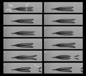
Figure 10. Detachment of a bubble with volume
 $V_{B}$
from a surface nucleus as a consequence of a Plateau–Rayleigh instability from the side view perspective. The time interval between the images is 2 ms. The flow is from left to right. The liquid is silicone oil with a kinematic viscosity of
$V_{B}$
from a surface nucleus as a consequence of a Plateau–Rayleigh instability from the side view perspective. The time interval between the images is 2 ms. The flow is from left to right. The liquid is silicone oil with a kinematic viscosity of
 $20\times 10^{-6}~\text{m}^{2}~\text{s}^{-1}$
and a capillary constant of
$20\times 10^{-6}~\text{m}^{2}~\text{s}^{-1}$
and a capillary constant of
 $21\times 10^{-3}~\text{kg}~\text{s}^{-2}$
. The surface nucleus and the detached bubble mirrors in the polished surface of the specimen.
$21\times 10^{-3}~\text{kg}~\text{s}^{-2}$
. The surface nucleus and the detached bubble mirrors in the polished surface of the specimen.
In Groß et al. (Reference Groß, Ludwig and Pelz2016) we presented experimental results gained in a similar experimental set-up using the same test section. In these experiments we used silicone oil with a kinematic viscosity of
 $20\times 10^{-6}~\text{m}^{2}~\text{s}^{-1}$
instead of water. The surface tension of the used silicone oil is
$20\times 10^{-6}~\text{m}^{2}~\text{s}^{-1}$
instead of water. The surface tension of the used silicone oil is
 $21\times 10^{-3}~\text{kg}~\text{s}^{-2}$
and the density is
$21\times 10^{-3}~\text{kg}~\text{s}^{-2}$
and the density is
 $945~\text{kg}~\text{m}^{-3}$
. Relatively large blind holes with a diameter of 0.8 mm worked as nucleation sites. The ratios of gap height to the diameter of the surface nucleus are
$945~\text{kg}~\text{m}^{-3}$
. Relatively large blind holes with a diameter of 0.8 mm worked as nucleation sites. The ratios of gap height to the diameter of the surface nucleus are
 $L/d=1.25$
and 3.75, respectively. Due to these small ratios, the fluid flow and thus the bubble detachment mechanism are influenced strongly. Nevertheless, we observed a detachment mechanism that might be of particular importance for some applications.
$L/d=1.25$
and 3.75, respectively. Due to these small ratios, the fluid flow and thus the bubble detachment mechanism are influenced strongly. Nevertheless, we observed a detachment mechanism that might be of particular importance for some applications.
Figure 10 shows twelve high-speed images of the detachment of a bubble from a surface nucleus in the side view perspective, cf. Groß et al. (Reference Groß, Ludwig and Pelz2016). The images illustrate that the detachment process is a consequence of a Plateau–Rayleigh instability (Rayleigh Reference Rayleigh1879). The detachment works as follows. The initial situation is a surface nucleus that expands over the edge of the bore and forms a cylindrical body. Small perturbations with different wavelengths that occur due to the fluid flow deform the cylindrical part of the nucleus. Deformations with wavelengths smaller than a critical wavelength increase the surface of the nucleus. Wavelengths larger than the critical wavelength lead to a reduction of the surface. Regarding to Rayleigh’s work principle, the nucleus is stable to deformations that increase the surface since work would have to be done. Deformations that decrease the surface will not be damped but increased because the system attempts to reach an energetically favourable state. For a cylindrical body with diameter
 $d_{c}$
with an infinite length the critical wavelength is its circumference
$d_{c}$
with an infinite length the critical wavelength is its circumference
 $\unicode[STIX]{x03C0}d_{c}$
(Rayleigh Reference Rayleigh1879).
$\unicode[STIX]{x03C0}d_{c}$
(Rayleigh Reference Rayleigh1879).
The largest wavelength that occurs approximately equals the length of the cylindrical part of the nucleus. The length of the nucleus, and thus the largest wavelength, increases while the surface nucleus is growing. The nucleus starts to oscillate up and down as soon as the critical length is reached. Since the perturbations are not attenuated, the cylindrical part of the surface nucleus deforms so strongly that it constricts and a bubble detaches. The Plateau–Rayleigh instability is a geometrical criterion. Of course, the bubble shape and the expansion over the edge of the bore are results of the acting forces.

Figure 11. (a) Volume of detached bubble versus shear rate. (b) Dimensionless bubble volume
 $\unicode[STIX]{x1D6FF}^{3}$
versus Weber number. The solid line is calculated with equation (2.19) and
$\unicode[STIX]{x1D6FF}^{3}$
versus Weber number. The solid line is calculated with equation (2.19) and
 $\unicode[STIX]{x1D716}_{III}=0.01$
. (c) Volume of detached bubble versus diameter of the cylindrical part of the surface nucleus. The solid line marks the critical volume
$\unicode[STIX]{x1D716}_{III}=0.01$
. (c) Volume of detached bubble versus diameter of the cylindrical part of the surface nucleus. The solid line marks the critical volume
 $V_{B}=\unicode[STIX]{x03C0}^{2}d_{c}^{3}/4$
. The open circles mark measurements with a gap height of 3 mm. The filled circles mark measurements with a gap height of 1 mm. The liquid is silicone oil with the properties
$V_{B}=\unicode[STIX]{x03C0}^{2}d_{c}^{3}/4$
. The open circles mark measurements with a gap height of 3 mm. The filled circles mark measurements with a gap height of 1 mm. The liquid is silicone oil with the properties
 $\unicode[STIX]{x1D71A}=945~\text{kg}~\text{m}^{-3}$
and
$\unicode[STIX]{x1D71A}=945~\text{kg}~\text{m}^{-3}$
and
 $S=21\times 10^{-3}~\text{kg}~\text{s}^{-2}$
.
$S=21\times 10^{-3}~\text{kg}~\text{s}^{-2}$
.
Figure 11 shows how the volume of the detached bubbles depends on the shear rate (graph a) as well as on the cylindrical part of the surface nucleus (graph c). As one expects, the volume of the detached bubbles decreases with increasing shear rate. The graphs illustrate that the detachment process depends only marginally on the gap height. Figure 11(a) also confirms the validity
 $Sr\propto WePe^{1/3}$
, equation (2.23) case III. The model implies
$Sr\propto WePe^{1/3}$
, equation (2.23) case III. The model implies
 $m_{B}\propto V_{B}\propto \dot{\unicode[STIX]{x1D6FE}}^{-2}$
, which can also be found in the graph. At first glance this finding is somehow surprising, since the detachment mechanism described here is not driven by forces but rather a stability limit based on surface energy. In fact, the growth of the nucleus and the formation of the shape follow the same physical law as the detachment mechanism described in § 2.2. The only difference is the trigger that causes the detachment (balance of forces or Rayleigh–Plateau instability). To underline this finding, figure 11(b) shows the dimensionless bubble volume
$m_{B}\propto V_{B}\propto \dot{\unicode[STIX]{x1D6FE}}^{-2}$
, which can also be found in the graph. At first glance this finding is somehow surprising, since the detachment mechanism described here is not driven by forces but rather a stability limit based on surface energy. In fact, the growth of the nucleus and the formation of the shape follow the same physical law as the detachment mechanism described in § 2.2. The only difference is the trigger that causes the detachment (balance of forces or Rayleigh–Plateau instability). To underline this finding, figure 11(b) shows the dimensionless bubble volume
 $\unicode[STIX]{x1D6FF}^{3}$
plotted against Weber number. The solid line is calculated with equation (2.19) and the dimensionless constant is determined as
$\unicode[STIX]{x1D6FF}^{3}$
plotted against Weber number. The solid line is calculated with equation (2.19) and the dimensionless constant is determined as
 $\unicode[STIX]{x1D716}_{III}=0.01$
. One clearly sees that the experimental results are well described by the asymptote
$\unicode[STIX]{x1D716}_{III}=0.01$
. One clearly sees that the experimental results are well described by the asymptote
 $\unicode[STIX]{x1D6FF}^{3}=(\unicode[STIX]{x1D716}_{III}We)^{-1}$
.
$\unicode[STIX]{x1D6FF}^{3}=(\unicode[STIX]{x1D716}_{III}We)^{-1}$
.
It should be noted that the value of
 $\unicode[STIX]{x1D716}_{III}$
is very small compared to the values of
$\unicode[STIX]{x1D716}_{III}$
is very small compared to the values of
 $\unicode[STIX]{x1D716}_{II}$
discussed in the previous section. This is due to an overestimation of the dynamic force in the present case. The surface nucleus shows an ‘streamlined’ shape leading to a reduction of drag. Hence, it is not surprising that
$\unicode[STIX]{x1D716}_{II}$
discussed in the previous section. This is due to an overestimation of the dynamic force in the present case. The surface nucleus shows an ‘streamlined’ shape leading to a reduction of drag. Hence, it is not surprising that
 $\unicode[STIX]{x1D716}_{III}$
has a relatively small value.
$\unicode[STIX]{x1D716}_{III}$
has a relatively small value.
Figure 11(c) illustrates how the volume of the detached bubbles increases with increasing diameter of the cylindrical part of the nucleus. As mentioned before, the surface nucleus becomes unstable when it reaches a critical size, and perturbations with wavelengths larger than its diameter occur. The straightforward approach to calculate the volume of the detached bubbles is to calculate the volume of a cylinder whose length equals its circumference,
 $V_{B}=\unicode[STIX]{x03C0}^{2}d_{c}^{3}/4$
. The solid line in figure 11(c) represents this calculation. The volume of the detached bubble is proportional to the cube of the diameter of the cylindrical part. The measured values lie only slightly above the solid line.
$V_{B}=\unicode[STIX]{x03C0}^{2}d_{c}^{3}/4$
. The solid line in figure 11(c) represents this calculation. The volume of the detached bubble is proportional to the cube of the diameter of the cylindrical part. The measured values lie only slightly above the solid line.
Our experiments with water and silicone oil demonstrate that there are a variety of detachment mechanisms that might occur, cf. figures 8 and 10. At first sight, the Plateau–Rayleigh instability seems not to be of practical importance, especially for water flows. However, there is experimental evidence that this detachment mechanism also occurs in hydrodynamic cavitation. Guennoun (Reference Guennoun2006) observed the detachment of bubbles from a surface nucleus attached to a surface irregularity (see figure 4.7 of his work). The detachment behaviour looks very similar to the behaviour described here (Martijn van Rijsbergen, personal communication, February 2, 2016).
5 Application to technical flow problems
In the previous sections we demonstrated that nucleation rates can be calculated on the basis of the approach
 $f={\dot{m}}/m_{B}$
. We showed that the three correlations
$f={\dot{m}}/m_{B}$
. We showed that the three correlations
 $Sr\propto \unicode[STIX]{x1D701}We^{1/3}Pe^{1/3}$
,
$Sr\propto \unicode[STIX]{x1D701}We^{1/3}Pe^{1/3}$
,
 $Sr\propto \unicode[STIX]{x1D701}We^{3/4}Pe^{1/3}$
and
$Sr\propto \unicode[STIX]{x1D701}We^{3/4}Pe^{1/3}$
and
 $Sr\propto \unicode[STIX]{x1D701}WePe^{1/3}$
are useful to calculate nucleation rates occurring at micro crevices. To underline the importance of our findings we discuss our approach using examples of practical interest.
$Sr\propto \unicode[STIX]{x1D701}WePe^{1/3}$
are useful to calculate nucleation rates occurring at micro crevices. To underline the importance of our findings we discuss our approach using examples of practical interest.
First, we want to take a look on the streak cavitation experiments conducted in Lausanne, cf. figure 2. The theoretical findings indicate that the shear rate plays a crucial role in the described nucleation process. The shear rate on a hydrofoil can be determined using the theory for the evolution of the boundary layer thickness on a flat plate,
 $\unicode[STIX]{x1D6FF}_{U}=5x/Re_{x}^{1/2}$
with coordinate
$\unicode[STIX]{x1D6FF}_{U}=5x/Re_{x}^{1/2}$
with coordinate
 $x$
, Reynolds number
$x$
, Reynolds number
 $Re_{x}=U_{\infty }x/\unicode[STIX]{x1D708}$
and velocity of the undisturbed flow
$Re_{x}=U_{\infty }x/\unicode[STIX]{x1D708}$
and velocity of the undisturbed flow
 $U_{\infty }$
(Schlichting & Gersten Reference Schlichting and Gersten2006). Using
$U_{\infty }$
(Schlichting & Gersten Reference Schlichting and Gersten2006). Using
 $\dot{\unicode[STIX]{x1D6FE}}\approx U_{\infty }/\unicode[STIX]{x1D6FF}_{U}$
we get
$\dot{\unicode[STIX]{x1D6FE}}\approx U_{\infty }/\unicode[STIX]{x1D6FF}_{U}$
we get
 $\dot{\unicode[STIX]{x1D6FE}}\approx 1/5\sqrt{U_{\infty }^{3}/(x\unicode[STIX]{x1D708})}$
. Guennoun et al. (Reference Guennoun, Farhat, Bouziad and Avellan2003) conducted experiments with
$\dot{\unicode[STIX]{x1D6FE}}\approx 1/5\sqrt{U_{\infty }^{3}/(x\unicode[STIX]{x1D708})}$
. Guennoun et al. (Reference Guennoun, Farhat, Bouziad and Avellan2003) conducted experiments with
 $U_{\infty }=20~\text{m}~\text{s}^{-1}$
and observed nucleation at
$U_{\infty }=20~\text{m}~\text{s}^{-1}$
and observed nucleation at
 $x=1~\text{mm}$
. At the nucleation site the shear rate has a value of
$x=1~\text{mm}$
. At the nucleation site the shear rate has a value of
 $5.7\times 10^{5}~\text{s}^{-1}$
, and is thus two orders of magnitude larger than the shear rates observed in our experiments. Guennoun observed nucleation rates of up to 5 kHz. Using
$5.7\times 10^{5}~\text{s}^{-1}$
, and is thus two orders of magnitude larger than the shear rates observed in our experiments. Guennoun observed nucleation rates of up to 5 kHz. Using
 $f={\dot{m}}/m_{B}$
and the correlation for the mass flux equation (2.13) one obtains a bubble diameter of
$f={\dot{m}}/m_{B}$
and the correlation for the mass flux equation (2.13) one obtains a bubble diameter of
 $d_{B}\approx 18.1~\unicode[STIX]{x03BC}\text{m}$
for a moderate supersaturation of
$d_{B}\approx 18.1~\unicode[STIX]{x03BC}\text{m}$
for a moderate supersaturation of
 $\unicode[STIX]{x1D701}=1$
. The bubble diameter increases with
$\unicode[STIX]{x1D701}=1$
. The bubble diameter increases with
 $\unicode[STIX]{x1D701}^{1/3}$
(
$\unicode[STIX]{x1D701}^{1/3}$
(
 ${\mathcal{R}}=8.314~\text{J}~(\text{mol}~\text{K})^{-1}$
,
${\mathcal{R}}=8.314~\text{J}~(\text{mol}~\text{K})^{-1}$
,
 $T=293.15~\text{K}$
,
$T=293.15~\text{K}$
,
 ${\mathcal{H}}=7.4\times 10^{-6}~\text{mol}~(\text{m}^{3}~\text{Pa})^{-1}$
). On the basis of (2.23) and assuming a case III detachment we obtain
${\mathcal{H}}=7.4\times 10^{-6}~\text{mol}~(\text{m}^{3}~\text{Pa})^{-1}$
). On the basis of (2.23) and assuming a case III detachment we obtain
 $\unicode[STIX]{x1D716}_{III}=3.67\times 10^{-2}$
with
$\unicode[STIX]{x1D716}_{III}=3.67\times 10^{-2}$
with
 $We=4.6\times 10^{6}$
. This value is surprisingly close to the value of
$We=4.6\times 10^{6}$
. This value is surprisingly close to the value of
 $\unicode[STIX]{x1D716}_{III}=10^{-2}$
determined in the previous section. In the light of this finding a case III detachment seems to be unlikely in the case of micro crevices, due to the large required shear rates.
$\unicode[STIX]{x1D716}_{III}=10^{-2}$
determined in the previous section. In the light of this finding a case III detachment seems to be unlikely in the case of micro crevices, due to the large required shear rates.
A second practical application of our model is a plausibility check of Euler–Lagrange simulations of cavitating flows where surface nucleation is considered. Recent computational fluid dynamics (CFD) studies on sheet and cloud cavitation underline the relevance of nucleation in the context of hydrodynamic cavitation. Chahine and his group (e.g. Hsiao, Ma & Chahine Reference Hsiao, Ma and Chahine2014; Chahine Reference Chahine2015; Ma, Hsiao & Chahine Reference Ma, Hsiao and Chahine2015) investigated sheet and cloud cavitation using an Euler–Lagrange model where cavitation nuclei and their bubble dynamics are considered. The nuclei are created at nucleation spots on the surface of the investigated objects. The authors used a nucleation rate of 22 kHz in their simulations. The model works without any empirical mass exchange models that are non-physical and need to be calibrated. Although this approach is computationally expensive in comparison to other cavitation models (e.g. Schnerr & Sauer Reference Schnerr and Sauer.2001; Singhal et al.
Reference Singhal, Li, Athavale and Jiang2001), it is physically more consistent for representing the processes of sheet and cloud cavitation. Since there is only a little influence of the bubble radius on the numerical results, the predefined initial bubble radius is set to be
 $10~\unicode[STIX]{x03BC}\text{m}$
. The nucleation rate and the initial nuclei radius used in the simulations are not experimentally validated. One has to keep in mind that the size of the nucleation spots are of the order of magnitude of the surface roughness or the size of surface irregularities (e.g. shrinkage cavities), and thus of orders of magnitude from 0.1 to
$10~\unicode[STIX]{x03BC}\text{m}$
. The nucleation rate and the initial nuclei radius used in the simulations are not experimentally validated. One has to keep in mind that the size of the nucleation spots are of the order of magnitude of the surface roughness or the size of surface irregularities (e.g. shrinkage cavities), and thus of orders of magnitude from 0.1 to
 $10~\unicode[STIX]{x03BC}\text{m}$
. It would be very unlikely that the diameters of the detaching bubbles are orders of magnitude larger than the size of the nucleation spots for the large shear rates and large nucleation rates occurring in cavitating flows. We can use our model to check the predefined bubble diameter on plausibility.
$10~\unicode[STIX]{x03BC}\text{m}$
. It would be very unlikely that the diameters of the detaching bubbles are orders of magnitude larger than the size of the nucleation spots for the large shear rates and large nucleation rates occurring in cavitating flows. We can use our model to check the predefined bubble diameter on plausibility.
Assuming a nucleation spot with
 $d=10~\unicode[STIX]{x03BC}\text{m}$
we can use equation (2.13) to calculate a shear rate of
$d=10~\unicode[STIX]{x03BC}\text{m}$
we can use equation (2.13) to calculate a shear rate of
 $1.2\times 10^{18}~\text{s}^{-1}$
for a moderate supersaturation of 1. This shear rate is unphysically large. We now use equation (2.23) with
$1.2\times 10^{18}~\text{s}^{-1}$
for a moderate supersaturation of 1. This shear rate is unphysically large. We now use equation (2.23) with
 $\unicode[STIX]{x1D716}_{II}=5\times 10^{2}$
, cf. figure 9, and calculate the shear rate for a case II detachment to be
$\unicode[STIX]{x1D716}_{II}=5\times 10^{2}$
, cf. figure 9, and calculate the shear rate for a case II detachment to be
 $\dot{\unicode[STIX]{x1D6FE}}\approx 1.3\times 10^{6}~\text{s}^{-1}$
, which is still large (the properties of the liquid are listed above). The Weber number then is
$\dot{\unicode[STIX]{x1D6FE}}\approx 1.3\times 10^{6}~\text{s}^{-1}$
, which is still large (the properties of the liquid are listed above). The Weber number then is
 $We\approx 25.3$
. Equation (2.18) then gives a bubble diameter of
$We\approx 25.3$
. Equation (2.18) then gives a bubble diameter of
 $d_{B}\approx 0.9~\unicode[STIX]{x03BC}\text{m}$
, which is small but a more reliable value than
$d_{B}\approx 0.9~\unicode[STIX]{x03BC}\text{m}$
, which is small but a more reliable value than
 $20~\unicode[STIX]{x03BC}\text{m}$
. In summary, diffusion-driven nucleation of bubbles with a diameter of
$20~\unicode[STIX]{x03BC}\text{m}$
. In summary, diffusion-driven nucleation of bubbles with a diameter of
 $20~\unicode[STIX]{x03BC}\text{m}$
with a frequency of 22 kHz seems implausible in the light of our findings.
$20~\unicode[STIX]{x03BC}\text{m}$
with a frequency of 22 kHz seems implausible in the light of our findings.
In our model we only consider single surface nuclei sitting in a well-defined crevice. In technical applications there are an uncountable number of nucleation spots located on a surface with a variety of geometries, e.g. steps (Pelz et al. Reference Pelz, Keil and Ludwig2014), surface irregularities or roughness elements (van Rijsbergen & van Terwisga Reference van Rijsbergen and van Terwisga2011). In Pelz et al. (Reference Pelz, Keil and Groß2017) we discussed the nucleation process in the context of sheet and cloud cavitation originating from an artificial roughness. Taking into consideration that free-stream nuclei ‘activate’ the artificial roughness and form a large liquid–gas interface, one can conclude that diffusion-driven nucleation is responsible for the production of the vast number of bubbles forming the sheet cavity. Large shear rates together with a sufficiently large liquid–gas interface are the key elements here.
Of course, the process of diffusion-driven nucleation in technical flows is a very complex phenomenon. Different nucleation sites on surfaces could interact with each other, and could combine and form a larger surface nucleus. In addition, detaching bubbles could influence each other or could cause the bubble detachment at surface nuclei further downstream. The nucleation process is influenced by an usually unknown local supersaturation and might be affected by the wettability of the surface. Furthermore, the surface tension and the vapour pressure of the liquid could play an important role as well as turbulence and vortex formation. This work can serve as a first step for further investigations on diffusion-driven nucleation in the context of hydrodynamic cavitation. In the light of the findings presented, the role of diffusion must be reassessed.
6 Conclusion
There is no doubt that free-stream nuclei and surface nuclei play an important role for the inception and appearance of cavitating flows. Cavitation nuclei work as weak spots in the liquid and allow its rupture under technically relevant pressures. The theories and models of nuclei and their stabilisation are well established and recognised in the cavitation community. Nevertheless, there is a lack of knowledge about the principles of diffusion-driven nucleation from surface nuclei in the context of hydrodynamic cavitation. In the present paper we investigate the formation of bubbles that might serve as cavitation nuclei at pre-existing gas cavities (surface nuclei) in a supersaturated liquid due to gas diffusion. The produced bubbles might act as cavitation nuclei when entering a low-pressure region.
The self-excited cyclic process of diffusion-driven nucleation is analysed and new theoretical considerations are presented and validated with experimental results. The nucleation rate is expressed as the ratio of the mass flux that diffuses into the surface nucleus and the mass of the detaching bubbles,
 $f={\dot{m}}/m_{B}$
. Therefore, it is expedient to treat these two aspects, i.e. the two phases of the cyclic process, separately. The mass transfer is modelled by solving an advection–diffusion equation while the bubble detachment is treated with a balance of forces. The first model shows that the mass transfer is intensified by the fluid flow, as one expects. The dimensionless mass transfer (Sherwood number) is proportional to the Péclet number to the power of one third and depends linearly on the supersaturation of the liquid
$f={\dot{m}}/m_{B}$
. Therefore, it is expedient to treat these two aspects, i.e. the two phases of the cyclic process, separately. The mass transfer is modelled by solving an advection–diffusion equation while the bubble detachment is treated with a balance of forces. The first model shows that the mass transfer is intensified by the fluid flow, as one expects. The dimensionless mass transfer (Sherwood number) is proportional to the Péclet number to the power of one third and depends linearly on the supersaturation of the liquid
 $\unicode[STIX]{x1D701}$
. The second model shows that the size of the detaching bubbles is a function of the Weber number. Depending on the detachment mechanism one obtains three asymptotes
$\unicode[STIX]{x1D701}$
. The second model shows that the size of the detaching bubbles is a function of the Weber number. Depending on the detachment mechanism one obtains three asymptotes
 $Sr\propto \unicode[STIX]{x1D701}\unicode[STIX]{x1D6EC}We^{n}Pe^{1/3}$
with
$Sr\propto \unicode[STIX]{x1D701}\unicode[STIX]{x1D6EC}We^{n}Pe^{1/3}$
with
 $n=1/3,3/4,1$
for the nucleation rate with dimensionless gas solubility
$n=1/3,3/4,1$
for the nucleation rate with dimensionless gas solubility
 $\unicode[STIX]{x1D6EC}$
. The results of the calculation are in good agreement with experimental findings gained in generic experiments. The models serve well for the analysis of streak cavitation. In addition, the models can be used to check the plausibility of nucleation rates and bubble diameters used in Euler–Lagrange simulations of cavitating flows. The transfer of the findings to other cavitation regimes such as sheet and cloud cavitation is conceivable. The discussion about diffusion-driven nucleation leads to a new assessment of the role of diffusion in hydrodynamic cavitation.
$\unicode[STIX]{x1D6EC}$
. The results of the calculation are in good agreement with experimental findings gained in generic experiments. The models serve well for the analysis of streak cavitation. In addition, the models can be used to check the plausibility of nucleation rates and bubble diameters used in Euler–Lagrange simulations of cavitating flows. The transfer of the findings to other cavitation regimes such as sheet and cloud cavitation is conceivable. The discussion about diffusion-driven nucleation leads to a new assessment of the role of diffusion in hydrodynamic cavitation.
Acknowledgements
We would like to thank Professor Dr F. Peters (Ruhr-Universität Bochum), for valuable hints regarding the experimental set-up, and Dr D. Fernandez Rivas (Mesoscale Chemical Systems group, University of Twente), who supplied us with the silicon wafers.


 Open access