
Abstract
Fabrication results for MEMS-based microneedle arrays are presented in this paper. The microneedle array was fabricated by employing a bi-mask technique to facilitate sharp tips, a cylindrical body and side openings. The presented array has advantages over previously published microneedle arrays in terms of ease of fabrication and bonding; high needle density and robustness; and side openings, which are expected to minimize the potential for clogging from skin debris during insertion. In addition, control over the process via etch-stop markers employed as stop layers, which assure the depth of long blind holes and the structure of the needle top, allows for different needle lengths and needle top structures to be easily implemented. The preliminary fluid flow and insertion experiments were performed to demonstrate the efficiency of the microneedle arrays.
1 Introduction
1.1 Needles and microneedles
Hollow needles, since they were invented in 1844 (The World Book Encyclopedia 1999), have played an increasingly important role in biological fluid extraction and drug delivery systems. There are no other effective methods to extract fluid and they do not have the orally administered drug disadvantages of degradation in the gastrointestinal tract and/or elimination by the liver (McAllister et al. 2000).
Although fluid extraction and drug delivery can be accomplished by hollow needles, there are also significant disadvantages including: insertion pain; tissue trauma; difficulty in providing sustained drug release; and the need for expertise to perform an injection.
“Needle phobia” causes many people to avoid visiting their physicians. As reported in (Hamilton 1995), more than ten percent of the population of the US suffers from “needle phobia”, although far more than ten percent have a severe anxiety towards receiving injections. Microneedles promise to play an important role in providing a greater level of comfort to patients with such phobias; not only in alleviating discomfort but also in providing accurate control of complex drug delivery requirements (Pinkerton 2004).
The blood and cellular interstitial fluid contain metabolic and immunological biomolecules whose varying concentrations as a function of time can indicate the various states of health and disease. The most effective method for sampling biological fluids is carried out by invasive techniques; however, periodic or continuous monitoring using hypodermic needles is not practical outside of a hospital or clinical setting due to tissue trauma, patient discomfort, the need for specialized medical knowledge and the potential for infection (Sieg et al. 2005).
In addition, bolus injections can lead to high concentrations of drugs being injected into the body and blood stream with the potential of toxic side effects. The need for new drug delivery routes and microbiological sampling has been recognized for some time, especially for new biotechnology drugs that cannot be administered using conventional approaches (Langer 1998).
Microneedles and microneedle arrays are capable of providing pathways for drug delivery or fluid extraction across the skin (Zhang et al. 2009), and offer several advantages when compared to conventional needle technologies including: being minimally invasive due to their small cross-sectional area; providing precise penetration depth under the skin by controlling the length of the microneedle or making penetration stops at the needle body (Chandrasekaran et al. 2003); inducing minimal trauma and opportunities for infection during insertion due to the advanced tip designs (Reed and Lye 2004), increased functionality and the potential for stand alone automated delivery/extraction devices.
Microneedle technology promises to impact health care by allowing the precise injection of therapeutic agents to prescribed locations below the skin. Since microneedles are capable of penetrating the stratum corneum (the first layer of skin) but not in penetrating deep enough into the dermis to cause noticeable pain, or are too small to significantly stimulate nerve endings, they are expected to provide almost painless drug delivery (Kaushik et al. 2001). Microneedles, in particular arrays of such needles, have many potential applications in different areas of medicine and biology, such as vaccinations (Mikszta et al. 2002), transportation of DNA (Chabri et al. 2004), diabetes and cancer treatment (Drum 1996; Smart and Subramanian 2000). Side opened microneedles are of particular importance, as standard tip microneedles are prone to having tissue clog the opening during insertion. In our design, the size of the side opening can be varied to control the drug exposure area.
1.2 Microneedle fabrication techniques
Research on microneedles dates back at least to a publication by Najafi and Wise in 1985 (Najafi et al. 1985; Najafi and Wise 1986). The earliest microneedles were fabricated using solid silicon, and these needles were used as microprobes for neural electrical activity recording. Since the publication of that work, a variety of micromachined needle designs have been reported (e.g., Prausnitz 2004; Kabseog et al. 2004). Many different approaches have been employed, including surface micromachining (Lin et al. 1993; Lin and Pisano 1999), bulk micromachining (Chen and Wise 1994; Mukerjee et al. 2004), and LIGA techniques, and many materials have been used including silicon (Prausnitz 2004), silicon nitride (Lin and Pisano 1999), silicon dioxide (Mukerjee et al. 2004), metal (Brazzle et al. 1998), polymer (Kuo and Chou 2004), and others (Khumpuang and Susumu 2004).
At present, the microneedle designs reported in the literature can be classified into two types: in-plane and out-of-plane. Microneedles are in-plane if the longitudinal axis of the needles is parallel to the wafer, and out-of-plane if the longitudinal axis of the needles is normal to the wafer.
The hollow silicon microneedle, reported by Lin, Pisano and Muller (Lin et al. 1993; Lin and Pisano 1999), was fabricated with a silicon nitride shell on top of a silicon substrate. Chen and Wise fabricated hollow microneedles using a buried channel process in the silicon substrate employing surface and bulk micromachining techniques (Chen and Wise 1994; Mukerjee et al. 2004). Hollow microneedles can be also built with metal (Brazzle et al. 1998), polymer (Kuo and Chou 2004) and other materials (Khumpuang and Susumu 2004). All the microneedles discussed above are in-plane. For in-plane microneedles, a large needle length is easy to achieve, but the needle density is limited, and the microchannel volume is usually very small relative to the total volume of the support silicon.
Henry et al. (1998) developed a process for the fabrication of arrays of short, vertically oriented (out-of-plane) solid microneedles. Prausnitz et al. (1999) used the solid microneedles described above as a template to form a mold made of SU-8 thick photoresist. Hollow needles were then fabricated by electroplating NiFe onto the mold. However, these needles had irregularly shaped tips, and the fluid outlet was at the tip of the needle, which increases its potential to clog when inserted into tissue (the tip cuts out a piece of tissue that then clogs the opening). Stoeber fabricated arrays of microneedles out of silicon but the needle base was relatively large (Stoeber and Liepmann 2000a, b). An improved needle design, based on Stoeber’s work, was reported by Gardeniers et al. (2002, 2003); however, the potential problem of clogging still existed since the outlet was at the needle tip. In order to solve this problem, Griss and Stemme (2002, 2003) reported on the fabrication of microneedles featuring a side opening, formed using an isotropic plasma etch. Although the fabrication process is quite straightforward, there is a potential issue with the top mask used in the process, which may fall off and stick to a side-wall. Such an occurrence could lead to errors in the fabrication of the side-ports. In addition, the side openings cannot be easily controlled as their fabrication uses isotropic etching, which can affect the etching of surrounding structures. Also, in our estimation, due to the needle channels being deep and blind holes, during processing the depths of these channels can only be estimated according to etching time. Therefore, the structure and strength of the needle top cannot be fabricated with any degree of certainty or reliability.
In this paper, the design, fabrication and characterization of out of plane microneedle arrays that considerably improve upon the work reported by Griss and Stemme (2003), are presented, along with preliminary fluid flow test results through the arrays. The microneedle arrays are fabricated by employing a novel bi-mask technique to facilitate very sharp tips with keen edges, a cylindric body and side openings. Test results are compared to published work and experimentally tested to demonstrate that the fabrication route is adaptable and the needle array is robust.
2 Design and modeling
2.1 Microneedle features
An understanding of skin anatomy is required in order to determine appropriate dimensions and structures of microneedles. The human skin is comprised of three primary layers; the stratum corneum, viable epidermis and dermis (Champion et al. 1992). The dermis is in close contact with blood vessels and nerves. The viable epidermis is approximately 50–100 μm thick, composed of living cells but void of blood vessels and containing few nerves. The stratum corneum, the outermost layer of skin, is 10–15 μm thick, is primarily made of dead tissue and provides the primary barrier to penetration or transport. This signifies that a microneedle which can penetrate the stratum corneum (10–15 μm) but is shorter than 50–100 μm, may provide pathways for drug delivery without pain (Kaushik et al. 2001). For obtaining blood samples the needles should be greater than 100 μm in length in order to reach the dermis. The small dimensions of microneedles promise to provide relatively painless minimal invasion, and reduced damage to the skin. The opportunity of infection should also be considerably decreased.
The microneedle structure mainly defines the needle’s properties. Due to the small dimensions of the microneedles, the fluid contained in the channel has a low volume, but high needle density in an array can compensate for this and also increase the fluid flow rate; this is a current issue with individual microneedles. The needle density issue implies that an out of plane microneedle array design is to be preferred. Another issue is the choice of fabrication material. Briefly: silicon dioxide is fragile; the strength of metal is much better, but thin films of metal formed by sputtering or evaporation are soft. The mechanics of microneedle insertion are also critically important for practical applications. Sharper needle tips can be expected to require less force for insertion, but the reduced penetration force comes at the expense of reduced strength near the needle tip. Obviously, only microneedles with appropriate geometry and physical properties are able to penetrate the skin without breaking or bending during insertion.
The geometries of the needle tip have a great effect on the forces required for insertion and fracture. Insertion force can be shown to be independent of wall thickness; thin-walled hollow needles and solid needles with the same outer tip radii require the same insertion force (Davis et al. 2004). Fracture force increases with increasing wall thickness and decreases with increasing wall angle, but is independent of tip radius (Davis et al. 2004). Therefore, needles with a small tip radius and large wall thickness are considered the best option. Also, the blockage (clogging) problem that can occur upon insertion must be taken into consideration when designing microneedle structures. For example, it is assumed that blockages are more likely to occur when the inlet or outlet is on the tip of the needle.
2.2 Microneedle design
We present a modified microneedle array, based on the work reported in (Griss and Stemme 2003; Zhang and Jullien 2003), that attempts to address all of the issues discussed above. The basic structure of the microneedle array is shown in Fig. 1.

Structure of the microneedle array
In order to realize a reliable side port design, and to be able to place the tip on the top of a cylindrical needle base rather than directly on the wafer surface, the fabrication process employs a bi-mask technique (Zhang and Jullien 2003, 2005), which fabricates two levels of etching masks (Mask A followed by Mask B) prior to the actual etching procedure. The etching process takes place by first using Mask B to sculpt the wafer, this mask is then removed exposing Mask A which is then used for a subsequent etching procedure (see Fig. 5e and the full process description in Sect. 3). This technique allows the first mask to be patterned on a flat wafer surface (a reliable process) rather than on a sculpted surface, which would prove to be a much more difficult task.
The overall design has the following characteristics:
-
The side ports of the needle are obtained by direct anisotropic etching, which is easy to control, repeatable and reliable. The isotropic etching in (Griss and Stemme 2002) is more difficult to control as the dimensions of the openings are defined by the etching time, which is affected by the etching of other structures before hand.
-
The shape of the side pillars on the top has a knife-like edge. This shape not only pierces the skin more easily (helping to avoid the clogging issue), but also has potential to reduce the damaged tissue area compared to other designs because of the submicron size and the knife-like edge.
-
The shape of the side pillars can be controlled more easily during the subsequent isotropic etching process since the needle wall is not etched during this etching step. To obtain the shape of the side pillars in (Griss and Stemme 2002) the isotropic etching time has to be strictly controlled. Thus there will be problems in obtaining a smooth etch if there are errors in the etching time; for example, the needle wall will be etched at the same time.
-
The bi-mask technique eliminates the potential problem caused by a dropping mask during the etching procedures, which could be an issue in (Griss and Stemme 2002) Using the bi-mask technique, the side-ports are directly obtained by an anisotropic etch, avoiding the possibility that the side ports can not be obtained due to falling mask, as stated in (Griss and Stemme 2002).
-
As a cylindrical body is formed below the microneedle tip, leakage from the side ports is controlled since the tip is guaranteed to be completely embedded in the tissue.
-
The cylindrical needle body also eliminates stress concentration, allowing for a strong needle structure.
-
The cylindrical needle body has better self-adhesion (to hold the needle in place) when inserted into elastic tissue, minimizing the requirement for holding the needle array in place by other means.
-
The thickness of the needle body is defined by the mask, not controlled by etching time, unlike the fabrication process discussed in (Griss and Stemme 2002).
3 Fabrication
The microneedle array fabrication process flow is shown in Fig. 2. The microneedle array fabrication process was simulated using the Intellisuite package (IntelliSense Software Corp.) to confirm the feasibility of the process before continuing with actual fabrication.

Process flow of the microneedle fabrication
In the first step, an oxide layer is thermally grown onto a silicon wafer and patterned (Fig. 2a). Holes are then anisotropically etched by RIE into the front side of the wafer (Fig. 2b). These holes will be used as etch-stop markers for the next etching step. A thin film of SiO2 is then deposited onto the backside of the wafer by using LPCVD. The SiO2 is then patterned to form holes for both the microneedle channels and the etch-stop markers (Fig. 2c). The channels are then anisotropically etched by deep RIE from the backside of the wafer, as shown in Fig. 2d. The etching continues until the special marker channels are exposed. The marker channels are etched along with the needle channels, but they etch through to a previous surface etch (on the order of 20 μm below the original wafer surface) on the front of the wafer. At this step, the depth of the needle channels, as blind holes, are the same as the depth of the anisotropic etch (Fig. 2b). After the SiO2 is removed (either by wet etching or RIE) the wafer is given another thermal growth of oxide. The next step is forming the bi-mask structure (Fig. 2e), which is aligned to the center of the hole on the front side of the wafer. An anisotropic ICP step follows, forming the body of the needle. Then, the wafer is given another thermal growth of oxide (Fig. 2f), which forms a thin film of SiO2 on the surface of both needle bodies and channels and is used to protect both the needle bodies and channels during the subsequent steps, thereby ensuring the needle thickness. After the upper mask from the bi-mask is removed by RIE, the wafer is isotropically etched using ICP (Fig. 2g). Following that, a second anisotropic ICP is carried out. During this step, the side ports are formed (Fig. 2h). In order to guarantee a sharp needle tip, a third isotropic ICP is employed (Fig. 2i). Finally, the SiO2 is etched (Fig. 2j), and the processing is complete. Several microneedle arrays were fabricated at Micralyne Inc., Edmonton, Alberta, Canada, through a special Province of Alberta grant. Figure 3 shows the SEM of one of the fabricated microneedle arrays. The needle array is 3 × 3 millimeters, containing 110 needles in a 10 × 11 configuration. The needles are 200 μm long with an internal diameter of 40 μm and three side openings of 28 by 50 μm2 each. The tip of the needle is extremely sharp, having submicron dimensions of approximately 450 nm, as is clearly shown in Fig. 3a.

The microneedle array
4 Test results
In order to verify the efficiency of the microneedles for biological media transport, three tests were performed. The first test was to insert the array into the skin of a potato, to demonstrate the passive utility of the array to extract liquid using capillary forces alone. Potato liquid extraction was observed from below the skin of a potato, using the needle capillary forces; this preliminary data was reported previously (Zhang and Jullien 2005). The second test was more quantitative, in which the microneedle array flow properties were measured using water. The water flowed out through the microneedle array, as shown in Fig. 4. Using a 3 × 3 mm2 array, containing 110 microneedles, a range of flow rates was tested, starting at 50 μl/s and increasing to 600 μl/s. This test demonstrates the practical utility of the microneedle array to inject significant quantities of liquid into a small area, suitable for many applications such as drug delivery (Neeves et al. 2006). The third test was to demonstrate fluid injection by delivering a different fluid, in this case blue-black ink, under the skin of a chicken thigh, as shown in Fig. 5. Chicken skin has been used as suitable biological simulation of human skin by many authors, and some investigations have shown that drugs can be delivered to the skin capillaries by hollow microneedles (Stoeber and Liepmann 2000a, b; Klein 2006; Trautmann et al. 2003; Kampuang et al. 2003; Sammoura et al. 2007; Sivamani et al. 2005). As can be clearly seen in Fig. 5, the ink was successfully injected through the chicken skin and penetrated, by capillary action, into the chicken thigh flesh by ~500 μm. There is more ink injected to the left hand side of the injection region than the right due to non-uniform contact of the array to the skin. Due to the elastic nature of skin, this could be an issue for correctly metering dosages, and more research should be performed to clarify this effect, and also to investigate the most practical locations on a patient to ensure maximum penetration. Upon removal of the array, excess ink spread out over the surface of the chicken skin. This undesirable effect can easily be overcome by metering precise quantities of liquid for any given application, and preventing flow before array removal. Upon microscope inspection afterwards, no broken or damaged microneedles were found. Also, by viewing the spots of light through the array from behind, no clogged microneedles were discovered, proving the utility of the tip protection and side port approach.

Delivery test, showing a droplet formed on the end of the array

Ink injection test through chicken skin a macro image showing the needle edges visible under the end of a nanoport and b the cross-sectional image of the chicken skin and flesh after ink injection
5 Discussion
Microneedles promise relatively painless drug delivery, functionality and other advantages as mentioned above. The microneedle array reported here is comparatively easy to fabricate, and the dimensions of each needle can be controlled reliably by changing the etch times. As an example of changing etch times, Fig. 6 shows a deliberately over-etched array, where the side supports at the top of needle body are even more knife-like, which will provide easier piercing and lower tissue trauma. Although this particular sample was over-etched, thus weakening the needle, sufficient strength can be obtained while maintaining the sharper point using etch-stop holes, and this shows the versatility of the fabrication method—application specific microneedle designs can be implemented with the same process and the same masks.

Microneedle array II, showing over etched tips which are structurally weaker that those shown in Fig. 3, but which have different insertion properties
The main features of the microneedle array design presented in this paper are provided below, along with a comparison to the design given in (Griss and Stemme 2002).
-
1.
It is an out-of-plane structure with submicron dimensions (~450 nm).
-
2.
There is a flexible needle density, which is specified by the initial masking steps.
-
3.
The microneedles are made of single crystalline silicon which, along with the cylindrical needle body, provides high resistance to bending and shearing.
-
4.
The microneedle side ports are expected to minimize the potential for clogging by skin debris during insertion, as indicated by the chicken skin tests.
-
5.
The array offers a large area of fluid exposure to the tissue, compared to the in-plane microneedle (Lin et al. 1993).
-
6.
The microneedle has an extremely sharp tip and the knife-like edges allow easy penetration of the skin.
-
7.
The backside can be easily bonded with sensors, reservoirs and the like, because the backside of the wafer only undergoes a small amount of processing. There is a considerable amount of literature available on microvalves (Oh and Ahn 2006), and it is possible that different sections of the microneedle array can have independent valving on the backside of the wafer, allowing for time delayed drug delivery, or even different drugs being administered via different microneedle sections.
-
8.
The 2-D structure can stretch the skin omnidirectionally for easier penetration.
-
9.
The cylindrical needle body has the potential to produce self-adhesion frictional forces when inserted into elastic skin, which will contract onto the needle body, thus minimizing the need for holding the needle in place by some external force (Mukerjee et al. 2004). The cylindrical body also provides the microneedles with a greater ability to resist shear force than the structures described in (Griss and Stemme 2002), which result in stress concentration at the needle body, as highlighted in Fig. 7, where the thickness of the needle wall, as referenced in (Griss and Stemme 2002), has changed shape, which causes stress concentration at the point indicated.
Fig. 7 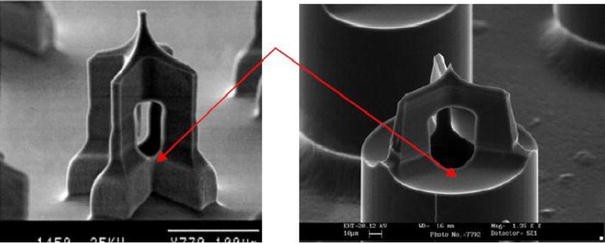
Structure comparisons; the arrow highlights the difference in the side openings. a Structure in reference (Griss and Stemme 2002) b structure in this work
-
10.
In our design, the needle body is cylindrical and the thickness can be easily adjusted using the bi-mask technique with no structure (stress concentration) and leakage problems. In comparison, the design technique reported in (Griss and Stemme 2002) yields a body thickness that is thin and therefore weaker, with the potential for etch through which will cause leakage. Also, the structure of (Griss and Stemme 2002) is not easily varied, due to the body thickness, side opening production and the formation of the needle tip all being dependent on the same fabrication steps. In (Griss and Stemme 2002) the mask has the potential to fall off before the openings can be fabricated, due to the wet etching process. If that were to happen, the side opening would not be formed correctly, if at all. Moreover, the thickness of the needle body in (Griss and Stemme 2002) is related to the size of the openings. To widen the openings can cause the thickness of the needle body to decrease, substantially weakening the structures. It is even possible to etch through the body entirely, allowing the vertical dimension to extend from top to bottom. In our work, this cannot happen, as the final isotropic etching time is very short compared to (Griss and Stemme 2002); potentially in our process, this step can be removed, as it is only used to sharpen the tip. In the design presented here, overetching can be used to produce a viable structure with a very sharp tip. In comparison, overetching using the technique in (Griss and Stemme 2002) could easily destroy the microneedle.
-
11.
The side port of the design presented here is 80% larger in crosscut section and 40% larger in longitudinal section compared to the design shown in (Griss and Stemme 2002), thus providing greater liquid flow through the array (600 μl/s from 64 needles reported here, compared to 133 μl/s from 21 in (Griss and Stemme 2002).

Since the fabrication process uses a bi-mask technique, which ensures that the tip and needle body (base) can be processed independently, the structures and shapes of both needle tip and body can be designed separately. Clearly this technique can be applied for the processing of many other three-dimensional structures. In addition, employing etch-stop markers assures the depth of long blind holes and the structure of the needle tip.
Reference (Griss and Stemme 2002) did not indicate the kind of etch step used (timed etch, doping, visual inspection etc.). From the process steps, they may estimate the etching time; however, the etching rate of ICP is not reliable and depends on many factors, such as etching parameters and the microstructures being etched. Even within the same wafer, the etching rates are different at the center and the edge of the wafer as the etching rates of ICP are not uniform, see Fig. 8 (Zhang et al. 2000; Zhang 2000). The microstructure was fabricated using ICP. At the same etching step, the etching depths (d1 and d2) are different for different etching widths (w1 and w2). Even for the same width, the depths are different at the center and the edge of the wafer (Zhang et al. 2000). This shows that the etching rate is not uniform, and that etching time alone cannot be used to reliably reproduce structures. The method in this paper requires visual inspection and breaking of the vacuum. However, this does not compromise process quality and, if necessary, e.g., for large sale production, in situ interferometric end point detection could be used.

Clip cramp Jig structure fabricated by author (Zhang 2000)
-
The major obstacle of penetration into skin is the first layer of the skin, stratum corneum, as stated before. If the first layer is broken, the inserting force needed is decreased significantly (Davis et al. 2004) and the physical area available on the ledge formed where the side openings meet the main cylindrical body is minimal and will not halt insertion. Furthermore, since the penetrating structure is Y-shaped, and not a circle, the forces required are less.
-
We realize that our preliminary experiments were used only to demonstrate the practicality of fabricating and using our microneedles. Exhaustive testing would analyze the differences in skin morphology, insertion and withdrawal force, insertion and withdrawal angle, fluid flow/pressure etc. A variety of hollow point microneedles structures have been tested on hairless rats, which has shown the utility of the microneedle approach to drug delivery (McAllister et al. 2003). Some studies have also been performed on cadavers with large, glass microneedles (with tips in the range 10–15 μm diameter) (Martanto et al. 2006; Wang et al. 2006).
6 Conclusions
In this paper, we have discussed the design, fabrication and basic functional testing of a microneedle array structure. The microneedle structure utilizes a cylindrical needle body and side-openings at the tip. The tip is very sharp, having three knife-like edges, and its geometry can be reliably controlled. This new design allows the independent fabrication of both the tip and needle body by the use of a bi-mask technique, and different geometries for both the tip and body can be designed with the same type of side ports. The strengths of both the top and body of the microneedles have been shown to be more than sufficient for drug delivery or fluid sampling use. Our design has several attractive features including: high needle density; relatively easy fabrication; fabrication from single crystal silicon; high structural strength; providing a large area of fluid exposure to the tissue; precise control over needle length for different penetration requirements; and has an extremely sharp, submicron diameter needle tip.
References
Brazzle J, Papautsky I, et al. (1998) Fluid-coupled metallic micromachined needle arrays. In: Proceedings of the 20th international conference IEEE on engineering in medicine and Biological society, Hong Kong, 29 Oct–1 Nov, pp 1837–1840
Chabri F, Bouris K, Jones T et al (2004) Microfabricated silicon microneedles for nonviral cutaneous gene delivery. Br J Dermatol 150:869–877. doi:10.1111/j.1365-2133.2004.05921.x
Champion RH, Burns BurtonJL, Ebling FJG (1992) Textbook of dermatology. Blackwell, London
Chandrasekaran S, Brazzle JD, Frazier AB (2003) Surface micromachined metallic microneedles. J Microelectromech Syst 12(3):281–288. doi:10.1109/JMEMS.2003.809951
Chen J, Wise KD (1994) A multichannel neural probe for selective chemical delivery at the cellular level. Solid state sensor and actuator workshop, Hilton Head, SC., pp 256–259
Davis SP, Landis BJ, Adams ZH, Allen MG, Prausnitz MR (2004) Insertion of microneedles into skin: measurement and prediction of insertion force and needle fracture force. J Biomech 37(8):1155–1163. doi:10.1016/j.jbiomech.2003.12.010
Drum D (1996) Making the chemotherapy decision. Lowell House, Los Angeles
Gardeniers HJGE, Berenschot EJW, De Boer MJ et al (2002) Silicon micromachined hollow microneedles for transdermal liquid transfer. MEMS 2002, Las Vegas, pp 141–144
Gardeniers HJGE, Luttge R, Berenschot EJW et al (2003) A silicon micromachined hollow microneedles for transdermal liquid transport. J Microelectromech Syst 12(6):855–862. doi:10.1109/JMEMS.2003.820293
Griss P, Stemme G (2002) Novel, side opened out-of-plane microneedles for microfluidic transdermal interfacing” in MEMS’02, Las Vegas, NV, pp 467–470
Griss P, Stemme G (2003) Side-opened out-of-plane microneedles for microfluidic transdermal liquid transfer. J Microelectromech Syst 12(3):296–301. doi:10.1109/JMEMS.2003.809959
Hamilton J (1995) Needle phobia: a neglected diagnosis. J Fam Pract 41:169–175
Henry S, Mcallister DV et al (1998) Micromachined needles for the transdermal delivery of drugs. MEMS’98, Heidelberg, pp 494–498
Kabseog K, Daniel SP, Hong ML et al (2004) A tapered hollow metallic microneedle array using backside exposure of SU-8. J Micromech Microeng 14:597–603. doi:10.1088/0960-1317/14/4/021
Kampuang S, Maeda R, Sugiyama S (2003) Design and fabrication of a coupled microneedle array and insertion guide array for safe penetration through skin. IEEE (MHS 2003) In: Proceedings of the 2003 international symposium on micromechatronics and human science, Nagoya, pp 233–237
Kaushik S, Hord AH, DDand Denson et al (2001) Lack of pain associated with microfabricated microneedles. Anesth Analg 92:502–504. doi:10.1097/00000539-200102000-00041
Khumpuang S, Susumu S (2004) Novel-shaped microneedle arrays for multiple uses of bio-medical applications, vol 3. In: Proceedings of 7th international conference on solid-state and integrated circuit’s technology, pp 1780–1783
Klein SS (2006) Using a study of skin to teach stress and strain in high school physics, anatomy and physiology, and engineering. In: Proceedings of the 9th international conference on engineering education
Kuo SC, Chou (2004) A novel polymer microneedle arrays and PDMS micromolding technique. Tamkang J Sci Eng 7(2):95–98
Langer R (1998) Drug delivery and targeting. Nature 392(6679)(Suppl):5–10
Lin L, Pisano AP (1999) Silicon-processed microneedles. J Microelectromech Syst 8:78–84
Lin L, Pisano AP, Muller RS (1993) Silicon-processed microneedles. Transducers’93, Yokohama, pp 237–240
Martanto W, Moore JS, Kashlan O et al (2006) Microinfusion using hollow microneedles. Pharm Res 23(1):104–113. doi:10.1007/s11095-005-8498-8
McAllister DV, Allen MG, Prausnitz MR (2000) Microfabricated microneedles for gene and drug delivery. Annu Rev Biomed Eng 2:289–313. doi:10.1146/annurev.bioeng.2.1.289
McAllister DV, Wang PM, Davis SP et al (2003) Microfabricated needles for transdermal delivery of macromolecules and nanoparticles: fabrication methods and transport studies. Proc Natl Acad Sci USA 100(24):13755–13760. doi:10.1073/pnas.2331316100
Mikszta JA, Alarcon JB, Brittingham JM et al (2002) Improved genetic immunization via micromechanical disruption of skin-barrier function and targeted epidermal delivery. Nat Med 8:415–419. doi:10.1038/nm0402-415
Mukerjee EV, Collins SD, Isseroff RR, Smith RL (2004) Microneedle array for transdermal biological fluid extraction and in situ analysis. Sensors Actuators A Phys 114:267–275. doi:10.1016/j.sna.2003.11.008
Najafi K, Wise K (1986) An implantable multielectrode array with on-chip signal processing. IEEE J Solid-State Circuits SC-21:1035–1044. doi:10.1109/JSSC.1986.1052646
Najafi K, Wise K, Michizuki T (1985) A high-yield IC-compatible multichannel recording array. IEEE Trans Electron Devices ED-32(7):1206–1211. doi:10.1109/T-ED.1985.22102
Neeves KB, Lo CT et al (2006) Fabrication and characterization of microfluidic probes. J Control Release 111:252–262. doi:10.1016/j.jconrel.2005.11.018
Oh KW, Ahn CH (2006) A review of microvalves. J Micromech Microeng 16(5):R13–R39. doi:10.1088/0960-1317/16/5/R01
Pinkerton TC (2004) Intradermal delivery of substances, US Patent 0040073160, 15 April
Prausnitz MR (2004) Microneedles for transdermal drug delivery. Adv Drug Deliv Rev 56:581–587. doi:10.1016/j.addr.2003.10.023
Prausnitz MR, McAllister DV, Kaushik S et al (1999) Microfabricated microneedles for transdermal drug delivery. In: Proceedings of bioengineering conference, paper number a0136230, June
Reed ML, Lye WK (2004) Microsystems for drug and gene delivery. Proc IEEE 92(1):56–75. doi:10.1109/JPROC.2003.820542
Sammoura F, Kang J, Heo YM, Jung TS, Lin L (2007) Polymeric microneedle fabrication using a microinjection molding technique. Microsyst Technol 13:517–522. doi:10.1007/s00542-006-0204-1
Sieg A, Guy RH, Delgado-Charro MB (2005) Noninvasive and minimally invasive methods for transdermal glucose monitoring. Diabetes Technol Ther 7(1):174–197. doi:10.1089/dia.2005.7.174
Sivamani RK, Stoeber B, Wu CC et al (2005) Clinical microneedle injection of methyl nicotinate: stratum corneum penetration. Skin Res Technol 11:152–156. doi:10.1111/j.1600-0846.2005.00107.x
Smart WH, Subramanian K (2000) The use of silicon microfabrication technology in painless blood glucose monitoring. Diabetes Technol Ther 2(4):549–559. doi:10.1089/15209150050501961
Stoeber B, Liepmann P (2000a) Two-dimensional arrays of out-of-plane needles. In: Proceedings of the 2000 ASME international mechanical engineering congress and exposition, Orlando, pp 355–359
Stoeber B, Liepmann P (2000b) Fluid injection through out-of-plane microneedles. In: 1st annual international IEEE-EMBS Special topic conference on microtechnologies in medicine and biology, Lyon, France, pp 224–228
The World Book Encyclopedia (1999) Hypodermic injection. The world book encyclopedia. World Book Chic 9:480–481
Trautmann A, Ruther P, Paul O (2003) Microneedle arrays fabricated using suspended etch mask technology combined with fluidic through wafer vias. In: IEEE The 16th annual international conference on micro electro mechanical systems, Kyoto, pp 682–685
Wang PM, Cornwell M et al (2006) Precise microinjection into skin using hollow microneedles. J Invest Dermatol 126:1080–1087. doi:10.1038/sj.jid.5700150
Zhang P (2000) Study on a novel optical MEMS switch array for optical communication. Postdoctoral thesis, Peking University
Zhang P, Jullien GA (2003) Modeling and simulation of micromachined needles. In: 6th international conference on modeling and simulation of microsystems, San Francisco, pp 510–513
Zhang P, Jullien GA (2005) Microneedle arrays for drug delivery and fluid extraction. In: The 2005 international conference on MEMS, NANO, and smart systems, Banff, Canada, pp 392–395
Zhang P, Wu G, et al. (2000) Bulk silicon holding structures of fibers for the micromachined optical devices. In: International symposium smart structures and microsystems, Hong Kong, B3–B4
Zhang R, Zhang P, Dalton C, Jullien GA (2009) Modeling of drug delivery into tissues with a microneedle array using mixture theory. Biomech Model Mechanobiol (in press)
Acknowledgments
The authors acknowledge financial support for this research work from the Informatics Circle of Research Excellence, Alberta (iCORE), the Natural Sciences and Engineering Research Council of Canada (NSERC), and Micralyne Inc., Edmonton, who provided the fabrication services through a grant under the University of Alberta Loan Agreement. The authors are indebted to CMC Microsystems for providing design tools that enabled this work to be carried out, and for access to their Beta Microfluidic Carrier Platform for fluidic testing.
Open Access
This article is distributed under the terms of the Creative Commons Attribution Noncommercial License which permits any noncommercial use, distribution, and reproduction in any medium, provided the original author(s) and source are credited.
Author information
Authors and Affiliations
Corresponding author
Rights and permissions
Open Access This is an open access article distributed under the terms of the Creative Commons Attribution Noncommercial License (https://creativecommons.org/licenses/by-nc/2.0), which permits any noncommercial use, distribution, and reproduction in any medium, provided the original author(s) and source are credited.
About this article
Cite this article
Zhang, P., Dalton, C. & Jullien, G.A. Design and fabrication of MEMS-based microneedle arrays for medical applications. Microsyst Technol 15, 1073–1082 (2009). https://doi.org/10.1007/s00542-009-0883-5
Received:
Accepted:
Published:
Issue Date:
DOI: https://doi.org/10.1007/s00542-009-0883-5