
Abstract
This paper provides an overview of the Literature on the behaviour of historic masonry elements and building models. The purpose of this paper is to identify the main parameters affecting the seismic behaviour of historic masonry buildings, as illustrated through the experimental campaigns carried out by numerous researchers. Furthermore, aspects of the seismic behaviour that are not sufficiently studied to-date are identified. Thus, selected publications are evaluated related to the behaviour of historic masonry elements in compression, in diagonal compression, in in-plane shear and simultaneous compression, out-of-plane bending, as well as publications related to the behaviour of subassemblies and building models subjected to monotonic, pseudo-dynamic or dynamic tests on earthquake simulator. The available experimental results illustrate the main weaknesses of historic masonry elements and bearing systems, namely the vulnerability to in-plane shear and to out-of-plane bending, the limited ductility, the negative effect of the flexibility of timber floors and roofs, etc. On the other hand, the beneficial effect of adequate connection between horizontal and vertical elements, as well as the connection among walls is also evident. Moreover, the variety of the construction types of masonry tested by various researchers, the scale of the models, the variety of experimental setups and loading histories do not allow, in most cases, a direct comparison of the experimental results. This is so especially as far as properties related to the deformations of masonry elements are concerned. Thus, the effort to develop sound physical models and to calibrate them is not yet satisfactorily assisted by the available experimental results. Yet, this is a prerequisite for a reliable assessment of the current state of historic structures and, by way of consequence, for the selection of adequate intervention techniques for their preservation.
You have full access to this open access chapter, Download chapter PDF
Keywords
These keywords were added by machine and not by the authors. This process is experimental and the keywords may be updated as the learning algorithm improves.
8.1 Introduction
Structural Engineers involved in the preservation of the built Cultural Heritage have to overcome a major contradiction (between safety requirements and internationally accepted Principles of preservation) in their mission: They have to ensure “adequate” seismic behaviour of the structures, without altering the values of the cultural heritage structures. On the other hand, even the scope of interventions (i.e. to ensure “adequate” seismic behaviour) is far from being well determined. Actually, the combination of the uncertainties related to the phenomenon of earthquakes and the still limited knowledge about the seismic behaviour of masonry structures with the inadequate education of our profession in the Mechanics of masonry structures, has led in the past, quite frequently, to an empiricism that is not for the benefit of the preservation of the built cultural heritage.
The weapons of the Structural Engineers in their work for the preservation of the built cultural heritage are: (a) The-as exhaustive as possible-documentation of the existing structure (in terms of geometry, materials, structural system and behaviour), (b) The understanding of the function of the structural system and, hence, the qualitative interpretation of its pathology and decay, (c) The numerical verification of (b) and, hence, the diagnosis and assessment of the current state. All these steps are a prerequisite for the identification of the weaknesses of the system and, hence, for the selection of adequate intervention techniques that may contribute to the improvement of the seismic behaviour of the structure.
The purpose of this paper is to present an overview of the literature that may contribute to the understanding of historic structural systems and to the interpretation of their behaviour. Due to the fact that historic structures like bridges, aqueducts, temples, churches, etc. (a) require specific studies, whereas, (b) the general principles of Mechanics are valid for special structures as well, this paper is limited to research results which regard historic buildings.
The evaluation of experimental data related to the assessment of basic properties of masonry and masonry structural elements, as well as to the seismic behaviour of entire masonry buildings (the effect of connections among the walls, of the flexibility of floors and roofs, etc.), allows also for the identification of lacunae in the knowledge of the international community and, hence, for subjects that need to be further investigated.
The international literature includes results from tests on individual structural members, on subassemblies, as well as on models of entire buildings. Results of monotonic, static cyclic or dynamic tests (on earthquake simulators) are reported. Each category of tests serves a different main purpose: Tests of individual structural members (in compression, shear, out-of-plane bending or a combination of them) provides valuable information on the respective bearing capacity and the deformation properties of the elements. Thus, design models may be adequately validated and calibrated and, hence, used in practice. On the other hand, tests on subassemblies, as well as on models of entire buildings (mainly, under dynamic actions) do provide information about aspects that characterize the overall behaviour of buildings, such as, the effect of the flexibility of floors and roofs, the effect of connection between horizontal and vertical elements, the effect of the connection between walls, the deformation capacity of the entire building, their hysteretic behaviour, etc. Although in more complex configurations of specimens, it is not possible to record the detailed behaviour of each separate structural member, the experimental results are of major significance for the identification of inherent weaknesses of the investigated structural system. Thus, the Engineer is guided in the selection of adequate intervention techniques that may lead to the improvement of the seismic behaviour of historic structural systems.
On the other hand, tests of subassemblies or of building models are frequently carried out on scaled models. Therefore, dynamic similitude laws, as well as scale effects need to be taken into account very carefully, both at the stage of planning the tests and at the stage of interpretation of the experimental results.
It should be noted that a synthesis of the available experimental data is not an easy task: The characteristics of the specimens (in terms of construction materials, geometry of specimens, etc.), of the experimental setups, as well as of the investigated parameters present a vast variety, thus making impossible the direct comparison of the experimental results. However, several valuable conclusions can be drawn, even at a qualitative level. Thus, in this paper, an exhaustive presentation of the totality of the available valuable experimental data is not attempted; only the results of a rather limited number of publications are discussed upon with the aim to identify general trends of behaviour or major lacunae in the Literature.
8.2 Masonry and Masonry Elements in Compression
8.2.1 Compressive Strength and Deformability of Masonry
The compressive strength is undoubtedly the more basic mechanical property of masonry, although seemingly not directly related to the seismic behaviour of buildings. Actually, one may argue that the reliable assessment of the compressive strength of masonry is not necessary, since it is known by experience that masonry structures do not fail in compression. This is normally correct, when the structure is subject to vertical loads (although there are exceptions, e.g. the collapse of the Civic Tower in Pavia, Italy-Binda 2008). When, on the contrary, the building is subject to seismic actions, compression may be significantly increased in vertical elements (due to the alternation of actions). Furthermore, in shear walls subjected to in-plane shear, a mechanism of failure of the oblique strut may be generated (Silva et al. 2014). For this specific case, the compressive strength of masonry under oblique forces should also be assessed. On the other hand, the deformations that masonry can sustain before and after the attainment of its compressive strength constitute a characteristic that is significant for the survival of buildings.
It is well known that the compressive strength of masonry depends on many parameters (Tassios 2013), namely, the mechanical properties of the constituent materials (stones, bricks, mortar), on the bonding of blocks (on the faces and within the thickness of masonry), on the volume of mortar over the volume of masonry, on the construction type of masonry, on the existence of timber reinforcement, etc. Therefore, in order to evaluate the in situ compressive strength of masonry, (a) one should perform in situ investigations to obtain information on how masonry is constructed along all three axes (length, height and thickness) and (b) physical models should be available to allow for the calculation of the compressive strength of masonry, taking into account the main influencing parameters. Alternatively, (c) experimental data (for the specific type of masonry) could be used to assess the compressive strength.
To the best of author’s knowledge, a general model describing the behaviour of masonry in compression is not available. Actually, such a model should be able to describe the mechanical properties of various types of historic masonries, some of which are shown in Fig. 8.1.

Examples of types of historic masonries. (a) Double-leaf stone masonry with sporadic header stones. (b) Three-leaf stone masonry- thick interior leaf with very large voids. (c) Poor quality three-leaf rubble stone masonry. (d) Three-leaf rubble stone masonry. (e) Multi-leaf masonry with high mortar volume. (f) Mixed stone-brick masonry with large mortar volume. (g) Mixed brick-stone masonry of good quality. (h) Timber reinforced rubble stone masonry. (i) Timber reinforced adobe. (j) Timber reinforced multiple leaf masonry
It is worth noting that, even for modern masonries, Eurocode 6 (CEN-EN1996-1-1, 2005) proposes empirical formulae, valid for masonry construction conform to specific rules (limits for the thickness of masonry joints, requirements for the bond of blocks, transverse connection of leaves-in case of cavity walls, etc.). It is obvious that almost none of the constraints of EC6 are fulfilled by historic masonries. Therefore, empirical formulae, adequate for historic masonries should be applied. Actually, there are several empirical formulae in the literature, based on the evaluation of test results. However, most of them refer either to brickwork or to good quality solid stone masonry. Formula by Tassios and Chronopoulos (1986), followed by the formula proposed by Tassios (2004) allow for the estimation of the compressive strength of historic single and three-leaf masonries. The formulae were applied by Vintzileou (2011b), to predict the compressive strength of wallettes made of three-leaf stone and brick masonry with quite satisfactory results (Fig. 8.2), taking into account the scatter of the experimental values.

Marcari et al. (2010) offer an overview of measured values of compressive strengths of single and three-leaf tuff and calcareous stone masonries. The evaluation of the available experimental results shows that the compressive strength of (a) single leaf tuff stone masonry with good quality mortar varies between 3.15 and 5.40 MPa, whereas (b) single leaf tuff stone masonry with poor quality mortar have a compressive strength varying between 2.03 and 3.60 MPa. Finally, (c) for three-leaf masonry, the experimental values are quite scattered (between 1.0 and 3.70 MPa) depending on the quality of materials, as well as on whether the exterior leaves are/are not transversely connected. It has to be noted that, given the significant differences from one test series to another, the Authors do not propose empirical formulae for the estimation of the compressive strength of various types of stone masonry.
The systematic documentation of historic masonry buildings in various Italian regions (Binda and Saisi 2001) shows that single leaf rubble stone masonry is a quite general term in the sense that the total volume of mortar may vary between 11 and 37 % of the volume of masonry. Furthermore, in case of three-leaf masonry, usually, the ratio between the thickness of each exterior leaf and that of the infill is approximately equal to 1:0.50 (Binda et al. 1999). The survey carried out by the Politecnico of Milan, together with the evaluation of the data reported in (da Porto et al. 2003), led to the following geometrical data for three-leaf masonries: Percentage of stones/mortar/voids: 55–85 %/12–36 %/0.4–15 %. It is obvious (see also Fig. 8.1) that even if those masonries were made of exactly the same materials, their compressive strengths would result significantly different. Actually, according to the evaluation of experimental data and in-situ measurements, da Porto et al. (2003), the compressive strength of three-leaf stone masonry varies between 0.60 and 2.40 MPa.
The deformation properties of historic masonries are quite scattered as well. As reported by Marcari et al. (2010), as well as by Tassios (2013), the strain corresponding to the compressive strength of single- or three-leaf masonry may vary between 0.20 and 0.80 %. Similar large scatter is observed in case of the elastic modulus of elasticity (Fig. 8.3).

The initial elastic modulus of elasticity reported to the compressive strength of three-leaf stone masonry as a function of the compressive strength of masonry (Vintzileou 2011b)
It seems, therefore, that when data representative of a specific type of masonry are needed, the available experimental results are not sufficient. In such cases, an alternative to laboratory tests and to the application of empirical formulae (whenever available for the construction type under examination), would be to perform in-situ tests on masonry. However, it seems that this is a rather costly and time consuming alternative. It may be a sensible solution either in case of an important monument or in case such tests are carried out in the framework of a study concerning, for example, an entire historic centre.
As a conclusion, one may say that the evaluation of the available data show that (a) the experimental results (from in situ and in laboratory tests) are limited to few types of historic masonry, (b) there is no general physical model describing the behaviour of historic masonry in compression, not to mention that (c) it is quite uncertain to predict the elastic modulus of elasticity, as well as the deformation at failure of masonry in compression.
8.2.2 The Bearing Capacity of Masonry Elements in Compression
Provided that a vertical masonry element is (a) made of solid masonry, (b) it is axially loaded and (c) there are no significant second order effects, its bearing capacity may be calculated as the product of its cross sectional area and its compressive strength. Nevertheless, this is practically never the case:
-
(i)
Typically, in historic structures, part of the vertical loads (weight of pavements, live loads, etc.) are eccentrically applied to masonry walls both when there is a timber floor or roof and when a curved element covers the building (Fig. 8.4). Therefore, even without the occurrence of a seismic event, masonry walls are subject to simultaneous vertical compression and out-of-plane bending.
Fig. 8.4 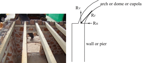
Eccentric application of vertical loads to masonry walls
-
(ii)
In the most frequent types of historic masonry (double or three-leaf masonry with loose connection between leaves), there is a more or less continuous vertical joint within the thickness of masonry (Fig. 8.5). The failure of those types of masonry in compression is characterized by the occurrence of vertical cracks on the faces of masonry, as well as within their thickness (Fig. 8.6), the latter being critical (Pina-Henriques et al. 2005; Oliveira et al. 2006), Vintzileou and Miltiadou (2008).
Fig. 8.5 
Surveyed types of historic masonries (Binda and Saisi 2001)
Fig. 8.6 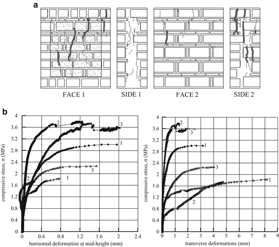
(a) Typical crack pattern for three-leaf masonry in compression, (b) opening of vertical cracks on the faces of masonry, as well as within its thickness as a function of compressive stresses (Vintzileou and Miltiadou 2008)


Actually, although the two families of cracks open at almost the same vertical load, the transverse ones grow faster. Thus, the failure of masonry is due to simultaneous compression and out-of-plane flexure of the leaves.
It should be noted that cracks within the thickness of masonry are not visible or detectable (unless significant out-of-plane deformation of masonry has occurred). Such cracks may be due to decay of materials, as well as to previous normal and seismic actions on the structure (Fig. 8.7). Therefore, instead of a solid masonry, separated leaves may be asked to resist vertical and horizontal actions. Needless to say that due to the separation between the leaves of masonry, (a) the real slenderness of the walls may be significantly increased, (b) the bearing capacity of walls both to compression and to out-of-plane bending are significantly reduced compared to the bearing capacity of solid walls.

Separation of the leaves of masonry walls during tests on the shaking table (Mouzakis et al. 2012a)
In conclusion, one could say that the estimation of the bearing capacity of masonry walls in compression has to be based on the real geometry, state and boundary conditions of the walls. For that purpose, the structural system has to be documented in terms of geometry, construction type of masonry and pathology.
8.2.3 The Case of Timber Reinforced Masonry
In earthquake prone areas around the globe (around the Mediterranean, in Asia, as well as in Latin America), systematic reinforcement of masonry is observed (Fig. 8.8). Although there is a vast variety of structural systems involving timber within masonry, there are clear signs testifying that those structural systems were developed with the purpose of resisting seismic actions (see e.g. Vintzileou 2011a).

Various types of timber reinforced structures in Europe (Source: https://www.google.gr/search?q=casa+pombalina+lisboa)
Although the contribution of the timber reinforcement to the compressive strength of masonry is the least significant aspect of those structural systems, test results (Vintzileou 2008) have shown that
-
(a)
Horizontal timber laces provide confinement to rubble stone masonry, thus, leading to a moderate enhancement (by 15–20 %) of its compressive strength. More importantly,
-
(b)
Timber laces lead to a significant enhancement of the deformation (vertical strain) masonry can sustain without being disintegrated (Fig. 8.9).
Fig. 8.9 
Compressive stress-vertical strain for masonry wallettes: Wallette 1-plain masonry, Wallettes 2 and 3-timber laced masonry (Vintzileou 2008)

8.3 Masonry Elements Subjected to In-Plane Shear
The behaviour of masonry elements under in-plane shear is of major significance for the seismic response of buildings, as documented by typical damage, i.e. diagonal or bi-diagonal cracks in walls and spandrels (Fig. 8.10). Thus, numerous research works were devoted to the behaviour of masonry under shear.

Severe damages to shear walls and spandrels (Onna, after the 2009 earthquake of L’Aquila, Italy)
In laboratory and in situ tests were carried out on wallettes subjected to diagonal compression, with the purpose of assessing the shear strength of masonry under zero normal stress. The results show strength values depending on the mechanical properties of materials, as well as on the bond between blocks and mortar. For example, Shahzada et al. (2012) have tested solid brick masonry wallettes in diagonal compression. The shear strength under zero normal stress was very low (the Authors do not even mention its value). On the other extreme, Ali et al. (2012) have tested several wallettes made of bricks and mortars (typical for Pakistan). The compressive strength of the mortar was varying between 3.0 and 27.0 MPa. For those, rather unusually strong mortars, they have measured shear strengths varying between 0.30 and 1.70 MPa. Brignola et al. (2006) report the results of in situ tests in several historic buildings in Tuscany. For the stone masonries tested by the authors, low shear strength values were obtained (varying between 0.04 and 0.067 MPa).
In situ diagonal compression tests on stone masonry walls by Chiostrini et al. (2000) yielded values of shear strength varying between 0.061 and 0.16 MPa. Corradi et al. (2003, 2008) have measured similar values of shear strength. Similar (low) values were measured in laboratory on wallettes made of three-leaf stone masonry to diagonal compression by Vintzileou and Tassios (1995)−0.15 MPa, as well as by Vintzileou and Miltiadou (2008)−0.10 MPa. The results obtained by Milosevic et al. (2012) on rubble stone masonry were quite scattered (between 0.024 and 0.313 MPa), irrespectively of the compressive strength of the mortar.
Limited in number test results are available for timber laced masonry (Vintzileou 2008). The presence of timber laces led to a shear strength under zero normal stress almost 5.0 times that of the plain three-leaf rubble stone masonry. More importantly, the strain at strength was by almost an order of magnitude larger.
However, the strength at zero normal stress is only one of the components of the bearing capacity of a masonry element subjected to in-plane shear, when failure is due to the occurrence of diagonal or bi-diagonal cracks. On the other hand, the in-plane behaviour of walls failing in bending or vulnerable to rocking needs to be investigated through testing under simultaneous in-plane shear and vertical load. Actually, several researchers have conducted tests on masonry walls under monotonic or cyclic shear (see i.a. Chiostrini et al. 2000; Corradi et al. 2003, 2008; Vasconcelos and Lourenco 2006; Costa et al. 2012a, b, c; Capozucca 2011; Silva et al. 2014).
Tests on individual structural members allow for the behaviour of full-scale elements to be investigated in detail (failure modes, deformations along three axes, failure load, ductility, etc.). Furthermore, the effect of various intervention techniques can be investigated. Tests on individual members provide data that are necessary for the development and the calibration of models to be applied for the assessment of the bearing capacity of existing elements, as well as for the design of the intervention techniques. It should be noted that due to the differences in materials, in geometry, in applied time-history, etc., it is impossible to provide a synthesis of the experimental results and to draw general conclusions. Finally, a large part of the tests on individual walls refer to modern brick and block masonry. Therefore, the experimental results on various construction types of historic masonry are still rather limited in number.
The available experimental data regard shear walls made of a variety of materials (mostly clay and concrete blocks, stones and mortar). Full scale walls or scaled models are tested. The walls are subject to simultaneous vertical load (either constant or varying during the lateral loading). The walls are either cantilevers or fixed at both ends. The aspect ratio (height to length) varies between 1:2 and 2:1. In some cases, there are also openings in the walls. The specimens are subjected either to monotonically increasing lateral load or to static cyclic lateral loading or (in a limited number of cases) to dynamic in-plane actions. The prevailing failure mode is due to the formation of diagonal or bi-diagonal cracks (Fig. 8.11), involving-in some cases-also compression failure close to the base of the wall (Silva et al. 2014). Flexural failure or mixed shear-flexural failure was observed for rather high aspect ratio values. Rocking was also observed in some cases (especially, under low vertical load, Silva et al. 2014). Typically, after the attainment of the maximum resisting shear force, significant force-response degradation is recorded (Fig. 8.12a). Deformations (vertical and horizontal) are recorded during testing. However, due to the differences among tested models, the author of this paper is unable to provide a comparison of the relevant experimental data. It should be noted that several researchers have worked on modeling of the behaviour of shear walls (see i.a. Vasconcelos and Lourenco 2006; Costa et al. 2012a; Magenes and Calvi 1997; Brencich and Lagomarsino 1998), developing either sophisticated models or simple ones, adequate for use by practitioners as well.

Typical shear failure of stone masonry walls under simultaneous vertical load (Vasconcelos and Lourenco 2009)

8.4 Masonry Elements Subjected to Out-of-Plane Bending
It is well known that in historic buildings subjected to seismic actions, the out-of-plane behaviour of (solid or with openings) walls may be critical (Fig. 8.13).

Typical damages due to out-of-plane seismic actions. (a) Typical vertical crack due to out-of-plane bending of the solid wall. (b) Typical vertical crack at mid-length of the wall and separation of walls at the corner of the building. (c) Out-of-plane collapse of wall. (d) Collapse of the corner of a building (due to combined in-and out-of-plane action)
The vulnerability to out-of-plane actions is due to typical characteristics of historic masonry buildings, namely, the flexible floor and roof diaphragms (Fig. 8.13b), as well as the defective connection between floors/roof and walls (allowing for significant out-of-plane deformations of walls), the defective connection of walls at building corners (Fig. 8.13a, c), the presence of openings close to the corners of the building and, last but not least, the frequent construction type of historic masonry (double- or three-leaf). Actually, the separation between leaves (due either to decay or to previous actions) leads to significant reduction of the out-of-plane stiffness of walls, whereas the masonry cross section is also significantly reduced (Fig. 8.13d) and Giuffrè et al. (1993).
It is obvious that the testing of individual walls out of their plane cannot describe the behaviour of walls belonging to a building. Furthermore, available test results are almost exclusively dealing with brick or concrete block masonry walls, whereas various testing procedures are applied. Some of the relevant publications are briefly presented herein: One of the earlier experimental campaigns was carried out at ABK (1981). Several construction types of masonry were tested, among them also multi-leaf brick masonry walls. The aim of this work was to assess the effectiveness of various intervention techniques, taking into account the slenderness ratio and the boundary conditions of the panels. 20 full-scale masonry panels were subjected to about 200 seismic inputs, covering the full range of USA seismicity. The walls were full height (floor to floor) and were not laterally supported along the vertical edges. The work provided data that were used both (a) to calibrate mathematical models developed by the authors for the prediction of the failure mode and (b) to draft guidelines for the design of various strengthening techniques. A finding to note is that the collapse mechanism was found to depend more on the induced peak velocities (at the top and the bottom of the panels) rather than on the relative deformation between the top and the bottom of the panels.
Griffith et al. 2004 investigated the response of unreinforced brick masonry wall panels subjected to out-of-plane loading. For this purpose, fourteen specimens, having different slenderness ratios (13.6 and 30.0), were constructed and tested. The test program included static, free-vibration, and dynamic tests (with induced harmonic, or impulse or seismic motions). However, the slenderness ratios of the walls are not typical for historic masonry. Simsir et al. (2004) carried out dynamic tests on four half-scale masonry walls made of lightweight concrete hollow blocks. The experimental set-up allowed testing walls in the free-standing boundary conditions as shown in Fig. 8.14. Two of the walls were tested in-plane, while the other two were subjected to out-of-plane seismic actions, (Fig. 8.14b). The aim of the experiment was to investigate the influence of the boundary conditions, namely the horizontal structures at top and constrains at the bottom of wall panels, simulating the real conditions of a wall panel. Differently from other similar tests, specimens did not exhibit a mid-height failure that leads to collapse, except for the cases where the panel was subjected to low axial load. Furthermore, it was proven that the flexibility of diaphragms can significantly enhance the out-of-plane displacements.

(a) Test set-up and (b) specimen at the shaking table (Simsir et al. 2004)
Tominaga and Nishimura (2008) have tested brick masonry walls out-of-their plane, by applying two concentrated loads at the thirds of the span. No vertical load was applied. Failure along mortar joints was observed. The maximum resistance was mobilized for very small deflection (of the order of few mm), but the residual resistance was significant, due to friction along the failed mortar joints.
Cavaleri et al. (2006) report the results of an experimental campaign on four (4) single leaf calcareous stone masonry walls (0.74 m long, 2.10 m high and 0.21 m thick). The walls were under constant compression load (equal to 0.12 the bearing capacity of walls to compression). Deformations were applied to the walls (by moving horizontally the base of the walls). The curvatures at the base region of the walls were also recorded. Failure was due to the occurrence of horizontal cracks along the mortar joints close to the base.
Meisl et al. (2006) have tested four multi-leaf plain masonry walls. The effect of the quality of construction (in terms of strength of mortar) and that of the soil conditions (one soft and one more firm substrate) were investigated. The results have shown little effect of the quality of construction on the overall behaviour of specimens. On the contrary, walls founded on soft soil exhibited more damages (for the same input) than those founded on firm soil.
Manoledaki et al. (2012) have tested piers made of three-leaf stone masonry. The piers were sitting on either a loose (Dr = 33 %) or a dense (Dr = 92 %) sand, through a rectangular RC footing (Fig. 8.15). The walls, either constrained or free at their top, were subjected to horizontal displacements at their mid-height.

Three-leaf stone masonry piers and experimental setup (Manoledaki et al. 2012)
The tests showed that the out-of-plane seismic performance of the masonry walls was substantially affected by soil–foundation–structure interaction (SFSI). As indicated by the two examined cases, soil resilience had a significant influence on system response. Foundation rocking resulted in a reduction of the soil–footing contact zone in the case of dense sand, whereas, in loose sand the response was governed by sinking (Fig. 8.16). The essential influence of the boundary conditions on the out-of-plane response of the walls is also amongst the key observations made from the tests. In the cases where the elongation of the wall was partially obstructed by the top support, the induced axial load led to significant enhancement of the out-of-plane capacity. The walls generally exhibited the typical cracking pattern associated with one-way vertical out-of-plane bending. Material crushing was restricted to the weak mortar joints.

Test results obtained by Manoledaki et al. (2012)
Recently, within the EU funded project NIKER, tests were carried out (Valluzzi et al. 2013) on three-leaf rubble stone masonry full scale panels (Fig. 8.17) subjected to out-of-plane excitations on a shaking table. The panels (1.30 m long, 2.60 m high and 0.50 m thick) were subjected to adequately scaled real accelerograms.

Test specimens and experimental setup (Valluzzi et al. 2013)
The panels failed under acceleration approximately equal to 0.30 g. As shown in Fig. 8.18, cracks typical for out-of-plane bending have occurred. Failure was due to the separation of the leaves of masonry and to the collapse of one of the two exterior leaves (Fig. 8.19).

Typical failure mode of three-leaf stone masonry walls subjected to out-of-plane seismic actions (Valluzzi et al. 2013)

Failure of walls 1 and 2 (Valluzzi et al. 2013)
The detailed data obtained during testing (accelerations, frequencies, displacements, etc.) allowed for full documentation of the behaviour of the panels. They have also served the purpose of prediction of the observed behaviour by means of modeling.
Tests on subassemblies (e.g. façade wall with portions of transverse walls) are also reported in the literature. Those tests are presented and commented upon in the following Sections.
8.5 Tests on Subassemblies and Building Models
8.5.1 Tests on Subassemblies
As shown in the previous Sections, tests on individual bearing elements (under monotonic or cyclic actions) provide valuable information regarding the failure mode under compression, shear or out-of-plane bending, as well as on properties like bearing capacity, deformability, hysteretic damping, stiffness, force-response degradation due to cycling, etc. Nevertheless, there are significant aspects of the seismic behaviour of masonry buildings that cannot be modelled and experimentally reproduced by testing individual bearing elements. Actually, the effect of the in-plane stiffness of floors and roofs, the effect of the connection between bearing walls, the behaviour of masonry elements subjected to simultaneous shear and out-of-plane bending, the capacity of masonry buildings to redistribute actions among bearing elements need to be identified through testing of subassemblies or models of entire buildings. Another important issue is the capacity of historic masonry buildings to undergo large post-elastic deformations, i.e. their ductility. Finally, the effect of several interventions applied with the purpose of improving the seismic behaviour of historic buildings, namely, the enhancement of diaphragm action of floors and roof, the improvement of the connection of walls by means of ties, etc. can only be exhaustively investigated on specimens simulating at least part of the entire building.
In the Literature, there are results obtained from quasi-static or dynamic tests on subassemblies. Some of them are related to the study of specific monuments (e.g. Pinto et al. 1999a, b, c, 2001). The valuable results of those tests are hardly offered to generalization. Therefore, they are not presented herein. There are also tests on subassemblies investigating the behaviour of arches and vaults (see i.a. Baratta and Corbi 2007; Taranu et al. 2010; Mouzakis et al. 2012b). Those experimental works are presented neither.
Al Shawa et al. (2009) have tested full scale subassemblies made of tuff masonry (Fig. 8.20), with the purpose of investigating the out-of-plane behaviour of walls connected with transverse walls. The research includes subassemblies before and after strengthening. The tested wall (3.40 m high, 0.25 m thick) was either free standing or connected to the transverse ones along a mortar joint. A third case was also considered, in which the walls were connected through bonding of stones, as well as through steel bars. The subassemblies were subjected to forced vibrations, following adequately scaled accelerograms of real earthquakes. The tests have proven the major significance of the connection between walls. Actually, in terms of maximum acceleration sustained before failure (or collapse), the free standing wall, as well as that connected to the transverse ones through a mortar joint, were able to sustain an acceleration approximately equal to 0.30 g. On the contrary, the proper connection between the walls, allowed for a peak ground acceleration equal to 0.60 g to be sustained.

Photo of a specimen after the test: case of out-of-plane loaded wall connected to the transversal walls through a mortar joint (Al Shawa et al. 2009)
The mechanisms of out-of-plane failure of a wall connected with transverse ones was studied by Restrepo-Vélez (2004) and Restrepo-Vélez and Magenes (2004) through testing of subassemblies made of dry stack masonry (Fig. 8.21). The models (scale 1:5) allowed for identification of the two possible failure modes, i.e. detachment of the out-of-plane loaded wall from the transverse ones and out-of-plane collapse of the wall.

The same mechanisms were detected also by Bui et al. (2010). The subassemblies they have tested were subjected to monotonically increasing uniformly distributed load on the longitudinal wall (Fig. 8.22).

Test setup and failure mode of walls with flanges (Bui et al. 2010)
A full scale shaking table test on a 3-D specimen made of three-leaf masonry was performed by Costa et al. (2012a). The subassembly-simulating a typical façade of historic buildings in the Azores-exhibited the same failure mechanisms, together with detachment of the leaves of masonry (Fig. 8.23).

Failure mode of subassembly (Costa et al. 2012a)
Costa et al. (2012b) carried out an in situ test on a building severely damaged during the Azores earthquake in 1998 (Fig. 8.24). The building was made of double leaf stone masonry.

Testing arrangement and instrumentation of a building tested on situ (Costa et al. 2012b)
Cyclic tests were performed, not to collapse though due to the limitations of the equipment, as well as for safety reasons. Valuable data were collected regarding the dynamic properties of the structure, the sustained deformations, hysteretic behaviour, etc. The behaviour of the structure was tested also after the application of reinforced plaster on the walls.
A 3D subassembly was tested within the EU funded project NIKER (Vintzileou et al. 2012a, b). The subassembly (made of three-leaf stone masonry) consists in one wall with a portion of a transverse wall at its mid-length and a parallel wall of rectangular section (Fig. 8.25). A timber floor (typical for historic buildings) is provided. For dynamic similitude purposes, additional masses are fixed on the floor before testing on the earthquake simulator. The subassembly was subjected to a series of adequately scaled accelerograms of the Irpinia, Italy 1980 earthquake out-of-the plane of the parallel walls. Figure 8.26 shows the crack pattern (at PGA ~ 0.50 g). The effect of the portion of the transverse wall (failed in shear) on the longitudinal wall to which it is connected is shown. Furthermore, the flexible wall of rectangular section was not severely damaged. It exhibited, however, extensive detachment of the masonry leaves. It should be noted that the same subassembly after strengthening (grouting of masonry, enhancement of the diaphragm action of the floor and connection thereof with the walls) exhibited a clear rocking behaviour.

The specimen and its construction details (Vintzileou et al. 2012)

Crack pattern of the subassembly (Vintzileou et al. 2012)
The experimental works briefly presented herein have provided valuable information on several aspects of the out-of-plane behaviour of masonry walls under realistic boundary conditions. It should be noted, however, that in most of the laboratory tests there was no vertical load on the out-of-plane loaded walls. Similarly, with one exception, there was no diaphragm at floor(s) levels. The presence of vertical load plays a positive role on the out-of-plane behaviour of walls, whereas the effect of a more or less flexible diaphragm may affect significantly the seismic behaviour of the structure. Nevertheless, the obtained results are valuable and, in the opinion of the author of this paper, there is a need for systematic analytical work (with simulation of the test specimens), for the international community to take the maximum possible profit of the experimental data.
8.5.2 Tests on Building Models
Testing models of entire buildings (either under monotonic or under seismic actions) has the advantage of simulating parameters that cannot be simulated through testing of subassemblies or individual bearing elements. This is of major significance, due to some typical characteristics of existing masonry buildings that govern their seismic behaviour, namely, the presence of more or less flexible floors and roofs (that allow the vertical elements to deform independently from one another), the connection between horizontal and vertical elements, as well as the connection between longitudinal and transverse walls (its quality affecting significantly the box action of the building and, hence, the magnitude of the imposed deformations). Furthermore, basic parameters like dynamic properties (and their modifications during the seismic event), hysteretic properties and overall ductility cannot be realistically assessed unless the entire structure is considered. It is mentioned, as an example, that it is typically assumed that unreinfrorced masonry buildings are very brittle. However, inspection after seismic events shows that many structures survive (damaged, of course) in contradiction with our calculations. Last but not least, the efficiency of several intervention techniques cannot be assessed on the basis of tests on individual members. Actually, those techniques that aim at improving the overall behaviour of buildings (e.g. enhancement of the diaphragm action of floors or the arrangement of ties to improve the connection between walls) need to be assessed on the basis of large scale tests. In recognition of the above advantages of testing building models, several researchers have performed tests either on shaking tables or quasi-static tests on building models.
It should be noted, however, that the interpretation of the results obtained from testing building models is not as self evident as one could possibly think. Actually, due to several constraints related to this type of tests, very careful design of testing campaign is needed, along with systematic analytical work on both prototypes and models. In fact, shaking table tests are quite expensive (in terms of construction, instrumentation, use of the facility, etc.). Thus, within each testing campaign, the number of models that are tested is limited. By way of consequence, several parameters are usually simultaneously modeled and, hence, frequently, it is not possible to directly assess the effect of each of them. On the other hand, in order to take the maximum profit out of those tests, building models are subject to series of input motions (of increasing magnitude). Thus, the behaviour of the model subjected to a series of seismic inputs may be different than the behaviour to be exhibited by a model directly subjected to high intensity actions.
In shaking table tests, there are also limitations related to the capacity of the facility (in terms of plan dimensions, degrees of freedom, total height of the model coupled with total weight, maximum acceleration and maximum displacement that can be imposed to the model). Those limitations lead to either small scale models or to testing of rather simple in configuration buildings. In the first case, there are scale effects (to be taken into account when assessing the experimental results), the detailed discussion on which is beyond the scope of this paper. Furthermore, for dynamic similitude reasons, additional masses need to be arranged. The fact that those masses are inevitably located on floors and roof (instead of being distributed along the height of the model), as well as the fact that additional masses are transferred to part of the cross section of masonry (e.g. through the timber beams of floors resting on the interior leaf of a double- or three-leaf masonry) may affect the behaviour exhibited by the model. Last but not least, the foundation of the model cannot be realistically modeled (the models are fixed on a rigid base) and, hence, also soil structure interaction cannot be studied.
In this Section, a brief presentation of the results obtained from tests on building models in the last three decades is attempted. The overview of the experimental data is limited to tests on historic masonry. Still, an exhaustive presentation of all the available data being impossible, selected works are presented, those that allow for the identification of the effect of major features on the seismic behaviour of historic buildings. Although this paper does not cover the effect of intervention techniques to historic buildings, some selected results are included herein. Those results concern the effect of some techniques that could be termed as “systemic” interventions, in the sense that they affect the overall behaviour of historic buildings (e.g. enhancement of diaphragm action of floors and roofs, improvement of connection among the walls, etc.).
8.5.2.1 Short Presentation of Tested Models
The models that were subjected either to pseudo-dynamic or to dynamic tests on a shaking table have quite different characteristics in terms of scale (1:1 to 1:10), in dimensions, in number of storeys (1, 2 or 4), in arrangement of openings (doors and windows), in the flexibility of floors and roofs, in materials and construction type of masonry, etc. Therefore, a direct comparison of the experimental results is not possible. Nevertheless, a qualitative comparison of the data is attempted wherever possible.
Benedetti (1980) performed a series of pseudo-dynamic tests on scale 1:2, one-storey multi-leaf stone masonry model buildings (plan dimensions 1.90 × 2.20 m, Fig. 8.27a). Seismic excitation was simulated by static lateral loads via actuators. No roof was provided to the models. Three of the models were tested unstrengthened, whereas two models were tested after the application of a cement grout. One model was fully grouted, the other was partially grouted.


An overview of building models subjected to dynamic testing. (a) Benedetti (1980). (b) Tomaževič et al. (1990, 1991, 1993). (c) Spence and Coburn (1987, 1992). (d) Models tested at ISMES and at LEE/Athens (Benedetti et al. 1998). (e) Bayülke et al. (2000). (f) Juhásová et al. (2002). (g) Juhásová et al. (2008). (h) Bergamo et al. (2006). (i) Tomaževič et al. (2009). (j) Ersubasi and Korkmaz (2010). (k) Shashi and Pankaj (2000). (l) Meguro et al. (2012). (m) Ahmad et al. (2010, 2012). (n) Mendes and Lourenco (2010). (o) Magenes et al. (2010, 2012a, b). (p) Mazzon et al. (2009). (q) Mouzakis et al. (2012a) and Adami et al. (2012)
Tomaževič et al. (1990, 1991, 1993) report the results of two series of shaking table tests on reduced scale (1:4) stone masonry building models. The two-storey models (Fig. 8.27b) were 1.0 × 1.10 m in plan. The total height was equal to 1.50 m, whereas the thickness of walls was equal to 0.12 m. The models were subjected along one direction, parallel to the walls without openings, to an adequately scaled acceleration record (Montenegro 1979 earthquake). The purpose of the research was to investigate the effect of the rigidity of floors. Thus, Model A was provided with timber floors (simply resting on the walls without openings), Model B was provided with RC slabs, whereas in Model C, prestressed steel ties (located underneath the timber beams) were used to improve the connection between longitudinal and transverse walls and to connect the floors to the walls. Finally, in Model D, the ground storey floor was a brick vault, whereas a timber floor was provided to the upper storey (Fig. 8.27b). Poor quality materials, typical for old buildings were used for the construction of the models.
Spence and Coburn (1987, 1992) conducted an experimental program on three full scale single storey masonry building models, simulating the structural system that is typical for Eastern Turkey. The models, subjected to uni-directional impulse tests were 4.50 × 4.50 m in plan, 2.60 m high, whereas the (rubble stone masonry) walls were 0.60 m thick. All models were provided with a typical timber roof (made of timber beams and timber planking). On top of the planking a layer of 0.20 m thick compacted soil was added. Some characteristics of the models are shown in Fig. 8.27c. The models were subjected to gradually increasing impulse load until failure.
The most extensive experimental programme reported in the literature is the one carried out at ISMES (Italy) and NTUA (Greece). Fourteen two-storey models (before and after interventions) at scale 1:2 were tested (Benedetti et al. 1998). Eight models were tested at ISMES (4 brick masonry and 4 stone masonry), and six models were tested at the Laboratory of Earthquake Engineering, Athens (3 brick masonry and 3 stone masonry) (Fig. 8.27d). The lintels were either arched or horizontal beams. All models were provided with timber floors and planking. In general, poor quality mortar was used. In the models tested at ISMES, the connection between orthogonal walls was rather defective. The models were subjected to scaled accelerograms along two orthogonal axes before and after the application of interventions. Unfortunately, the investigated parameters are so many (in terms of applied interventions) and interrelated that it is rather hard to detect the effect of each separate remedial measure.
One building model was tested on a unidirectional impulse table by Bayülke et al. (2000). The model made of pumiced bimsblock masonry was single storey. It was 4.00 × 5.00 m in plan, 2.60 m high. Masonry walls were 0.20 m thick. A peculiar characteristic was that the compressive strength of the blocks was significantly smaller than the compressive strength of the mortar. A concrete slab was constructed at the top of the model. The model employed a concrete slab (made with ready mix concrete) and timber tie beams at roof level (Fig. 8.27e).
Juhásová et al. (2002) conducted a series of shaking table tests at ISMES (Bergamo). Two-storey, scale 1:2, brick masonry models were tested before and after interventions. The peculiarity of those models is that they have quite pronounced asymmetry. Some of the characteristics of the model are shown in Fig. 8.27f. The model was initially tested as built until severely damaged. Then, it was retrofitted using lime cement fibre plaster reinforced with plastic grids.
Juhásová et al. (2008) carried out shaking table tests on a full scale single storey stone masonry building (Fig. 8.27g) at LNEC in Lisbon. The asymmetrical model (non-provided with roof) was 3.58 m wide, 4.01 m long, 3.60 m high. The thickness of walls was equal to 0.24 m. The model was subject to the adequately scaled accelerogram of the Montenegro earthquake.
Bergamo et al. (2006) carried out shaking table tests on a 2-storey tuff masonry model building with three-leaf walls (Fig. 8.27h), before and after retrofit, at the facilities of CESI in Bergamo. The model was built in reduced scale of 1:2, and was 2.85 m long, 2.60 m wide and 3.30 m high. The walls (0.30 m thick) were three-leaf (exterior leaves 0.10 m thick, filling with small pieces of tuff and mortar). The two exterior leaves were connected with header stones. Timber floors with plywood pavement were provided at both floor levels. Concrete tie beams were constructed at both floor levels. Timber lintels were provided to the openings. The model was tested both as-built and after strengthening using GFRP strips. The model was subjected to adequately scaled real accelerogram along two orthogonal axes.
Tomaževič et al. (2009) have tested five two-storey brick masonry building models on the shaking table. The models (scale 1:4), with timber floors (Fig. 8.27i) were tested before and after strengthening using CFRP laminates. Seismic isolation was also considered in some cases. The models were 1.32 m long, 0.76 m wide and 1.71 m high. The walls were 0.063 m thick. The 1979 Montenegro earthquake accelerogram was imposed along x, y and z axes.
Ersubasi and Korkmaz (2010) have tested ten small scale models (scale 1:10) on a shaking table (Fig. 8.27j). The dimensions of the single storey models were quite small (0.35 m long, 0.26 m wide and 0.30 m high). A marble plate, positioned at the top of the models was simulating a RC slab. One model was tested as-built. The other nine models were tested strengthened using various intervention techniques. Constant amplitude sinusoidal displacement was applied during tests and the frequency (and acceleration) of the motion were gradually increased.
Shashi and Pankaj (2000) have tested (on an impulse table) two full scale models of single storey stone masonry (Fig. 8.27k). The models were first tested strengthened using various techniques. Then, they were repaired and retested. The models were 2.90 m long and 2.60 m wide. The roof is described as “gable type” without any further information. The quality of materials and the construction type of masonry are not given in the publication.
Meguro et al. (2012) conducted an experimental research on two scaled (1:4) single storey models with timber roof (Fig. 8.27l). The models (0.95 m long, 0.95 m wide and 0.72 m high) having walls 0.10 m thick made of stone masonry were subjected to unidirectional motions. The models were tested both as-built and retrofitted after damage.
Ahmad et al. (2010, 2012) performed a series of tests on one single storey stone masonry model with a reinforced concrete slab, simulating typical rural buildings in Pakistan (Fig. 8.27m). The model (1.52 m long, 1.22 m wide and 1.04 m high) made of double-leaf masonry, it was scaled to 1:3 and it was subjected to a series of motions along its weak direction.
Mendes and Lourenco (2010) have tested two 4-storey models at the LNEC facility (Fig. 8.27n). The models were subjected to artificial accelerograms along two orthogonal directions. One of them was tested as-built, the other after interventions. The two models, typical for houses in Lisbon, were at 1:3 scale. The models (4.8 m long, 3.15 m wide and 4.8 m high) were made of single leaf stone masonry 0.17 m thick and timber floors (timber beams and MDF panels as pavement). The panels of the pavement were positioned leaving 1 mm joints among them, in order to reduce the in-plane stiffness of the diaphragms. The intervention techniques that were applied, aimed at increasing the diaphragm action of the floors and at improving the connection between floors and walls (to prevent out-of-plane collapse of the latter).
Magenes et al. (2010, 2012a, b) report the results of a series of shaking table tests on full scale stone masonry models carried out at the Eucentre facility, Pavia. The three models were 2-storey buildings with timber floor and roof (Fig. 8.27o). They were made of double-leaf stone masonry, 0.32 m thick. The models (provided with additional masses for dynamic similitude reasons and adequately instrumented) were subjected to series of scaled accelerograms (1979 Montenegro earthquake). One of the models was tested as built, the others after the application of intervention techniques (such as enhancement of the diaphragm action by means of a second planking, improvement of the connection of horizontal and vertical members, substitution of the floor by a reinforced concrete slab etc.).
Mazzon et al. (2009) and Mazzon (2010) report the results of shaking table tests on two storey three-leaf stone masonry building models (scale 2:3). The models (Fig. 8.27p) were provided with timber floors with double planking (for improved diaphragm action). One of the models was tested before the application of grouting to masonries, it was grouted and retested, whereas the second model was tested grouted. The purpose of those tests, with models subjected to a series of motions along two orthogonal axes, was among others, to detect the effect of grouting on the dynamic properties of buildings. Finally,
Two two-storey building models were tested at the facility of the Laboratory of Earthquake Engineering, Athens. The models, made of three-leaf rubble stone masonry (Mouzakis et al. 2012a and Adami et al. 2012), were identical in geometry, materials, construction details, etc. Their only difference was that one was made of plain masonry, whereas the other was provided with timber-laces, to simulate structural systems that are very common in earthquake prone areas around the Mediterranean. The two models (Fig. 8.27q) were subjected to a series of scaled accelerograms (Kalamata, Greece, 1986 and Irpinia, Italy, 1980) along two orthogonal axes, until they are severely damaged. Subsequently, they were strengthened (enhancement of diaphragm action and grouting of masonry) and retested to failure.
The short presentation of the Literature related to dynamic testing of building models shows the variety of the parameters investigated by various researchers and, hence, the difficulties in making comparisons and draw general conclusions. However, an attempt for such a comparison is presented herein, together with an effort to draw qualitative conclusions that may be of interest for the Reader of this paper.
8.5.2.2 The Overall Behaviour of Building Models at Their as-Built State
Although, as depicted in the previous paragraph and in Fig. 8.27, there were significant differences between the models tested by various researchers (in terms of scale, materials, construction type of masonry, number of storeys, loading history, etc.), Fig. 8.28 shows the similar results obtained by almost all experimental campaigns in terms of failure mode of the models tested on a shaking table. Actually, the models shown in the photographs and sketches of Fig. 8.28 have common characteristics, typical for historic buildings, namely, rather flexible in their plane diaphragms, a more or less good connection between perimeter walls at the corners of the building, small to medium size openings (windows and doors) and piers of rather small aspect ratio. Thus, the experimental results reproduce the damages that are usually observed to masonry buildings after seismic events, i.e.: (a) Diagonal or bi-diagonal cracks in walls subjected to in-plane shear, (b) Diagonal or bi-diagonal cracks to the masonry plates between openings of the two storeys (very vulnerable to shear, as they are usually under simultaneous horizontal tension), (c) Cracks attributed to the out-of-plane or in-plane bending of walls, i.e. almost vertical cracks close to the corners of the buildings and horizontal cracks at top and bottom of piers. In some cases, when openings are located close to the corners of a building, partial or total collapse of that region is observed. Finally, (d) in case of three-leaf masonry, separation between leaves and partial collapse of the exterior leaf of masonry was observed.

Overview of the general behaviour of building models. (a) Benedetti 1980. (b) Tomaževič et al. 1990, 1991, 1993. (c) Spence and Coburn 1987, 1992. (d) Benedetti et al. 1998. (e) Bayülke et al. (2001). (f) Tomaževič et al. 2009. (f) Tomaževič et al. 2009. (g) Shashi and Pankaj 2000. (h) Meguro et al. (2012). (i) Mendes and Lourenco (2010). (j) Magenes et al. (2010, 2012a, b). (k) Mazzon et al. (2009). (l) Mouzakis et al. (2012a) and Adami et al. (2012). (m) Adami et al. (2012)
It should also be noted that in the model tested by Adami et al. (2012), in which masonry was provided with horizontal timber laces, significant improvement of the behaviour was observed. Actually, the damages occurred to the timber laced model due to a seismic motion by 30 % higher (in terms of PGA) than in the unreinforced masonry model were significantly lighter (in terms of width of cracks), whereas separation between the leaves of masonry was practically prevented. Figure 8.28m shows a splice of longitudinal timber elements, as well as the timber laces at one corner of the building: The relative movement of the timber elements at their connections proves that the timber laces were mobilized and they have prevented the opening of wide cracks in masonry. Furthermore, the presence of timber laces has reduced the out-of-plane vulnerability of walls. As shown in Fig. 8.29, the displacements of the long walls of the timber laced model were almost equal to those of the unreinforced masonry model subjected to 30 % smaller PGA.

More detailed direct evaluation of the experimental results reported in the literature would require the availability of measured data, as well as systematic analytical work. Such an assessment is obviously beyond the scope of this paper. However, the fact that most of the testing campaigns reproduce the real behaviour of historic buildings subjected to seismic actions is a clear indication of the reliability of the obtained data. Thus, it can also be assumed that testing building models on a shaking table may provide reliable results on the effect of various intervention techniques. Although the study of the effect of repair and strengthening techniques on the seismic behaviour of historic buildings is out of the scope of this paper, the author would like to comment on selected experimental results that demonstrate the effect of two intervention techniques frequently applied to historic buildings and widely accepted also by Architects involved in the preservation of the built cultural heritage, namely grouting of masonry and enhancement of the diaphragm action of floors and roofs.
8.5.2.3 The Effect of Grouting and of Enhancement of the Diaphragm Action on the Behaviour of Historic Buildings
Due to the fact that masonry is a brittle material and, by way of consequence, masonry elements reach their maximum resistance at rather small imposed deformation, it is desirable to ensure to masonry buildings sufficient box-action. In such a case, the deformations to be sustained by the building are significantly reduced (for the same seismic input) and the building can sustain even strong motions without collapse. Along the same line, vulnerable construction types of masonry (double- and three-leaf masonries) that become “monolithic” through interventions, can sustain seismic actions without significant separation of their leaves and, hence, without local or more generalized collapse of the exterior leaf. Among the techniques available for enhancing the box action of masonry buildings and making the masonry behave in a more or less monolithic way, this section focuses on the enhancement of the diaphragm action of floors and roofs, as well as on the grouting of masonry.
In the past decades, the replacement of timber floors and roofs by RC (horizontal or inclined) slabs was quite frequent. However, in addition to the fact that such a replacement is rather invasive (as it alters significantly the original structural system), there is evidence of catastrophic effects of this intervention. Actually, when-stiff in their plane and quite heavy-RC slabs are simply supported by masonry (in many cases, not strengthened), they may act as a hammer during the earthquake, thus causing non-repairable damages to masonry (Fig. 8.30). Thus, the possibility to ensure sufficiently stiff diaphragms without replacing the original timber floors and roofs was experimentally investigated by several researchers.

Catastrophic effect of RC slabs on poor quality (unstrengthened) masonry (courtesy of Prof. C.Modena)
Piazza et al. (2008), Valluzzi et al. (2010), Wilson et al. (2011), Zaopo (2011) have tested timber diaphragms either as-built or stiffened using various techniques (e.g. double board, FRP strips, diagonal steel ties, plywood panels, RC slab, etc.). They have tested single span diaphragms in their plane (monotonically or cyclically) and they have recorded both the deflection of the diaphragm and the respective in-plane load. As shown in Fig. 8.31, the use of double board may lead to an increase of the in-plane stiffness of the floor, almost by an order of magnitude. The use of plywood as pavement provides similar stiffness with a reinforced concrete slab. Similar results are shown in Fig. 8.32, where the lower curves correspond to floors typical for historic buildings. It is evident that, in all cases, significant enhancement of the in-plane bearing capacity of the floors was also recorded. On the basis of the available results, one may conclude that the addition of a second layer of boards (preferably, at an angle with respect to the original layer of boards) may render the diaphragms sufficiently stiff in their plane. This is a very promising result, since this technique is reversible and acceptable even for high value historic structures.

Experimental setup and main results (Piazza et al. 2008)

The effect of the enhanced in-plane stiffness of diaphragms was also tested through shaking table tests of entire building models. Actually, Tomaževič et al. (1991, 1993) have tested four building models with four different types of floors (model A: typical timber floor, model B: RC slab, model C: timber floor with prestressed steel ties, model 4: vaulted floor, see also Fig. 8.27b). As shown in Fig. 8.33, the typical timber floor is rather flexible in its plane. Actually, the mid-span displacement is almost double the displacement at the supports of the floor. On the contrary, in the other three models, the floors did perform quite satisfactorily, thus forcing the supporting walls to sustain practically equal displacements. The results were similar in the case of the building models tested by Magenes et al. (2010, 2012a, b). The authors did also draw a very significant conclusion by stating that “…the improvement on the seismic performance appears to be related more to the improvement of the floor-to-wall and roof-to-wall connections, rather than to a strong in-plane stiffening of the diaphragms”.

Mouzakis et al. (2012a) in their shaking table tests have provided to the building models a second layer of boards (at an angle of 45° with respect to the original pavement, Fig. 8.34). Natural frequency measurements along x and y axes have shown a significant difference along the two axes (6.05 and 4.21 Hz respectively), due to the significantly smaller stiffness perpendicular to the long side of the model.

Enhancement of the diaphragm action of floors (Mouzakis et al. 2012a): (a) the original pavement, (b) the pavement with the second layer of boards, (c) detail of the connection between diaphragm and walls, (d) the model after strengthening
After strengthening, the two values were substantially larger (10.36 and 9.95 Hz respectively) indicating a significant overall increase of the stiffness of the model. More importantly, the two frequency values are almost equal along the two axes, indicating that the stiffness of the strengthened diaphragms was able to ensure the box action of the model.
The effect of grouting on the seismic behaviour of building models was investigated by several researchers, in most cases combined with other intervention techniques as well. Mazzon et al. (2009) and Mazzon (2010) have investigated the effect of grouting alone. One of the main findings of their research is that grouting provides a significant enhancement of the seismic resistance of masonry buildings without altering their dynamic properties. Grouting prevents the separation of masonry leaves and, hence, it reduces their seismic vulnerability.
Tests by Adami et al. (2012) on a timber laced masonry model before and after the application of grouting have shown that under the same input motion that led to significant damages of the unstrengthened model, the grouted model did not suffer any damage.
A final observation that, in the opinion of the author, needs to be further investigated and discussed upon is illustrated in Fig. 8.35. Shaking table tests by Mouzakis et al. (2012a) have shown that, although masonry is a brittle material and masonry elements are also brittle, masonry buildings may exhibit significant ductility, even at their as-built state. Although this result is reported with caution and it definitely needs to be confirmed by further experimental data, it may insinuate that historic masonry buildings avail of reserves-not easily detectable by calculations-which ensure a significantly better behaviour than usually assumed. It should be noted that this observation seems not to contradict reality, as many historic structures survived several earthquakes, although according to our calculations they should have failed.

Envelop of hysteresis loops for a plain masonry building model tested on the shaking table before and after strengthening (Mouzakis et al. 2012a)
8.6 Concluding Remarks
This paper provides an overview of the results obtained from testing masonry elements, subassemblies and building models. Although this overview is clearly incomplete, both because it does not cover but a part of the available experimental results and because it does not offer but some general comments on the data, it allows for some qualitative conclusions to be drawn:
-
(a)
The international Literature is rich in results of experimental campaigns related to the behaviour of masonry elements (in compression, shear or out-of-plane flexure), of subassemblies, as well as of models of entire buildings. A vast variety of combinations of building materials, construction types of masonry, geometry of specimens, experimental setups, types of loading, scale of tested specimens, etc. can be found in publications. Valuable data are available on the mechanical properties of various types of masonry, as well as on stiffness and bearing capacity of elements, on the hysteretic behaviour of elements or assemblies. However,
-
(b)
Due to the variety of parameters investigated by various researchers, a direct comparison among seemingly comparable experimental results is in many cases not possible. In order to take the maximum profit of the available valuable data, the development of sound physical models is necessary. Furthermore, systematic analytical work is needed, in order to validate and calibrate physical models and propose design models adequate for practical use.
-
(c)
Although numerous experimental campaigns were carried out throughout the globe, there are still several aspects of the behaviour of historic masonry structures that remain insufficiently investigated. For example, out of the frequent types of masonry found in historic structures, only a limited variety has been investigated to date. Even their behaviour under compression is not adequately documented (in terms of strength, deformability, post-peak behaviour, etc.). Furthermore, the behaviour of historic masonry under a combination of in- and out-of-plane actions is not sufficiently investigated at the level of structural member or subassemblies. Taking into account the vulnerability of historic masonry to out-of-plane actions and the subsequent effect of that vulnerability to the in-plane behaviour of structural members, this lacuna is quite significant. Moreover,
-
(d)
The experimental results are not presented in a form that would allow for comparisons at a large scale. Even the definition of some terms differs from publication to publication. Thus, although valuable qualitative conclusions can be drawn, the need for results liable to quantitative assessment is-in general-not satisfied. If one adds to those difficulties the inherent scatter of the experimental results, it becomes obvious that an exhaustive assessment of the Literature is a task with rather dubious outcome.
-
(e)
Thus, the author of this paper would like to make a proposal for future work within the European Association: An international group of experts both in experimental work and in the preservation of the built cultural heritage could collect all relevant publications. The group could establish a model for the presentation of experimental data, rendering the data liable to quantitative evaluation. The model forms should be filled for each publication. Obviously, in many cases it would be necessary for the group to contact the researchers asking for more data or for data in the adequate form. The final step would be the assessment of the experimental results and the creation of a database that could be made available to the Public. Such a database could also allow for the identification of open issues and, thus, guide further research on the subject. The author of this paper is conscious of the fact that such an operation is quite ambitious. However, it is strongly believed that this is a necessary step for the rationalization of the work of Engineers and, hence, for the preservation of the wealth the built cultural heritage constitutes for Europe.
References
ABK (1981) Methodology for mitigation of seismic hazards in existing unreinforced masonry buildings: wall testing, Out-of-plane. ABK Topical Report 04. Technical report, ABK, California, USA
Adami CE, Vintzileou E, Mouzakis C, Karapitta L (2012) Three-leaf stone masonry models with timber ties: the effect of timber ties and strengthening techniques on seismic response. SAHC 2012, Wroclaw (electronic source)
Ahmad N, Ali Q, Crowley H, Pinho R (2010) Displacement-based seismic risk assessment of stone masonry buildings of Pakistan. In: 3rd Asia conference on earthquake engineering Bangkok, Thailand (electronic source)
Al Shawa O, Benedetti S, Bellisario M, de Felice G, Mauro A, Paolacci F, Ranieri N, Roselli I, Sorrentino L (2009) Prove sperimentali su tavola vibrante di pareti murarie sollecitate fuori dal piano. ReLUIS final deliverable, Annex PF-1.2-UR09_15 (in Italy)
Ali Q, Badrashi YI, Ahmad N, Alam B, Rehman S, Banori FAS (2012) Experimental investigation on the characterization of solid brick masonry for lateral shear strength evaluation. Int J Earth Sci Eng 4(4):782–791
Baratta A, Corbi O (2007) Stress analysis of masonry vaults and static efficacy of FRP repairs. Int J Solids Struct 44:8028–8056
Bayülke N, Gençer O, Başyiğit C, Terzi S (2000) Impulse table test of a “bimsblock” masonry structure. In: International conference on the seismic performance of traditional buildings, Istanbul, Turkey
Benedetti D (1980) Repairing and strengthening stone masonry buildings. In: International research conference on earthquake engineering. Skopje, pp 503–515
Benedetti D, Carydis P, Pezzoli P (1998) Shaking table tests on 24 simple masonry buildings. J Earthq Eng Struct Dyn 27(1):67–90
Bergamo G, Eusebio M, Manfredi G, Prota A (2006) Shake table tests on a tuff masonry building. In: VIII U.S. National conference on earthquake engineering, San Fransisco, California, USA
Binda L (ed) (2008) Learning from failure-Long-term behaviour of heavy masonry structures. WIT Press, Southampton, p 228
Binda L, Saisi A (2001) State of the art of research on historic structures in Italy. Department of Structural Engineering, Politecnico of Milan, Milano
Binda L, Baronio G, Mirabella Roberti G, Penazzi D (1999) Caratteristiche morfologiche e meccaniche di alcune murature di Catania. L’ingegneria sismica in Italia, 9° Convegno Nazionale Torino. Electronic source (in Italian)
Brencich A, Lagomarsino S (1998) A macroelement dynamic model for masonry walls. In: Pande GN, Middeton J, Kralj B (eds) Computer methods in structural masonry 4: fourth international symposium. E&FN SPON, Routledge
Brignola A, Podesta S, Lagomarsino S (2006) Experimental results of shear strength and stiffness of existing masonry walls. In: Roca P, Modena C, Agrawal S (eds) Structural analysis of historical constructions-lourenco. Taylor and Francis Group, London (electronic source)
Bui TT, Limam A, Bertrand D, Ferrier D, Brun M (2010). Masonry walls submitted to out-of-plane loading: experimental and numerical study. In: Proceedings of 8th international masonry conference, Dresden (electronic source)
Capozucca R (2011) Shear behaviour of historic masonry made of clay bricks. Open Constr Build Technol J 5(Suppl 1-M6):89–96
Cavaleri L, Fossetti M, La Mendola L, Papia M (2006) Roca P, Modena C, Agrawal S (eds) Structural analysis of historical constructions-lourenco. Taylor and Francis Group, London (electronic source)
CEN-EN1996-1-1 (2005) Design of masonry structures-General rules for reinforced and unreinforced masonry structures, Brussels, 123pp.
Chiostrini S, Galano L, Vignoli A (2000) On the determination of strength of ancient masonry walls via experimental tests. In: 12th WCEE, Auckland, New Zealand (electronic source)
Corradi M, Borri A, Vignoli A (2003) Experimental study on the determination of strength of masonry walls. In: Construction and building materials, vol 17. Elsevier, pp 325–337
Corradi M, Tedeschi C, Binda L, Borri A (2008) Experimental evaluation of shear and compression strength of masonry wall before and after reinforcement: deep rejointing. In: Construction and building materials, vol 22. Elsevier, pp 463–472
Costa AA, Arede A, Costa A, Guedes J, Silva B (2012a) Experimental testing, numerical modelling and seismic strengthening of traditional stone masonry: comprehensive study of a real Azorian pier. Bull Earthq Eng 10:135–159
Costa AA, Arede A, Costa A, Oliveira CS (2012b) Out-of-plane behaviour of existing stone masonry buildings: experimental evaluation. Bull Earthq Eng 10:93–111
Costa AA, Arede A, Costa AC, Penna A, Costa A (2012c) Out-of-plane shaking table test of a full scale stone masonry façade. In: 15th WCEE, Lisbon (electronic source)
Da Porto F, Valluzzi MR, Modena C (2003) Investigations for the knowledge of multi-leaf stone masonry walls. In: First international congress on construction history, Madrid, Spain, 20–24 January 2003, vol II. pp 713–722
Ersubasi F, Korkmaz H (2010) Shaking table tests on strengthening of masonry structures against earthquake hazard. J Nat Hazards Earth Syst Sci 10:1209–1220
Giuffrè A, Baggio C, Carocci C (1993) Sicurezza e conservazione dei centri storici. Laterza, Bari (In Italian)
Griffith MC, Lam NTK, Wilson JL, Doherty K (2004) Experimental investigation of unreinforced brick masonry walls in flexure. J Struct Eng 130(3):423–432
Juhásová E, Hurák M, Zembaty Z (2002) Assessment of seismic resistance of masonry structures including boundary conditions. J Soil Dyn Earthq Eng 22:1193–1197
Juhásová E, Sofronie R, Bairrão R (2008) Stone masonry in historical buildings – Ways to increase their resistance and durability. J Eng Struct 30:2194–2205
Magenes G, Calvi GM (1997) In-plane seismic response of brick masonry walls. Earthq Eng Struct Dyn 26:1091–112
Magenes G, Penna A, Galasco A (2010) A full-scale shaking table test on a two-storey stone masonry building. In: 14th ECEE, Beijing (electronic source)
Magenes G, Penna A, Rota M, Galasco A, Senaldi I (2012a) Shaking table test of a strengthened full scale stone masonry building with flexible diaphragms. In: 8th SAHC conference, Wroclaw, Poland (electronic source)
Magenes G, Penna A, Rota M, Galasco A, Senaldi I (2012b) Shaking table test of a full scale stone masonry building with stiffened floor and roof diaphragms. In: 15th WCEE (electronic source)
Manoledaki AA, Drosos V, Anastasopoulos I, Vintzileou E, Gazetas G (2012) Out-of-plane response of three-leaf stone masonry walls taking account of soil-structure interaction: an experimental study. In: Jasienko J (ed) Structural analysis of historical constructions. Wroclaw (electronic source)
Marcari G, Fabbrocino G, Lourenco PB (2010) Mechanical properties of tuff and calcarenite stone masonry panels under compression. In: Proceedings of 8th international masonry conference, Dresden, pp 1083–1092
Mazzon N (2010) Influence of grout injection on the dynamic behaviour of stone masonry buildings. Ph.D. thesis, University of Padova, Padova, Italy
Mazzon N, Valluzzi MR, Aoki T, Garbin E, De Canio G, Ranieri N, Modena C (2009) Shaking table tests on two multi-leaf stone masonry buildings. In: 11th Canadian masonry symposium (electronic source)
Meguro K, Navaratnaraj S, Sakurai K, Numada M (2012) Shaking table tests on 1:4 scaled shapeless stone masonry houses with and without retrofit by polypropylene band meshes. In: 15WCEE, Lisbon (electronic source)
Meisl CS, Elwood KJ, Mattman DW, Ventura CE (2006) Out-of-plane seismic performance of unreinforced clay brick masonry walls. In: Proceedings of 8th U.S. national conference on earthquake engineering, San Francisco, California, (electronic source)
Mendes N, Lourenco P (2010) Seismic assessment of masonry “gaioleiro” buildings in Lisbon, Portugal. J Earthq Eng 14(1):80–101
Milosevic J, Gago AS, Lopes M, Bento R (2012) Rubble stone masonry walls – evaluation of shear strength by diagonal compression tests In: 8th international conference on structural analysis of historical constructions. Wroclaw (electronic source)
Mouzakis C, Vintzileou E, Adami CE, Karapitta L (2012a) Dynamic tests on three-leaf stone masonry building model without timber ties before and after interventions. SAHC 2012, Wroclaw (electronic source)
Mouzakis C, Adami CE, Karapitta L, Vintzileou E (2012b) Seismic behaviour of a rehabilitated cross vault. SAHC 2012, Wroclaw (electronic source)
Oliveira DV, Lourenco PB, Garbin E, Valluzzi MR, Modena C (2006) Experimental investigation of the structural behaviour and strengthening of three-leaf stone masonry walls. In: Roca P, Modena C, Agrawal S (eds) Structural analysis of historical constructions-lourenco. Taylor and Francis Group, London (electronic source)
Piazza M, Baldessari C, Tomasi R (2008) The role of in-plane floor stiffness in the seismic behaviour of traditional buildings. In: 14th World conference on earthquake engineering, Beijing, China (electronic source)
Pina-Henriques J, Lourenco PB, Binda L, Anzani A (2005) Testing and modeling of multiple-leaf masonry walls under shear and compression. In: Modena C, Lourenco PB, Roca P (eds) Structural analysis of historical constructions. Taylor and Francis Group, London, pp 299–310
Pinto A, Gago A, Verzeletti G, Mollina FJ (1999a) Seismic tests on the S. Vicente de Fora model: assessment and retrofitting – part I. In: Eurodyn Conference 1999, Prague, Czech Republic (electronic source)
Pinto A, Gago A, Verzeletti G, Mollina FJ (1999b) Seismic tests on the S. Vicente de Fora model – assessment and retrofitting – part II. In: Eurodyn Conference 1999, Prague, Czech Republic (electronic source)
Pinto A, Gago A, Verzeletti G, Mollina FJ (1999c) Tests on the S. Vicente de Fora model – assessment and retrofitting. Workshop on seismic performance of built heritage in small historic centers, Assisi
Pinto A, Molina J, Pegon P, Renda V (2001) Protection of the cultural heritage at the ELSA Laboratory. In: Lourenço PB, Roca P (eds) Historical Constructions 2001 Possibilities of numerical and experimental techniques. Proceedings of the 3rd international seminar Guimarães. University of Minho, Guimarães, pp. 973–982
Restrepo-Vélez LF (2004) Seismic risk of unreinforced masonry buildings, PhD thesis, European school for advanced studies in reduction of seismic risk – ROSE School, University of Pavia, Italy
Restrepo-Vélez LF, Magenes G (2004) Experimental testing in support of a mechanics-based procedure for the seismic risk evaluation of unreinforced masonry buildings. In: Proceeding of IV international Seminar SAHC, Padua, Italy, pp 1079–1089
Shahzada K, Khan AN, Elnashai AS, Ashraf M, Javed M, Naseer A, Alam B (2012) Experimental seismic performance evaluation of unreinforced brick masonry buildings. Earthquake Spectra 28(3):1269–1290
Shashi TK, Pankaj A (2000) Seismic evaluation of earthquake resistant and retrofitting measures of stone masonry houses, 12WCEE, Auckland, New Zealand (electronic source)
Silva B, Dalla BM, da Porto F, Modena C (2014) Experimental assessment of in-plane behaviour of three-leaf stone masonry walls. Constr Build Mater 53:149–161
Simsir CC, Aschheim MA, Abrams DP (2004) Out-of-plane dynamic response of unreinforced masonry bearing walls attached to flexible diaphragms. In: 13th World conference on earthquake engineering, Vancouver, Canada (electronic source)
Spence R, Coburn A (1987) Reducing earthquake losses in rural areas. Report to the Overseas Development Administration, The Martin Centre for Architectural and Urban Studies, Cambridge, UK
Spence R, Coburn A (1992) Strengthening buildings of stone masonry to resist earthquakes. Meccanica 27:213–221
Taranu N, Oprisan G, Budescu M, Taranu G, Bejan L (2010) Improving structural response of masonry vaults strengthened with polymeric textile composite strips. In: Proceeding of the 3rd WSEAS International conference on engineering mechanics, structures, engineering geology. Greece (electronic source)
Tassios TP (2004) Rehabilitation of three-leaf masonry. In: Evoluzione nella sperimentazione per le costruzioni, Seminario Internazionale, 26 Sept – 3 Oct, Centro Internationale di Aggiornamento Sperimentale – Scientifico (CIAS), Sicily
Tassios TP (2013) Parameters affecting the compressive strength and critical strain of masonry. Centro Internazionale di aggiornamento sperimentale-Scientifico, Seminario sul tema Evoluzione nella sperimentazione per le costruzioni, Crete, pp 191–212
Tassios TP, Chronopoulos M (1986) Aseismic dimensioning of interventions on low-strength masonry buildings. In: Middle east and mediterranean regional conference on low strength masonry in seismic areas. Middle East Technical University, Ankara
Tomaževič M, Weiss P, Velechovsky T (1990) The influence of rigidity of floors on the seismic resistance of old masonry buildings: shaking table tests of model houses A and B. Institute for Testing and Research in Materials and Structures, Ljubljana
Tomaževič M, Weiss P, Velechovsky T (1991) The influence of rigidity of floors on the seismic behavior of old stone-masonry buildings. J Eur Earthq Eng 5(3):28–41
Tomaževič M, Lutman M, Velechovsky T (1993) Aseismic strengthening of old stone-masonry buildings: is the replacement of wooden floors with R.C. slabs always necessary? Eur Earthq Eng 7(2):34–46
Tomaževič M, Klemenc I, Weiss P (2009) Seismic upgrading of old masonry buildings by seismic isolation and CFRP laminates: a shaking-table study of reduced scale models. Bull Earthq Eng 7:293–321
Tominaga Y, Nishimura Y (2008) Experimental study on structural performance of historic brick masonry buildings. In: 14th WCEE, Beijing, China, (electronic source)
Valluzzi MR, Garbin E, Dalla Benetta M, Modena C (2010) In-plane strengthening of timber floors for the seismic improvement of masonry buildings. World conference on timber engineering, Riva del Guarda, Italy (electronic source)
Valluzzi MR, Mazzon N, Garbin E, Modena C (2013) Experimental characterization of out-of-plane seismic response of strengthened three-leaf stone masonry walls by shaking table tests. XV Convegno L’Ingegneria Sismica in Italia, Padova, Italy (electronic source)
Vasconcelos G, Lourenco PB (2006) Assessment of in-plane shear strength of stone masonry walls by simplified models. Roca P, Modena C, Agrawal S (eds) Structural analysis of historical constructions-lourenco. Taylor and Francis Group, London (electronic source)
Vasconcelos G, Lourenco PB (2009) In-plane experimental behavior of stone masonry walls under cyclic loading. ASCE J Struct Eng 135:1269–1277
Vintzileou E (2008) The effect of timber ties on the behaviour of historic masonry. ASCE J Struct Eng 134(6):961–972
Vintzileou E (2011a) Timber-reinforced structures in Greece: 2500 BC–1900 AD. Proc ICE Struct Build 164(3):167–180
Vintzileou E (2011b) Three-leaf masonry in compression, before and after grouting: a review of literature. Int J Archit Herit 5(4–5):513–538
Vintzileou E, Miltiadou-Fezans A (2008) Mechanical properties of three-leaf stone masonry grouted with ternary or hydraulic lime based grouts. Eng Struct 30(8):2265–2276
Vintzileou E, Tassios TP (1995) Three-leaf stone masonry strengthened by injecting cement-grouts. J Struct Eng Struct Div ASCE 121(5):848–856
Vintzileou E, Adami CE, Mouzakis Ch, Karapitta L (2012) Testing a three-leaf rubble stone masonry subassembly (T-structure) on the shaking table before and after strengthening. NTUA Research Report, Athens, Greece (in Greek)
Vintzileou E, Mouzakis H, Karapitta L, Adami CE (2012) Assessment of dynamic behaviour of three leaf stone masonry building models: Seismic enhancement by grouting and improvement of box behaviour. International conference Cultural heritage heritage protection in times of risk: challenges and opportunities. Istanbul (electronic source)
Wilson, AW, Quenneville PJH, Ingham JM (2011) Assessment of timber floor diaphragms in historic unreinforced masonry buildings. Presented at international conference on structural health assessment of timber structures, Lisbon, Portugal
Zaopo N (2011) Valutazione sperimental dell’efficacia di interventi di miglioramento sismico di solai in legno rinforzati nel piano. Diploma dissertation, University of Padova, Italy, 212 pp. (in Italian)
Author information
Authors and Affiliations
Corresponding author
Editor information
Editors and Affiliations
Rights and permissions
This chapter is published under an open access license. Please check the 'Copyright Information' section either on this page or in the PDF for details of this license and what re-use is permitted. If your intended use exceeds what is permitted by the license or if you are unable to locate the licence and re-use information, please contact the Rights and Permissions team.
Copyright information
© 2014 The Author(s)
About this chapter
Cite this chapter
Vintzileou, E. (2014). Testing Historic Masonry Elements and/or Building Models. In: Ansal, A. (eds) Perspectives on European Earthquake Engineering and Seismology. Geotechnical, Geological and Earthquake Engineering, vol 34. Springer, Cham. https://doi.org/10.1007/978-3-319-07118-3_8
Download citation
DOI: https://doi.org/10.1007/978-3-319-07118-3_8
Published:
Publisher Name: Springer, Cham
Print ISBN: 978-3-319-07117-6
Online ISBN: 978-3-319-07118-3
eBook Packages: Earth and Environmental ScienceEarth and Environmental Science (R0)