

Adaptive Emergency Call Service for Disaster Management
by
 , ,
, ,
Vishaka Basnayake
1,
Hakim Mabed
2,
Dushantha Nalin K. Jayakody
3,* ,
,
Philippe Canalda
2 and
Marko Beko
3,4 1
Centre for Telecommunication Research, Faculty of Engineering, Sri Lanka Technological Campus, Padukka 11500, Sri Lanka
2
DISC/FEMTO-ST, Université Bourgogne Franche-Comté, 25200 Montbéliard, France
3
COPELABS, Lusófona University, 1749-024 Lisbon, Portugal
4
Instituto de Telecomunicações, Instituto Superior Técnico, Universidade de Lisboa, Av. Rovisco Pais, 1049-001 Lisboa, Portugal
*
Author to whom correspondence should be addressed.
J. Sens. Actuator Netw. 2022, 11(4), 83; https://doi.org/10.3390/jsan11040083
Submission received: 15 September 2022
/
Revised: 19 November 2022
/
Accepted: 24 November 2022
/
Published: 29 November 2022
(This article belongs to the Special Issue Journal of Sensor and Actuator Networks: 10th Year Anniversary)
Abstract
:Reliable and efficient transmission of emergency calls during a massive network failure is both an indispensable and challenging task. In this paper, we propose a novel fully 3GPP and 5G compatible emergency call protocol named 5G StandalOne Service (5G-SOS). A 5G-SOS-enabled emergency service provides potential out-of-coverage victims’ devices with a way to contact the 4G/5G core network through D2D multi-hop relaying protocol. The objective of 5G-SOS is to maintain this connection even when a large fraction of the network infrastructure is destroyed. 5G-SOS is a fully distributed protocol designed to generate zero additional control traffic and to adapt its parameters based on the local emergency call congestion. Therefore, devices behave as an ad-hoc network with the common purpose to ensure the best chances for emergency call transfer within a reasonable delay. A densely populated Traverse city of Michigan, USA, with a 15,000 population, is used to evaluate 5G-SOS under extreme emergency scenarios. The performance of 5G-SOS is shown to be significant when compared with existing protocols, namely, M-HELP and FINDER, in terms of transmission success rate, end-to-end latency, network traffic control, and energy management. 5G-SOS provides satisfactory performance (success rate of 50%) even when the number of simultaneous emergency calls is very high (5000 calls over 10 min). On average, 5G-SOS performs 24.9% better than M-HELP and 73.9% than FINDER in terms of success rate. Additionally, 5G-SOS reduces the average end-end latency of the emergency calls transfer by 20.8% compared to M-HELP and 61.7% compared to FINDER.
1. Introduction
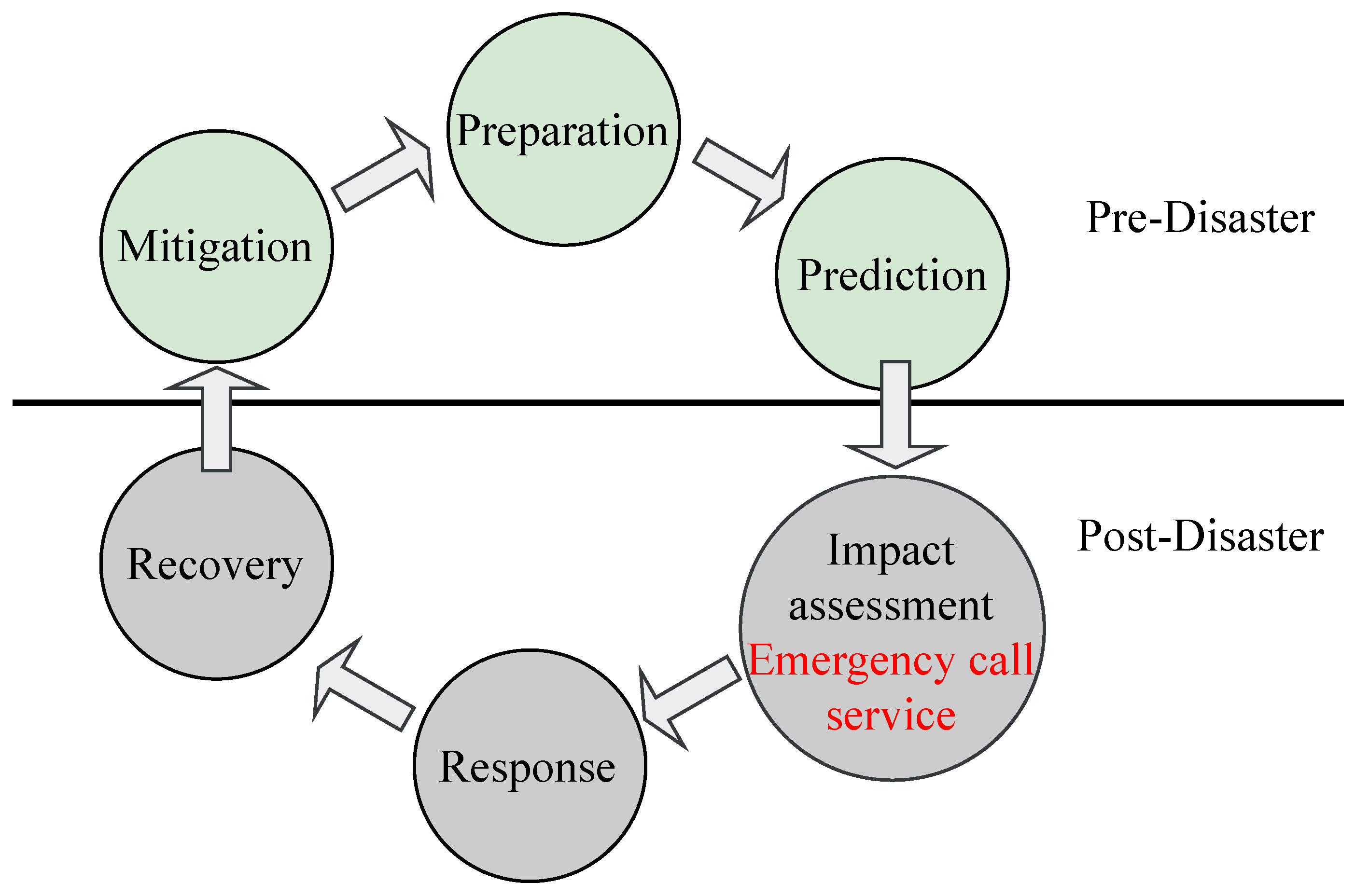
A self-adaptive, efficient, and easy-to-access emergency call service is paramount during a large disaster. During a disaster, impacted people face the risk of not being rescued on time when the number of victims increase and the network infrastructure itself is impacted. Although it is difficult to prevent natural disasters and pandemics such as Tsunami in 2004 and COVID-19, a proper disaster management scheme allows us to mitigate their effects and improve the impact assessment and response phases in the disaster management cycle [1,2,3], as depicted in Figure 1. In this context, cellular networks play a key role in providing the easiest and fastest ways to receive emergency data and provide safety services.
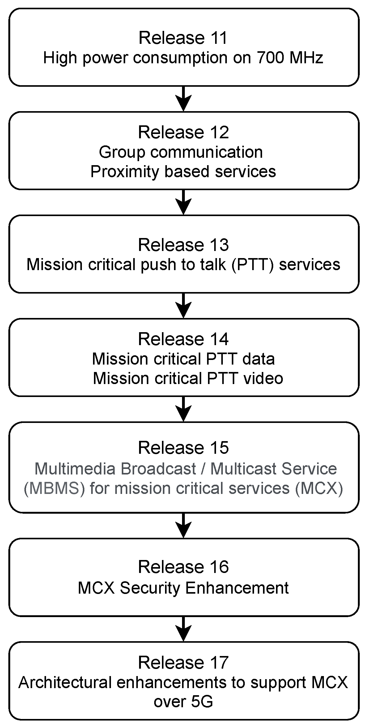
Many applications and protocols [4,5] are proposed for public safety services based on cellular network technologies [6]. Since Release 11, the third-generation partnership project (3GPP) developed the specifications of new protocols and services for supporting public safety services. The evolution of such specifications with their respective 3GPP release are illustrated in Figure 2. In general, public safety services use a narrow band terrestrial trunked radio (TETRA)-based system that can only support voice services [7] and concern-specific devices. In addition, the emergency data about the victims provides crucial information for rescuing actions in the impact assessment phase. Hence, it is important to maintain connectivity among user devices, i.e., potential victims, in such a manner that all the emergency messages get collected reliably.
Furthermore, 4G/5G device-to-device (D2D) technology allows the connectivity among user devices enabling the extension of the radio coverage of gNodeBs (gNBs) during disaster scenarios. Despite the works on D2D during disaster scenarios, the real implementation of such solutions faces two major challenges. The first challenge is the cohabitation of D2D communications and the traditional uplink/downlink communications [8]. Emergency call service should be light enough and should not interrupt the normal functioning of the user phones. Secondly, the proposed emergency call protocol should manage traffic fluctuation and radio resource access in a fully distributed way, when the network infrastructure may be damaged.
Thus, a fully distributed, feasible, and adaptive emergency service is required when network infrastructure failures occur during large disaster scenarios. Hence, in this paper, an adaptive call protocol is proposed for emergency scenarios. On the whole, the main contributions of this work are summarized as follows:
- A novel 3GPP and 5G New Radio (5G-NR) compatible emergency call protocol named 5G StandalOne Service (5G-SOS) is proposed. This protocol is designed to forward emergency calls autonomously and reliably to the network infrastructure during massive network failures using multi-hop D2D relaying across the sidelink channel. This protocol generates zero additional control traffic, is fully distributed, and is adaptive to local emergency call congestion.
- The proposed 5G-SOS protocol is designed to utilize distributed learning and adapt its parameters according to the observed neighborhood emergency call congestion data. Further, it is modeled to use the prior knowledge of local network congestion limits to assign values to the protocol parameters such that the transmission reliability and efficiency are enhanced.
- Feasible algorithms are proposed for the user devices to follow the 5G-SOS protocol and function as either an emergency or a relay device at a given instance.
The remainder of this paper is organized as follows, Section 2 provides an overview of other related works, while Section 3 and Section 4 explain the system model and proposed design of the multi-hop emergency calls service protocol, respectively. Section 5 provides the performance analysis and comparison with existing protocols and Section 6 concludes the paper.
2. Related Works
The following review of the literature confirms that specific initiatives are required for emergency disaster management. Multiple performance metrics, e.g., end–end latency, availability, deployability, energy consumption, stability, and security, determine the success of such solutions.
2.1. 3GPP Works on Public Safety
Two main approaches in Mission Critical services were introduced by the 3GPP group concerning proximity-based services in 4G/5G mobile networks; extending the gNBs coverage by using the D2D [11,12] and supporting the group calling communication, also referred as push to talk (PTT) service [4,13]. PTT is described in TS 22.179 of the 3GPP standard [14,15]. Although the PTT and D2D mechanisms present a way to extend the network coverage and services; these technologies are conceived for well-deployed local mobile networks. An extended networking protocol using such mechanisms is required for implementing an emergency call service under extreme situations, i.e., a high number of emergency calls, the partial failure of the network, and a large affected geographical area, to reliably forward calls to the core network.
2.2. Wireless Network Recovery
Multiple works of the literature [5,16,17] address the resilience and self-adaptation of the mobile networks to face a disaster affecting the network infrastructure using various mechanisms. In Table 1, the research works on recovery solutions for wireless networks are presented. The extended architecture-based approaches complicate the 3GPP compatibility in communications and add extra infrastructure costs. In this case, external or movable physical units, such as satellite [18] or unmanned air vehicles (UAV) [19,20,21,22], are deployed to rapidly work as a stand-in for damaged network facilities.
Moreover, resilient architecture-based approaches are less disruptive to the 3GPP specifications. In [23], the authors proposed to relax the dependencies between UEs, gNBs, and the core network. The objective is to provide more resilience against link disruptions by using the virtualization/redundancy of the links and functionalities. Although this approach is efficient for localized perturbations, it remains inefficient when the disaster impact is over a large geographical area. The application-based approaches try to manage the reliability and robustness issues on the service layer [24,25]. The application has to detect the communication failure and has to adapt the transfer mode accordingly (use of other wireless technology, other coding schemes, data substitution, etc.).
The resilient protocol-based approach is widely discussed for ad-hoc networks [26,27]. However, those protocols are incompatible with 5G network specifications. Some resilient-based protocols compatible with the 3GPP standard are proposed such as [28,29]. Nevertheless, most of these protocols can not be used in an out-of-coverage situation when the disaster affects the network infrastructure.
Even if dealing with disaster situations is well studied in ad-hoc network literature [30,31,32], the projection of those solutions over 4G/5G cellular standards is rarely studied and remains difficult. Furthermore, the user equipment (network nodes) is not owned by the system itself, making the protocol possibilities more regulated and constrained than in private/community networks such as MANET and VANET systems [33,34].
Meanwhile, the FINDER protocol in [10] represents one of the rare works on the massive use of D2D mechanisms to overcome large disaster situations. In FINDER, emergency calls are forwarded to working gNBs by clustering and organizing the out-of-coverage mobile devices. There is a cluster head (CH) in each cluster that is selected by the members of the cluster. The CH receives emergency calls transmitted by mobile nodes within its cluster. The CH aggregate and transmit them across the neighboring CHs to the nearest active gNB via multi-hop D2D communications. The procedure suffers from the complexity of cluster computing and the lack of resilience against cluster head failure. On the other side, the use of personal UEs to serve as cluster heads is not practical.
On top of that, M-HELP [9] is another resilient protocol designed to address large disaster scenarios using D2D. M-HELP adds zero additional control messages to the network. Further, it has been shown that M-HELP has a better performance in terms of successful transmission reliability, network congestion, and residual energy compared to FINDER. However, the robustness of M-HELP remains a challenge under scenarios with varying emergency call loads, scale of disaster, D2D transfer delays, and UE densities. Hence, a novel protocol is proposed to improve the robustness of emergency call protocols under extreme emergency scenarios using observed neighborhood network data.
3. System Model
An overview of the system model considered to design and implement an emergency call protocol named 5G-SOS is presented in this section. In this work, it is assumed that all UEs ∈ M are 4G/5G emergency service enabled. In such a network area, each UE can behave both as an emergency call initiator and as a relay. Since a disaster scenario is evaluated, it is assumed that the UEs are stationary and their location is fixed at the initial period just after the disaster.
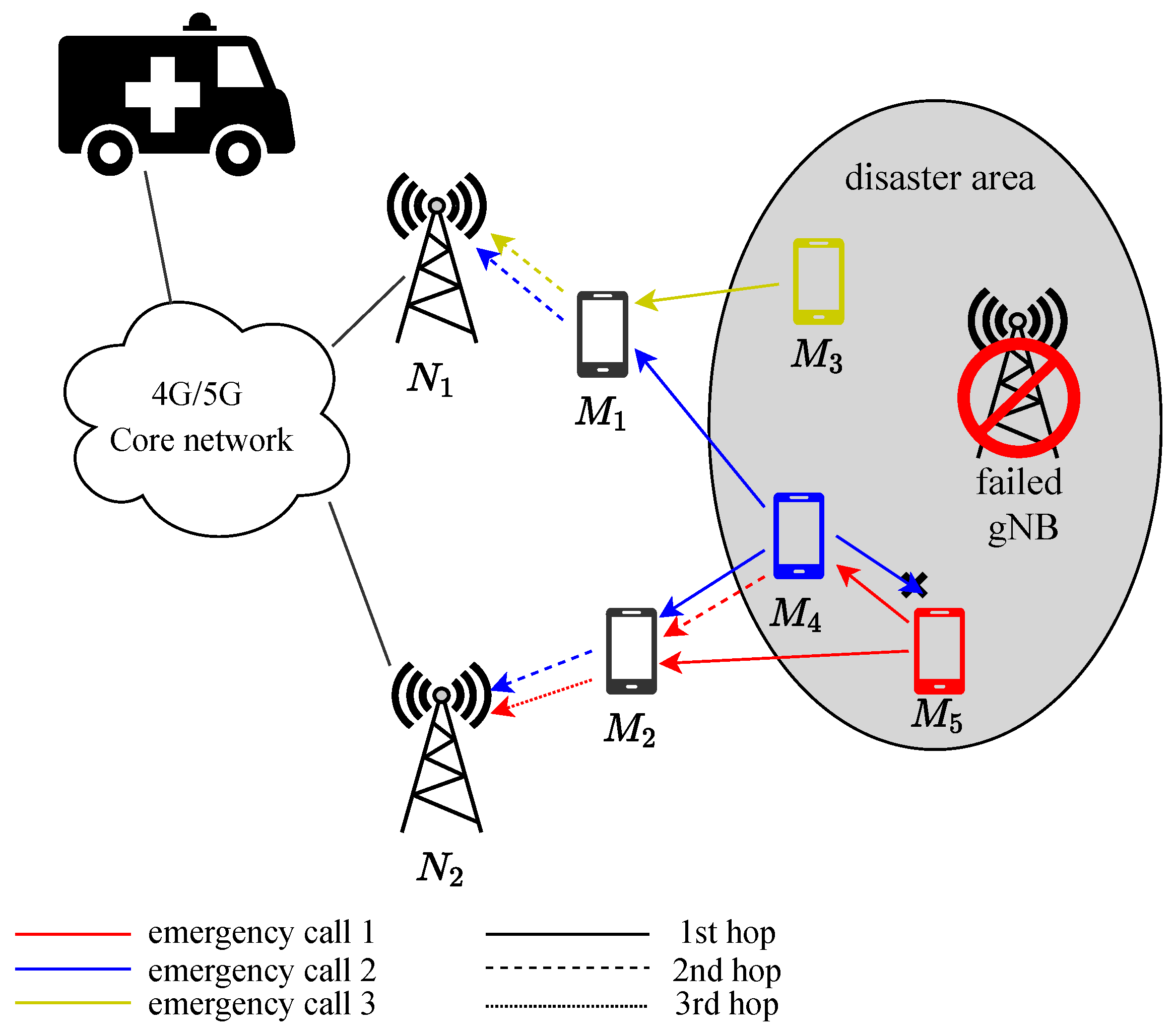
Furthermore, two modes of emergency call transmission, D2D and classical, are utilized to forward emergency calls to the network infrastructure, as illustrated in Figure 3. In this example, three UEs (orange, blue, and red) are in an emergency and are out of coverage due to the failure of the covering gNB. The orange UE sends a broadcast D2D message that is only received by one UE and then relayed in the classic mode to the operational gNB at the top of the Figure. The emergency call of the blue UE is sent in D2D mode and is received by three UEs. The two relay devices in black transfer the emergency call to both working stations, while the red UE ignores the blue UE’s emergency call because its RSSI is worse than the blue UE. The red UE diffuses its emergency call to the blue UE, which relays it to all neighboring UEs until the emergency call reaches the working station at the bottom of the figure. The transmission redundancy allows improving the reliability of the protocol. However, the number of copies of the same message has to be controlled to prevent radio network saturation.
3.1. Informational Model
Each device is characterized by the following data:
- Current battery level (residual energy), ;
- Coverage status by at least one gNB, :The coverage status indicates if the UE has at least one direct communication link with a station , allowing it to communicate directly with the core network. When a UE is out of coverage, it no longer has a direct connection link with the gNBs.
- GPS localization accuracy, :Location information is obtained using a global positioning system (GPS). It is assumed that the error in such a GPS measurement is represented by the distance between the actual position and the estimated position of m, measured in meters. Hence, is modeled as (1),
- Received signal strength indicator (RSSI) power that is detected, :The broadcast physical layer synchronization signals (PBCH) periodically transmitted by the operational gNBs enable the UEs to establish quality indicators, including RSSI, reference signal received power (RSRP), reference signal received quality (RSRQ), signal to interference plus noise ratio (SINR) and channel quality indicator (CQI) up to 75 km from the gNB [35,36]. These measured indicators are useful in the selection of the best paths toward the nearest operational gNB.The RSSI indicator [37] is measured by each UE to estimate the strongest signal received from the surrounding operational stations as shown in (2). The RSSI value depends on device location and more specifically on the signal path loss [37] between the gNBs and the device. Signals’ path loss, namely , is varied due to the propagation parameters such as the distance between gNB and receiver UEs, height and location of UEs, transmission frequencies, terrain contours, environment.where is the power of the transmitted signal by a given station n. represents the set of radio resource blocks used to transmit the physical broadcast channel (PBCH) signals. corresponds to the set of OFDM symbols and sub-carriers on which the PBCH is transmitted. For each operational station, the user equipment (UE) computes the average received signal power [38] over all the symbols and sub-carriers, f of . Finally, the UE only considers the highest computed average.
3.2. Emergency Call Procedure
The emergency call procedure can be triggered either by human intervention or automatically (e.g., after a car accident detection). Once the call is triggered, the emergency application starts incorporating the data related to the victim, i.e., voice, text, video message, the UE id emergency call id, indicators about the emergency degree (level), RSSI indicator, and device position. If the emergency caller is within the coverage of a network gNB, then the call is directly sent to the gNB using the classical communication mode. However, if the caller is out of coverage, the call is locally diffused using the out of coverage D2D procedure.
Once a relay receives an emergency call and decides to relay it, the relay adds its identifier, position, and RSSI value to the relayed message. Then the relayed message is sent using either the traditional mode if the relay is covered by a gNB or by D2D communication if the device is out of coverage. The emergency source position and relay’s positions help the public safety center precisely localize the source of the emergency call. Further, once an emergency call is received by a given gNB, a notification is diffused to all the UEs under coverage, indicating the successful transmission of that emergency call with its specific ID. That way, redundant uplink transmissions of the same emergency call are reduced.
3.3. Outband D2D Communication
When the sender is out of coverage, the emergency call source or relay sends a control message via the physical sidelink control channel (PSCCH). The PSCCH serves, implicitly, to synchronize the sender with the potential receivers. It is used by ProSe-enabled UEs to send the sidelink control information (SCI) that informs the receivers about the data transmission parameters used during the next sidelink period: subframes and radio resource blocks [39]. More precisely, the PSCCH indicates the index of the used subframes (time), the used radio resource blocks (frequencies), the modulation and coding scheme, and the D2D group destination ID. Each UE listens continuously to the PSCCH channel to detect if another UE is transmitting in the current sidelink period. Once the PSCCH message is received, the relay node tunes to the corresponding resources in the physical sidelink shared channel (PSSCH) to receive the emergency data.
In summary, an outband D2D multi-hop model based on 4G/5G sidelink communication is considered for emergency call forwarding. This model, called the 5G-SOS protocol, is described in the following section.
4. Adaptive Multi-Hop Emergency Call Protocol: 5G-SOS
The 5G-SOS protocol aims to maximize the probability that the emergency call reaches at least one gNB with a minimum delay and with a reasonable number of exchanged messages. The 5G-SOS procedures and adaptive parameters used by an emergency device and relay device are presented in Algorithms 1–3. The notations used in the Algorithms are presented in Table 2.
As detailed in Algorithm 1, when an emergency UE, E, generates an emergency call, DATA, the application layer constructs a data message, including the emergency data (rescue video, voice, or text), GPS localization, observed RSSI and a couple of value and . DATA.srcID corresponds to the identifier of the source of the emergency call, E. is the internal identifier given by E to the emergency call using the function callIDGenerator. means that whatever the two different emergency calls initiated by E are, they have different .
If the emergency phone, E, is under the coverage of a given gNB, then the emergency call is sent using the traditional 4G/5G uplink communication (PRACH and PUSCH channels). Otherwise, a D2D communication procedure is opted. First, a PSCCH message is sent announcing that emergency data will be sent during the next sidelink radio frame period. The parameters included in PSCCH inform the receivers about the subframes (TRP) and frequencies (RIV) used to transmit the emergency data over the PSSCH channel. The destination group ID of the PSSCH is set to “ANY” since it concerns all neighboring UEs.
Next, the emergency phone E counts the number of times its own call is relayed by the neighbors (see lines 10–17 of Algorithm 1). To do so, each DATA is identified by the exclusive couple of values . If the received message by the R is its own message (the same couple ), then the number of relay neighbors, , is incremented. If, after a period of , the DATA is resent until the maximum number of re-transmissions, , is reached. Every attempt is considered a new emergency call by changing the DATA.callID identifier of the message.
| Algorithm 1 On emergency call generation |
|
| Algorithm 2 On receiving an emergency call, DATA |
|
| Algorithm 3 Every one second |
|
As described in Algorithm 2, once an emergency call is received, the relay device, r, studies the opportunity of forwarding it. First, r checks if the of the received DATA is in the already received calls list, . If it is a new emergency call, r stores the received message in the list of considered calls, . allows managing up to three emergency calls simultaneously. Each emergency call in is associated with two new fields: and . is initialized to 0 and stores the number of times that the message DATA is relayed by other neighbors. gives the limit date of the call in . is computed using the maximum waiting duration, , as shown in line 5 of Algorithm 2. If the received message is already received (line 9 of Algorithm 2), r checks if the message belongs to the being considered messages . If so, the number of times the waiting call is relayed is incremented and the call is removed from if this number reaches the relay threshold .
Every second, the relay phone r checks its list as explained in Algorithm 3. If the waitingCall.deadline of a being-considered call, , is reached, then the call is relayed after including, in the field, the relay’s data, such as the RSSI, GPS location, and srcID and in the content of the received call . According to whether r is in-coverage or not, the DATA is transmitted using the classic or D2D mode. Moreover, only one emergency call is transmitted at a time and each device is associated with a state variable (my State) initialized to “idle”. When the device starts to transmit an emergency call, the state is turned to “busy”. During the busy state, the device continues to receive and queue emergency call requests.
4.1. 5G-SOS Adaptive Parameters
The behavior of existing protocols such as M-HELP [9] depends on constant parameters mainly used by the UEs to decide either to relay or not, the received emergency calls. In contrast, 5G-SOS parameters are designed in the proceeding sections, which can vary adaptively according to the observed network measurements.
4.1.1. Waiting Time for Relaying,
The role of the waiting time is to define an order between the relay devices in a fully distributed way. A short means that the relay device is suitable for relaying the emergency call. When the is long, the device relays the call only if necessary, i.e., the neighbor relaying is not sufficient. In other words, UEs with a low , out of coverage, low RSSI signal, or with poor localization accuracy wait longer before deciding to relay the received emergency call. Therefore, longer allows the UE to wait for the decisions of more suitable devices. To prevent a very long waiting time, a maximum waiting time is introduced. In M-HELP [9], the waiting time is computed as (3):
where the coverage state, localization accuracy, and residual energy of r is given, respectively, by , and . In the M-HELP protocol, was fixed to a specific value. However, it is clear that the value of should be adapted according to many factors such as the observed emergency call rate and the UE density. That is why the computation of the value is adjusted as follows:
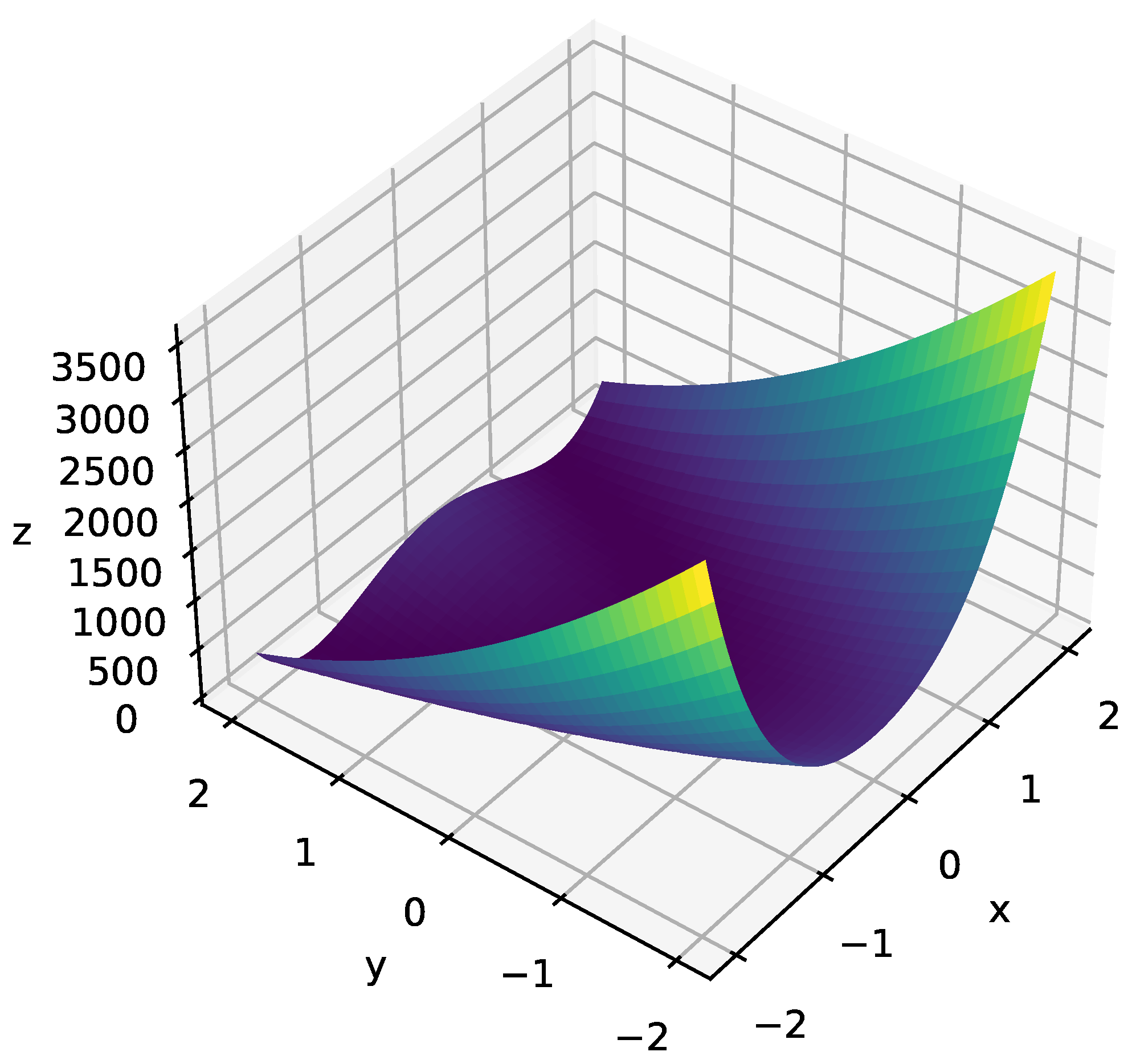
The parameter is now expressed by a modified Rosenbrock [40,41] function. Moreover, Rosenbrock function is used often as a test problem for optimization algorithms. Further, Rosenbrock function is used in this work seeing that it has a slope with the same behavior to given in Table 3). The Rosenbrock function given in (5) is modeled to increase the sensitivity of protocol to the real-time local factors such as the amount of emergency requests and neighborhood congestion detected in the previous minute.
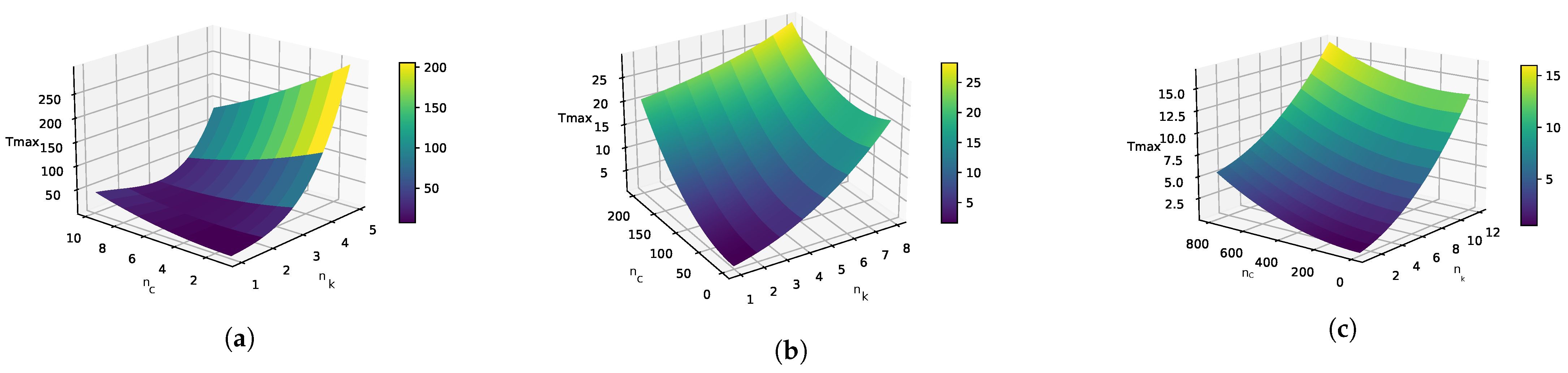
where represents the total number of received emergency requests, including multiple receptions during the last minute. is used to measure the level of congestion in the neighboring environment in the past minute. Further, measures the total number of different emergency call requests received in the previous minute. In addition, a and b are two parameters that govern the shape of the Rosenbrock function in (5).
A low number of distinct emergency calls with a high congestion level expresses a low emergency load but with many relaying opportunities for each emergency request due to the network density. In this case, a high value allows to better select the relevant relays. However, if both and are low, the value is decreased since there are not enough relay alternatives, i.e., a weakly dense network. Finally, when is high, a lower is preferable in order to quickly handle the newly received emergency requests. Further, if the number of neighboring relaying devices is less and such devices have a low battery level, they will be assigned a relatively shorter by 5G-SOS based on the low neighborhood congestion.
The expected adaptive behavior of according to and is summarized in Table 3. The curve of the original Rosenbrock function, f, is given in Figure 4. When x increases while y is fixed, increases. However, when y is increased, while keeping x fixed, decreases gradually.
To compute the waiting time , r uses its coverage state , its localization accuracy , and its residual energy . However, (3) and (4) show that the protocol 5G-SOS introduces the use of RSSI in the computation of the waiting time parameter. The ratio between the of the transmitter device that sent the call request, and the of the r itself is computed. This ratio is higher than 1 when the transmitter of the emergency call is in better radio conditions than the receiver (farther from the gNBs). In this case, the ratio contributes to increasing the value of in order to penalize the receiver in its selection for relaying the emergency call. Otherwise, when the ratio is less than 1, the receiver is in better radio conditions (closer to the gNB), and the waiting time is decreased to give priority to the receiver.
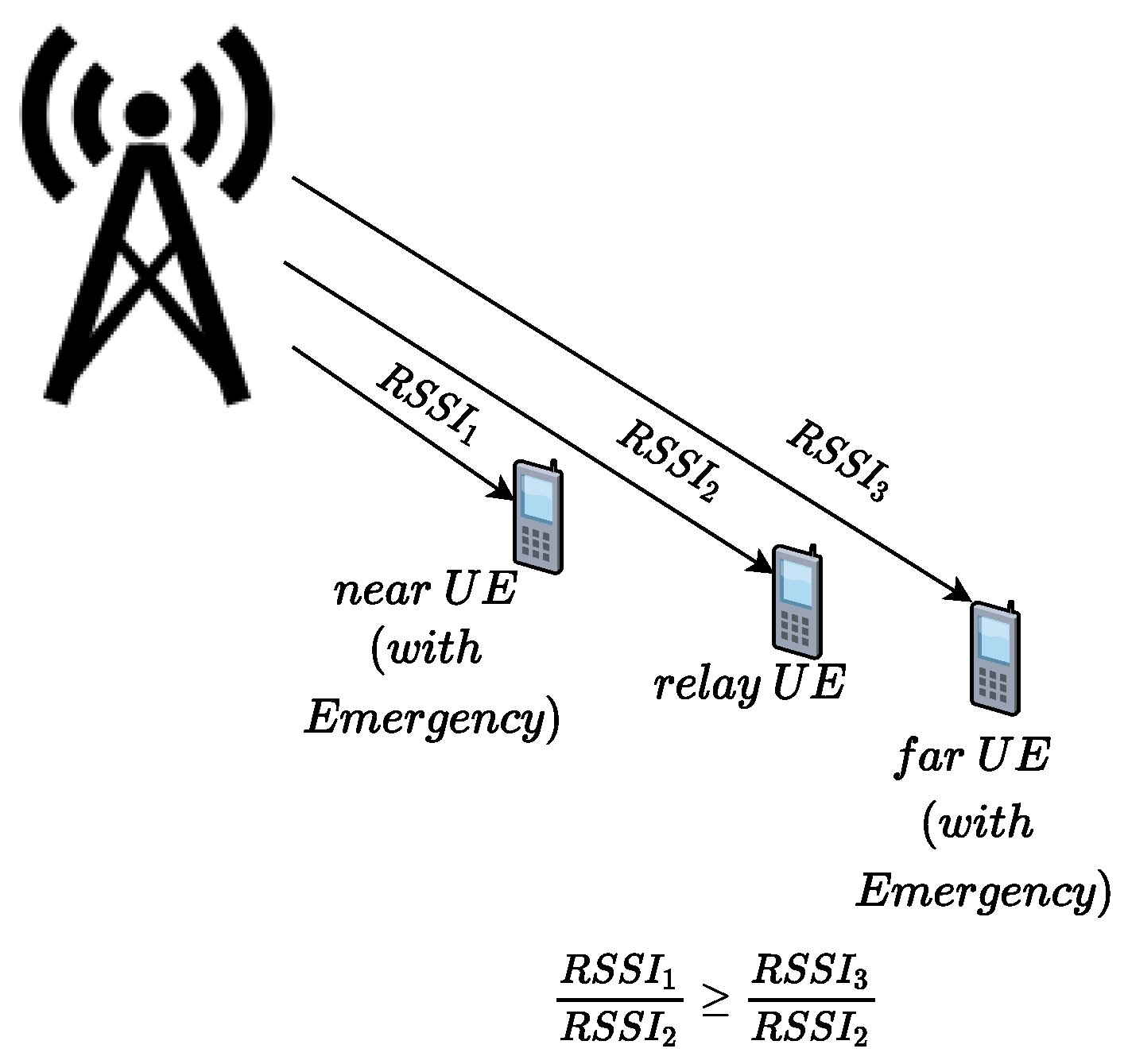
The RSSI ratio is used to improve the latency fairness between UEs. Indeed, a relay device waits less time when the request is sent by a farther device than when the request is sent by a closer device, as depicted in Figure 5. Therefore, when two requests are received at the same time, the request of the farthest device from the gNB is transmitted first, which contributes to balancing the emergency call transfer delays.
4.1.2. Relaying Threshold,
The parameter is a critical parameter that determines the balance between the reliability of the communication and the fairness in transmitting distinct emergency calls. If the of an emergency call is high, the probability that the call reaches a gNB becomes higher. However, under a dense network and/or a high number of emergency calls, increasing the number of relay thresholds may lead to saturation of network devices in the busy state, and many interferences. Late emergency requests are penalized or rejected since the first emergency requests remain longer in the pending requests list . In the 5G-SOS protocol, a device adjusts the value of its according to the real-time conditions following the expression:
4.1.3. Waiting Time for Re-Transmission,
As seen in Algorithm 1, the source of the emergency call waits a period of time to check if sufficient devices have relayed emergency calls. The computation of the parameter follows the same behavior of since the retransmission delay has to align with the of the neighbor devices in order to prevent losing the retransmitted call in the neighborhood. Consequently, is modeled as (7):
4.1.4. Emergency Call List
The 5G-SOS protocol-enabled device uses two kinds of lists to store the history of received emergency calls in the buffer. In the list, the device stores the identifiers of received calls represented by the couple , while the data of the emergency are not stored. To prevent the excessive increase of this list, the emergency calls are removed from the list after a given period (30 min). In the second list, , the device stores the pending received emergency calls. A call is removed from when the expires and the call is relayed by the device, or when the call is sufficiently relayed by neighboring devices. The size of is limited to three calls. If the limit size is reached, new emergency calls are ignored as presented in Algorithm 2. The use of is a new feature of the 5G-SOS protocol. In the M-HELP protocol, only one emergency call is processed by the device at a given time. All emergency calls received during the transmission of a previous emergency request or during the pending period before relaying a previous emergency call are ignored.
In order to investigate the performance of our protocol, we evaluated and compared 5G-SOS with the existing M-HELP [9] and FINDER [10] protocols under extreme emergency scenarios. Thereby, the 5G-SOS testing environment, evaluation parameters, and performance analysis are presented in the next section.
5. Simulation Results
5.1. Test Environment
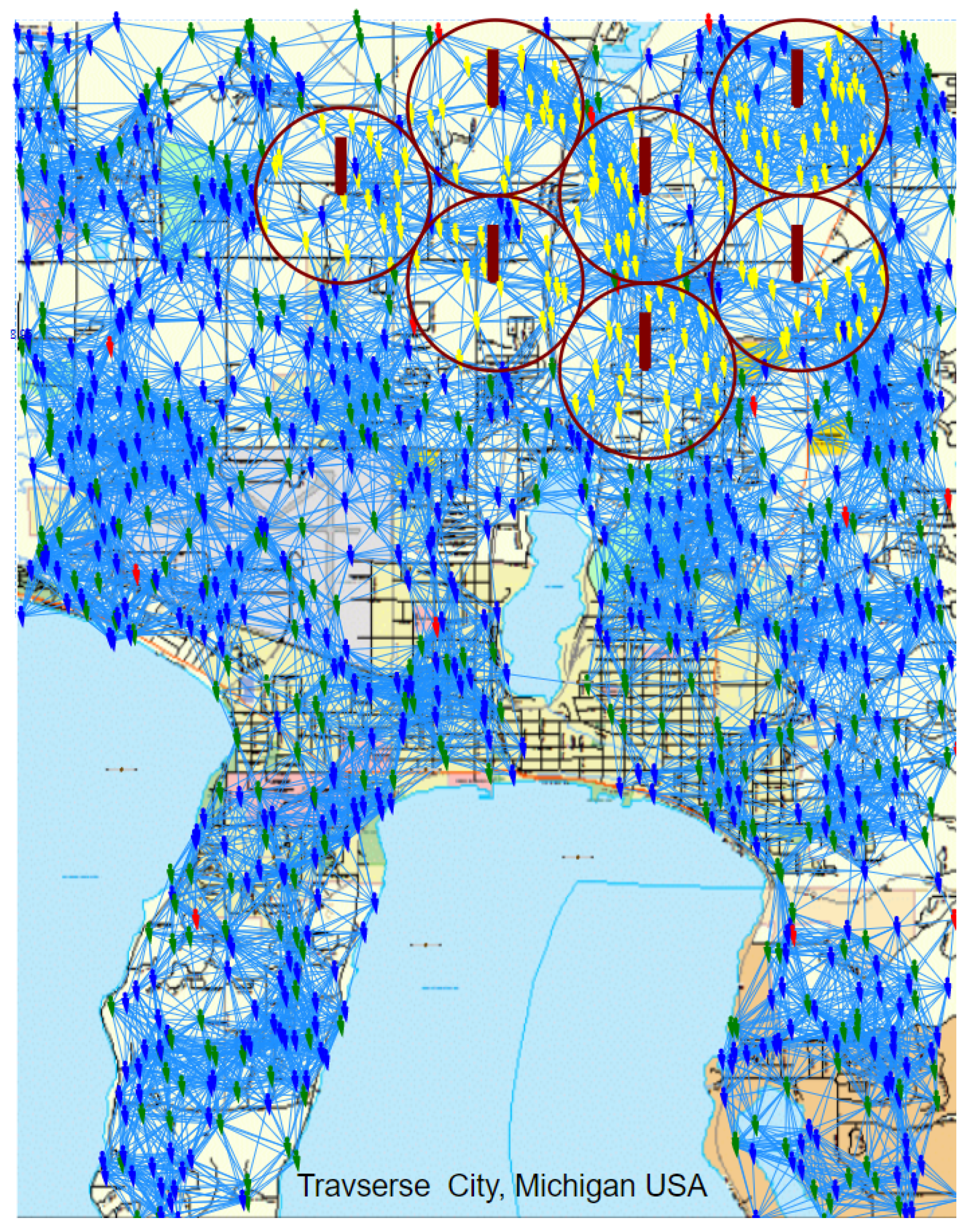
The performance of the proposed 5G-SOS is assessed in AnyLogic® software. An emergency scenario in the Transverse city in Michigan, USA, with a number of devices varying between 5000 to 15,000 and 7 working gNBs covering an area of is considered. This scenario is illustrated in Figure 6.
5.1.1. Propagation Pathloss Model and RSSI
In 4G/5G networks, operational gNBs periodically broadcast control signals, PBCH, over predefined resource blocks. The RSSI of such signals is computed using (2), where represents the path loss of the signal due to environmental factors, i.e., buildings, mountains, etc. To compute the in (2), the Cost231 propagation model for semi-urban areas, given in [42], is used. of a signal transmitted by a working gNB varies according to the signal transmission frequency of the working gNB, f, and the distance between the working gNB and receiver UE, d, as given in (8). Further, and represent, respectively, the height of the gNB and receiver UE. is a correction offset associated with the semi-urban environment. For the simulations, f is set to 885 MHz. varies according to the used frequency, f, and the distance between a functioning gNB and a receiver UE, d, is modeled using (8) and (9). Further, the measured values of RSSI are handled in Watts.
with:
5.1.2. Neighbor Realying Threshold:
The maximum threshold for neighbor relaying, , is set to a constant and denoted the number of pending call requests in the UE buffer. The latter is used to estimate the number of different emergency calls being relayed in the neighboring area. Further, the maximum limit for is assumed to be a constant. Hence, when the value of changes from a minimum to maximum, the adapts its value according to (6). In comparison, the value of is fixed in the M-HELP protocol.
5.1.3. Rosenbrock Parameters
5.1.4. Limits of
The limits of are determined by applying M-HELP in each individual device in the network devices. Further, the observed under 100 random replications are collected. The minimum and maximum limits of for different device density values such as 100, 1000, and 4000 are gathered and used as limits to be observed by an UE given in Table 4.
5.1.5. Evaluation Criteria
The following metrics are considered to assess the protocol performance.
- Success rate represents the ratio between the number of emergency calls received successfully by at least one gNB/eNB and the total number of emergency calls given by (10).
- End–End Latency (EEL) is the average delay between emergency call generation and its first successful reception by a gNB. EEL is measured in seconds and includes all the delays caused by processing, buffering, temporizing, and transmission times given by (11).
- Number of messages per node, , represents the average number of relayed emergency messages per device given by (12).
- Energy consumption per node, , measures the average energy consumption per device as given by (13). This includes the energy consumed for the transmission and reception of emergency calls.
5.2. Performance Analysis
In this section, the performance of 5G-SOS is studied and compared with M-HELP [9] and FINDER [10] under multiple disaster configurations while 75% of the gNBs in the network area are out of operation. The emergency calls are randomly generated in a uniform distribution, over an emergency occurring time interval (ETI) of 30 min. Further, the performance is assessed by considering that all nodes are stationary. Moreover, for the network protocols considered in this work, if the network nodes do not form a connected graph, emergency calls cannot reach the gNBs during a single emergency call initiation. Hence, the D2D link connection range is set in order to maintain such a connected network. Furthermore, the number of UEs (NoU) and number of emergency calls (NEC) satisfy the condition, NEC < NoU. The provided results are all averaged over 100 random executions, which differ by the source devices at which the emergency occurs and emergency arrival times. Table 5 summarizes the parameters used in the simulation scenarios. The emergency data transfer takes seconds. During the emergency call transmission (D2D transmission or ordinary transmission) the UE cannot transmit other emergency requests.
5.2.1. Scenarios and Tests
Extreme emergency scenarios are considered to assess the performance of 5G-SOS. In particular, success rate, , , and metrics under extreme emergency call duration, device density, data size, and emergency call number are studied.
5.2.2. Impact of Emergency Call Duration
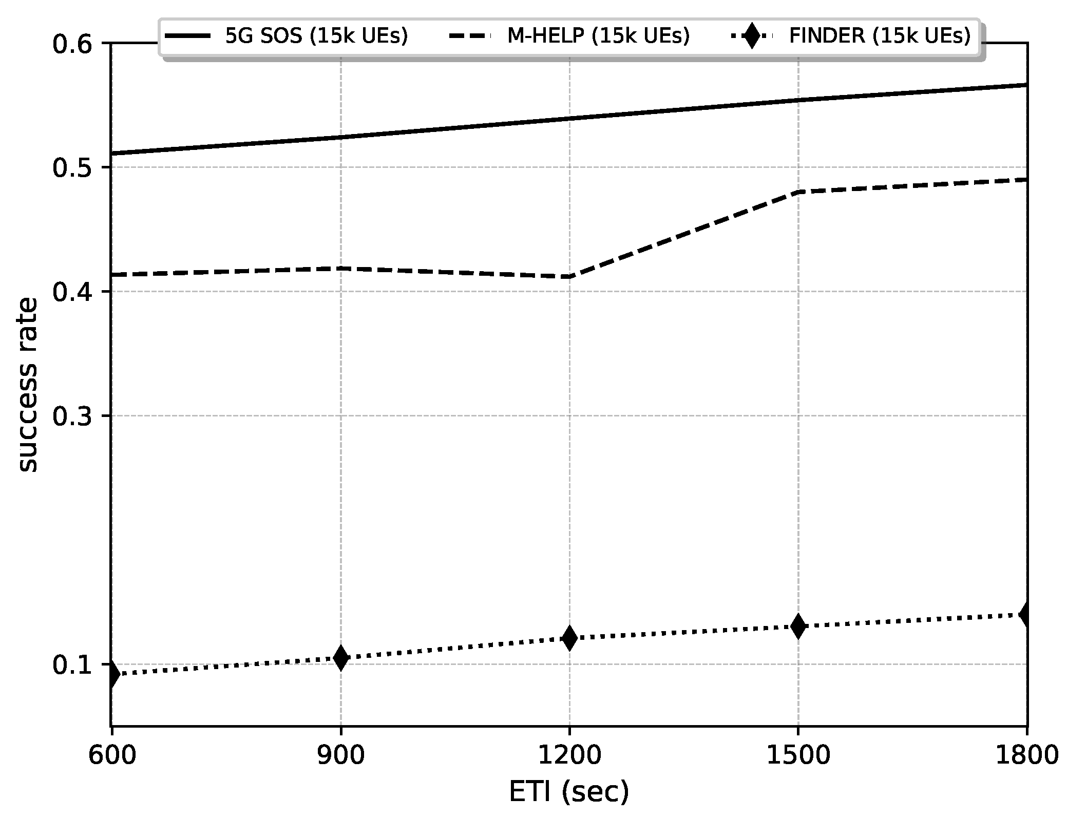
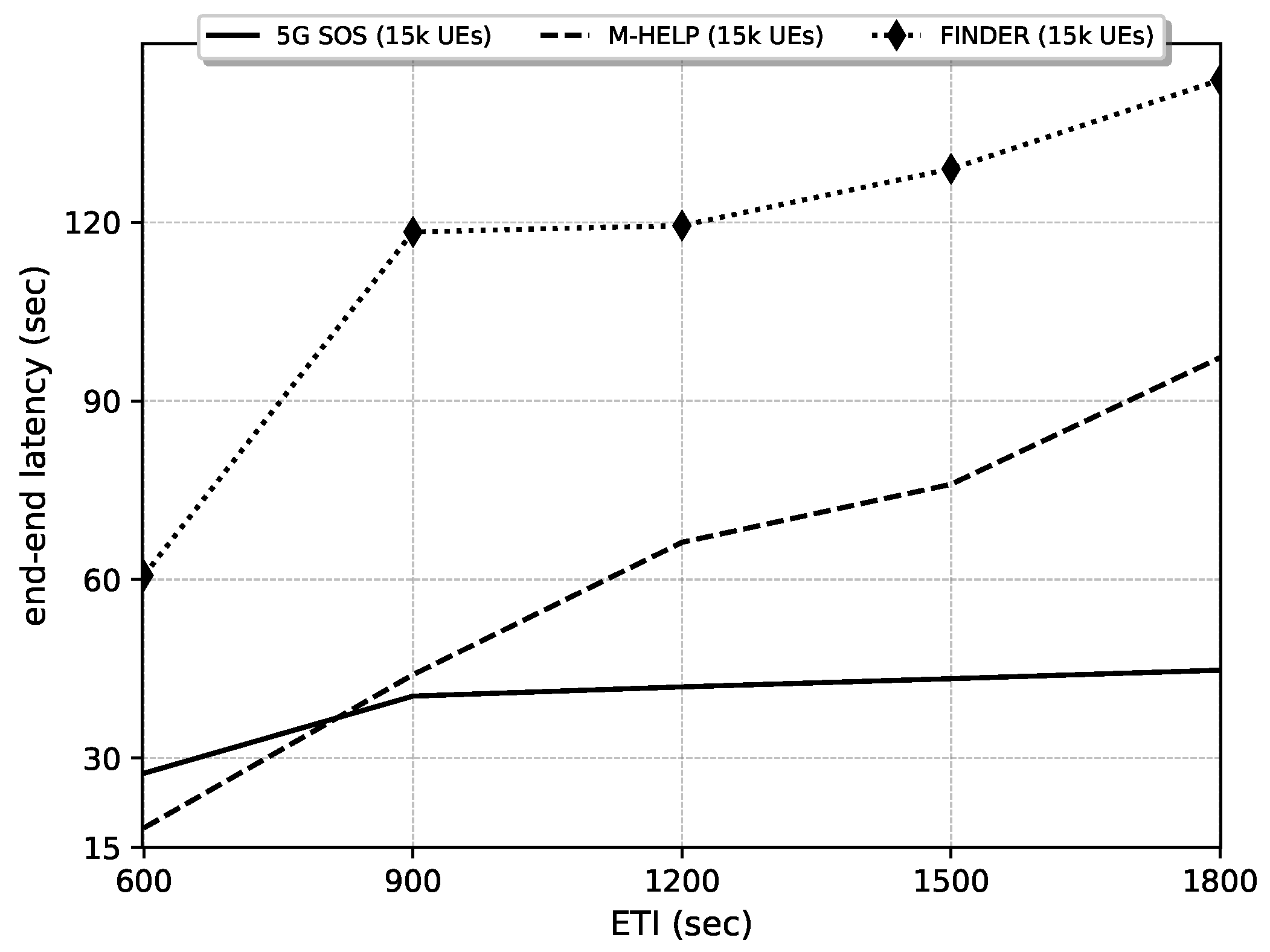
The impact of ETI on success rate and EEL is observed in Figure 8 and Figure 9. It is observed that when the emergency call arrivals are spread over a longer ETI, the amount of successful transmissions increases. As the relay nodes become overcharged due to a shorter ETI value, the probability that a node ignores an incoming request, due to the buffer saturation, increases. In contrast, when the ETI is longer, the number of idle relay nodes available to cater to each relay request is higher.
Further, it is seen that with the increment in ETI, the success rate and EEL of 5G-SOS is significantly improved compared to M-HELP and FINDER. The adaptive parameters in 5G-SOS enhance the responsiveness to a large number of emergency calls occurring in a shorter ETI. The parameters, and , are adaptive in 5G-SOS compared to M-HELP, where such parameters are fixed to a specific value. The reason for the success rate being lower in the FINDER protocol is due to devices relaying the data only to the cluster head (CH). The CH aggregates the received data and sends them to nearby CHs. Such an aggregation results in a high traffic concentration on CHs and reduces the success rate. Moreover, under each protocol, the EEL increases against the duration of ETI. As the emergency calls occur over a shorter ETI, the amount of idle relay nodes is low. Further, since relay nodes do not buffer the simultaneously received calls in M-HELP, only a few calls are successfully transferred to the gNB. Hence, initially the corresponding latency in M-HELP is low. The EEL in 5G-SOS is initially higher than M-HELP since the success rate of calls is higher and hence the corresponding latency increased. As the adaptive parameters in 5G-SOS allow the quick transferring of calls, the amount of waiting at the relays decreases and hence results in a lower EEL compared to both M-HELP and FINDER. In FINDER, the delay in allocating a cluster head and communicating calls via multiple cluster heads causes the increment in EEL, when the amount of successful calls increases.
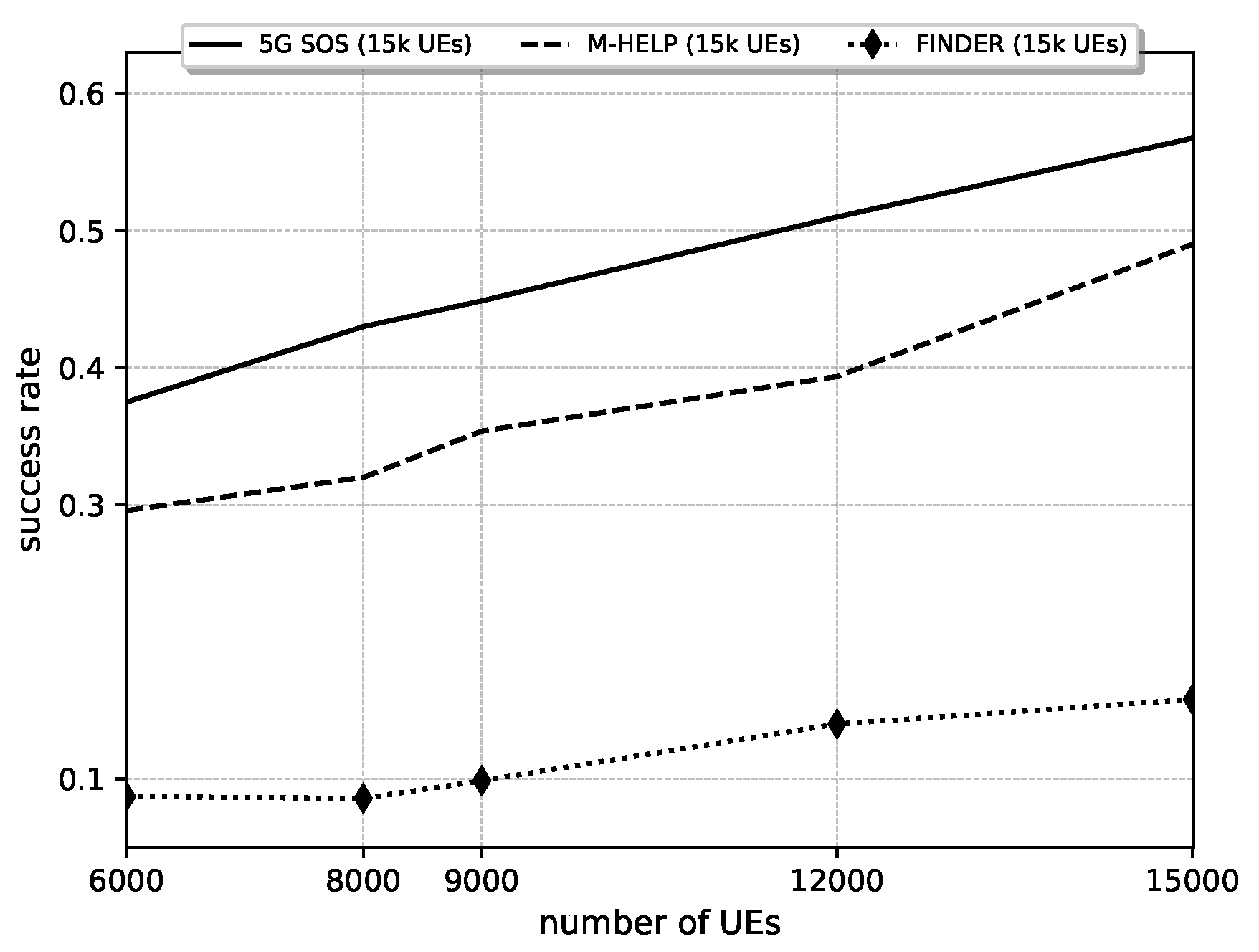
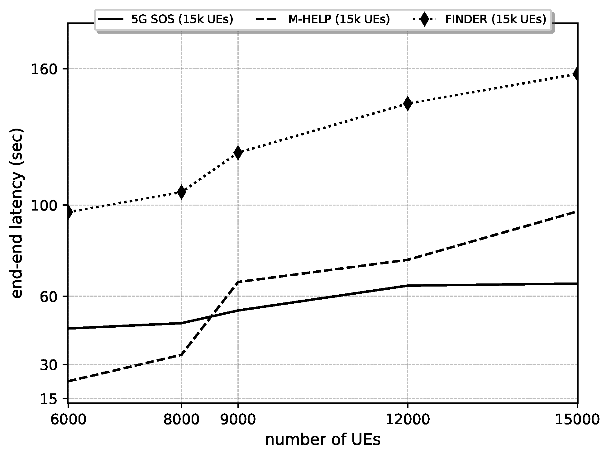
5.2.3. Impact of Device Density
In Figure 10 and Figure 11, we study the impact of the network density on the emergency call transfer under a fixed number of emergency calls and fixed emergency time interval. As observed in Figure 10, the success rate increases with the increment in the number of UEs since it increases the availability of more idle nodes under all the protocols considered. A higher number of idle nodes increases the probability of serving a large number of emergency calls compared to a low device density network. As in the previous section, initially the EEL in 5G-SOS increases compared to M-HELP, since a higher latency is consumed to achieve a higher success rate under the constraints of increasing local congestion. It is reflected in Figure 9 where the EEL increased against the number of UEs due to the increment in the local congestion and thus the waiting times in 5G-SOS. The increment in local congestion increases and causes a saturation in buffers, which result in lower relaying efficiency. However, the adaptive nature in 5G-SOS parameters allow faster relaying of calls compared to M-HELP and FINDER. It is observed that increasing the number of devices plays a positive role in the improvement of the success rate of 5G-SOS, M-HELP, and FINDER. The use of 5G-SOS significantly reduces the EEL compared to M-HELP and FINDER, since 5G-SOS uses the local congestion data, RSSI, and buffering to increase the relaying efficiency in an adaptive manner.
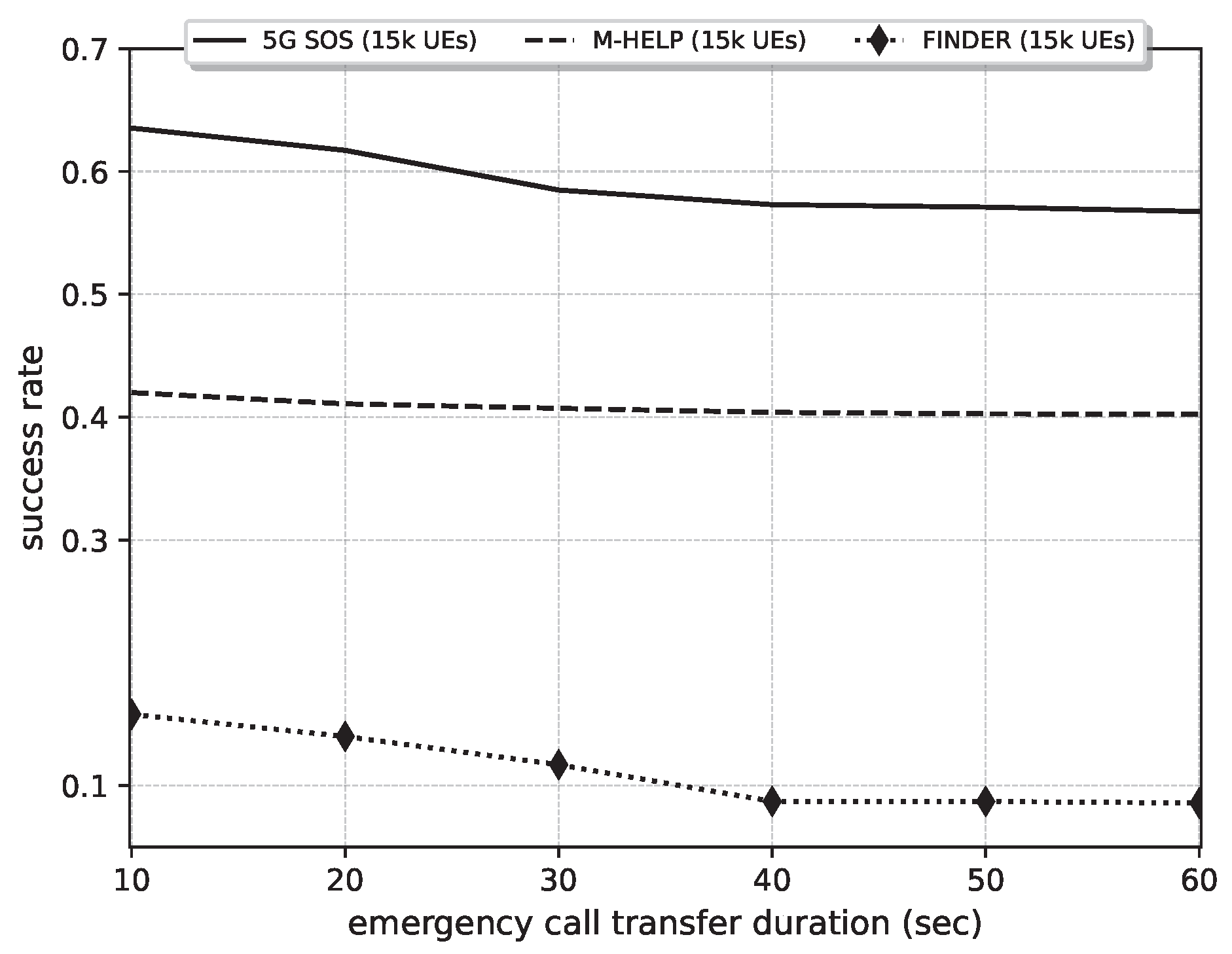
5.2.4. Impact of Emergency Data Size
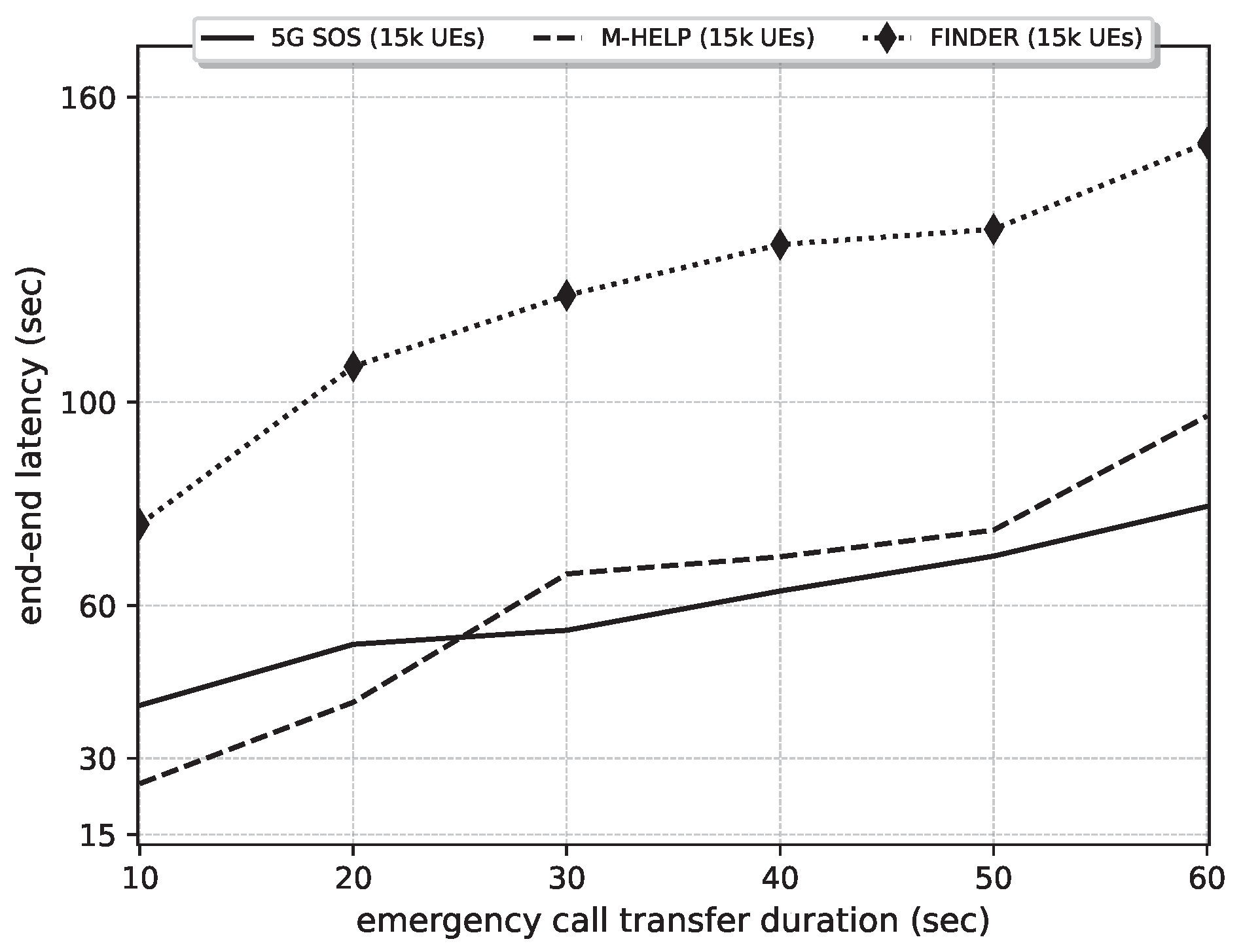
The emergency data size depends on the type of data such as text, audio, video. The emergency data size increases respectively with text, audio, and video data types. Moreover, the emergency call data size is completely correlated with the transmission duration of the emergency call (D2D or classic mode). Hence, the impact of emergency data size on the performance of 5G-SOS is observed in Figure 12 and Figure 13, where emergency calls occur within a fixed ETI. As shown in Section 5.2.4, when the data quality is low, the success rate is higher compared to transferring high quality data. Hence, it is noted that the proposed 5G-SOS is mostly suitable for a low quality data transfer, which would be convenient during disaster situations. As the duration for emergency call transfer increases, the number of busy nodes, processing other emergency calls, increases. This leads to a lower relaying efficiency and thus a drop in the overall number of successful transmissions. As expected, the latency increases in 5G-SOS. M-HELP and FINDER increase the data transfer time since the data type directly impacts the delay at each relay. Further, only one emergency request could be transmitted at a time which correspond to the delay before relaying.
5.2.5. Impact of the Percentage of the Number of Emergency Calls (NEC) over the Total Number of UEs (NoU)
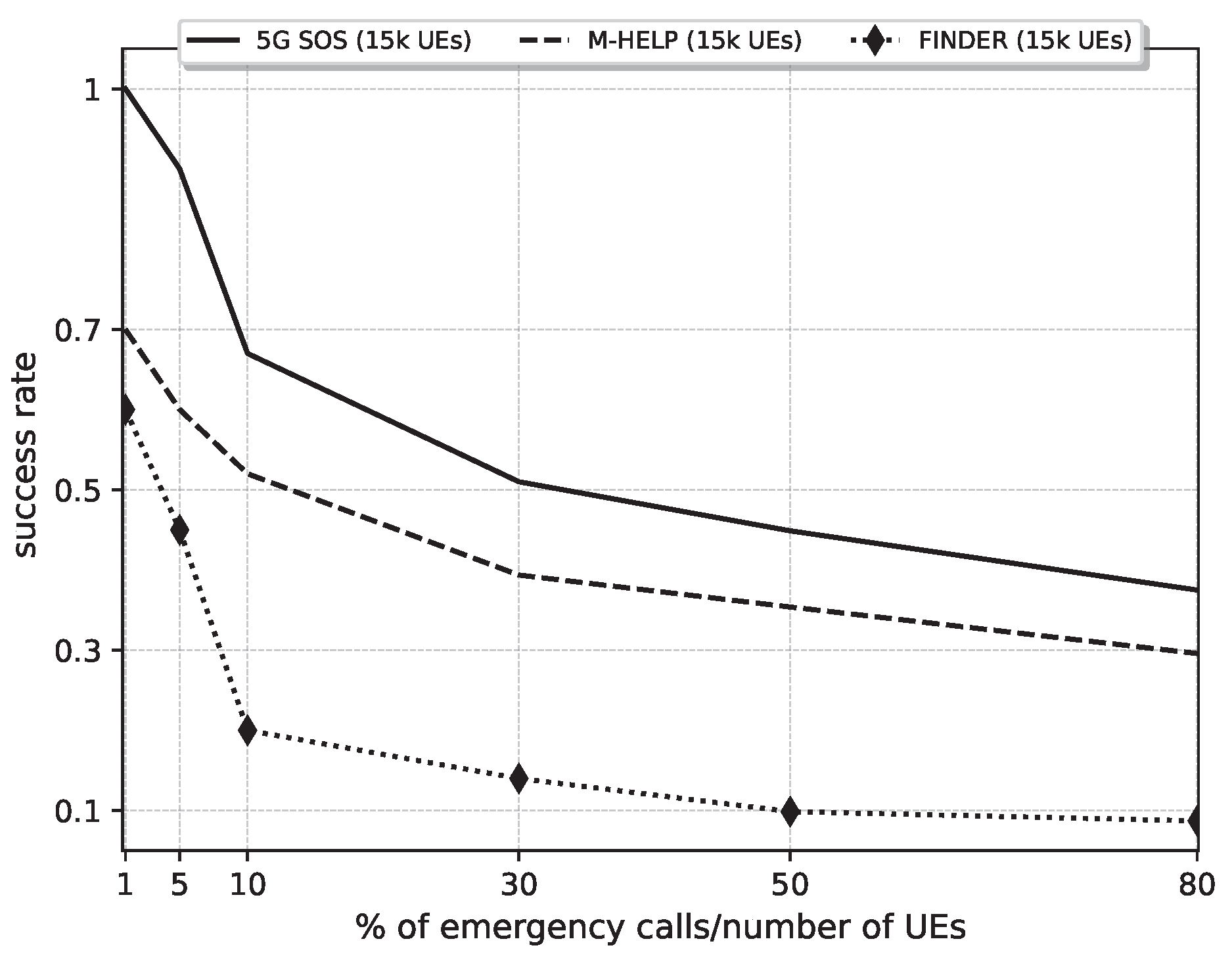
First, it is observed, in Figure 14, that the success rate of 5G-SOS is nearly 100% when the number of emergency calls are less than 5% of the total devices. Further, when the percentage of NEC over NoU approaches 80%, i.e., almost all nodes generate an emergency call, around 37.4% of calls are relayed successfully against only 29.5% in M-HELP and 8.7% in FINDER. Moreover, when 5000 emergency calls occur within an ETI of 600 s (10 min), more than 50% of calls reache the core network, as observed in Figure 8.
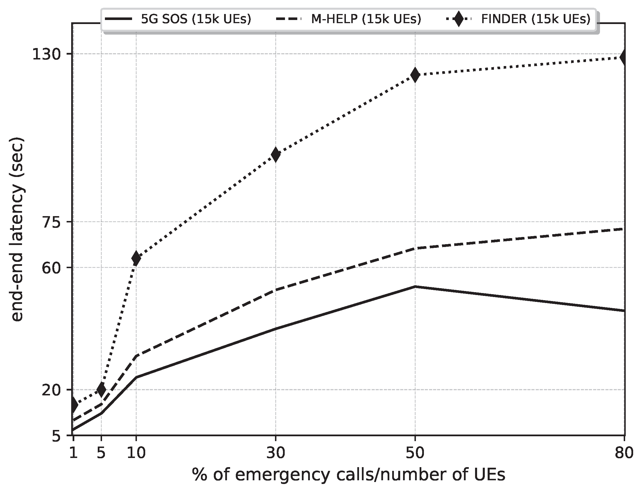
Figure 15 presents the EEL under varying NEC over NoU ratios. It is noted that 5G-SOS adapts the parameter according to the and factors, as discussed in Section 4. Hence, when the ratio between the number NEC and NoU reaches 80%, the EEL is further reduced by adapting parameters such as , , to serve large amounts of emergency calls. Overall, we observe that the 5G-SOS protocol presents a reduced latency over M-HELP and FINDER.
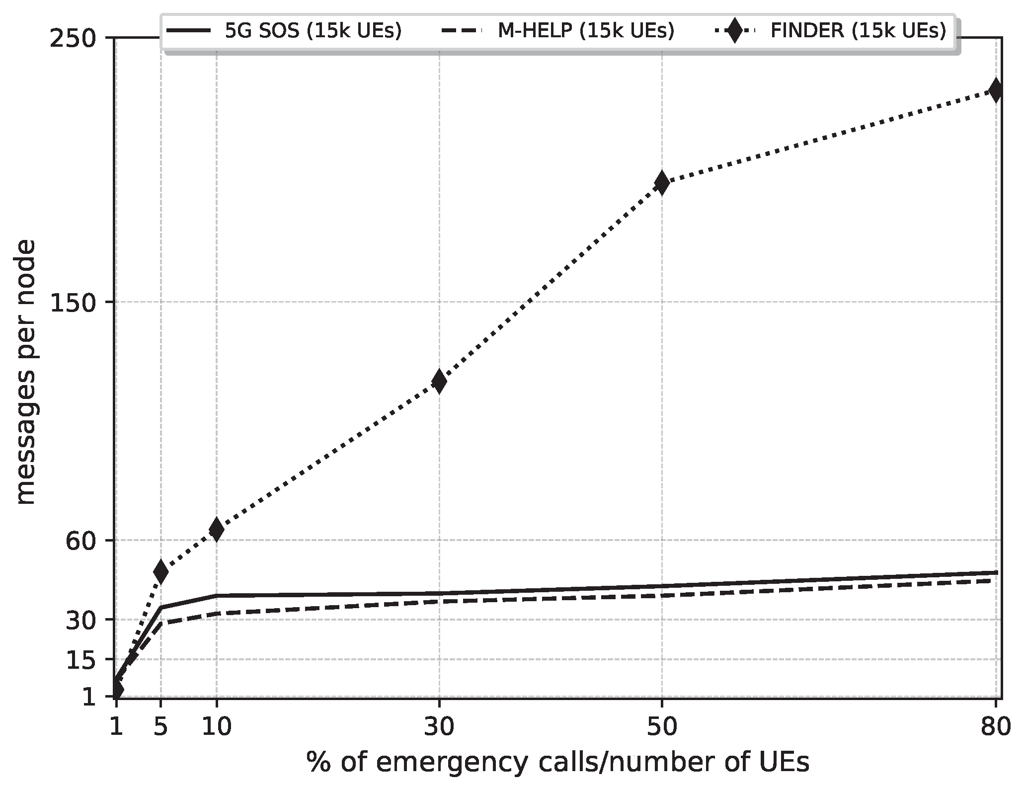
Additionally, as seen in Figure 16, 5G-SOS provides a slightly higher average number of messages per node than M-HELP. The amount of emergency call requests served by 5G-SOS is higher than M-HELP due to buffering multiple calls. Hence, the average number of messages per node has increased against M-HELP. Furthermore, compared to FINDER, 5G-SOS and M-HELP adopt a massively distributed approach where there is no weight on a particular device to relay the emergency call to the gNB. Since the relay devices listen to the transmissions of the same emergency data before transmitting the emergency data on their own, less traffic is generated in the network. Furthermore, the stronger relay devices transfer the message before any other relay device in the neighborhood.
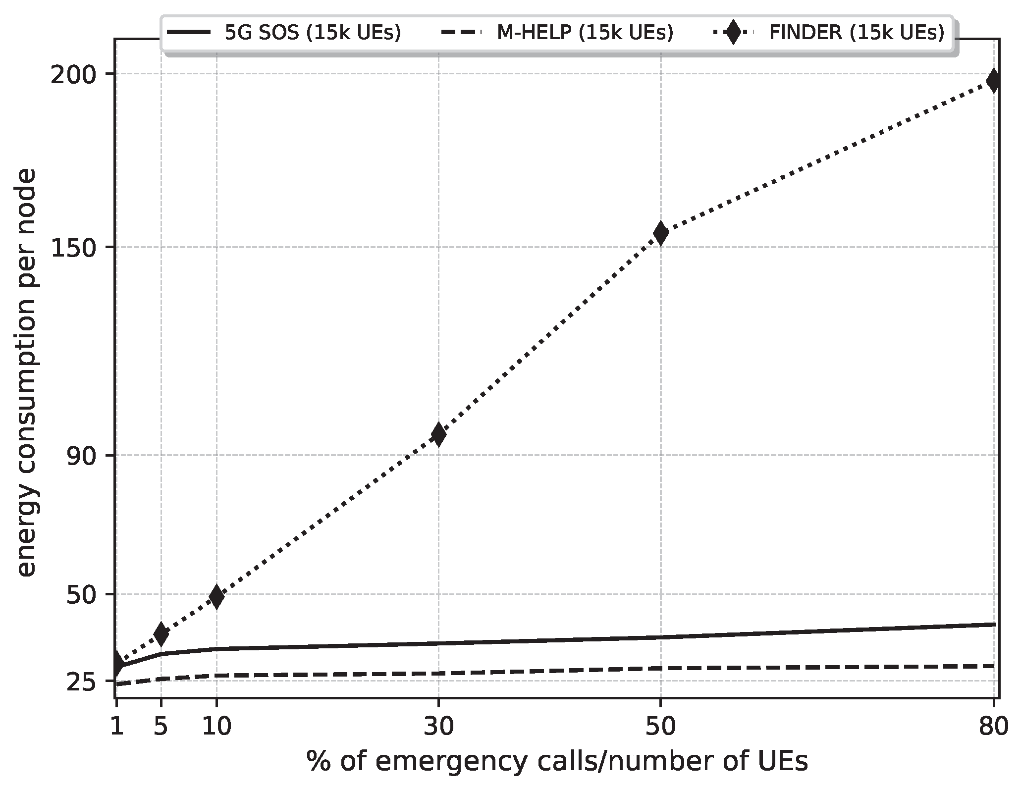
In terms of residual energy, FINDER has a higher energy consumption compared to 5G-SOS and M-HELP, as seen in Figure 17. Furthermore, CHs in FINDER consume higher energy than cluster member devices. Moreover, 5G-SOS consumes a higher energy compared to M-HELP. The 5G-SOS buffers the multiple simultaneous calls received while M-HELP ignores such calls. The computation of the waiting time in (4) offers a dynamic and distributed way to select the stronger relay devices and limit the maximum based on congestion detected in the local neighborhood; this avoids high data congestion at a particular relay device, disperses the traffic among the network devices, and conserves the energy of the intermediate relay devices. Furthermore, the use of the parameter prevents overloading the network with multiple copies of the same requests in a dense environment. Moreover, the lightness of the protocol adding less weight on the relay devices and utilizing the stronger devices to transmit emergency data are the major contributions of 5G-SOS and M-HELP compared to FINDER. All in all, 5G-SOS and M-HELP have improved performance compared to FINDER in terms of transmission success rate, EEL, energy consumption, and network congestion control.
The overall summary of the performance of 5G-SOS over M-HELP and FINDER is given in Table 6. The average improvement by 5G-SOS over all the scenarios considered is approximately 24.9% than M-HELP and 73.9% than FINDER in terms of success rate. Further, the reduction in average end–end latency is 20.8% compared to M-HELP and 61.7% compared to FINDER. Moreover, 5G-SOS enabled a reduction in the average energy consumption by 79.2% compared to FINDER. In contrast, 5G-SOS has a higher energy consumption than M-HELP by around 29.1%. On top of that, the average messages per node in 5G-SOS is lower than FINDER by around 81.3%, but higher than M-HELP by 6.2%.
6. Conclusions
Simulation results using 5G-SOS over Traverse city of Michigan, USA, with a 15,000 population, demonstrated that 5G-SOS succeeds in transfering more than 80% of the emergency calls when the victims represent <5% of the devices. Further, it was observed that 5G-SOS provided a higher success rate, higher average residual energy per node, and lower average number of sent messages per node than FINDER. Moreover, 5G-SOS enhanced M-HELP performance in terms of success rate and end–end latency. In addition, 5G-SOS provided satisfactory performance (success rate of 50%) even when the number of simultaneous emergency calls became very high (5000 calls over 10 min). On average, 5G-SOS performed 24.9% better than M-HELP and 73.9% than FINDER in terms of success rate. Additionally, 5G-SOS reduced the average end–end latency of the emergency calls transfer by 20.8% compared to M-HELP and 61.7% compared to FINDER. The 5G-SOS protocol is characterized by adaptive behavior that uses locally available data provided by sidelink (from neighbors) and downlink (from gNBs) signals. This adaptation allowed adjusting the expected performance of the service (latency and success rate) to the current charge of the network. Limitations of 5G-SOS are having a higher energy consumption than M-HELP by around 29.1% and slightly higher average messages per node than M-HELP by 6.2%. Thereby, designing energy-efficient mechanisms for 5G-SOS-enabled emergency devices is an interesting extension to this work.
Author Contributions
Conceptualization, V.B. and H.M.; original draft preparation, V.B.; supervision, H.M. and D.N.K.J.; co-supervision, P.C. and M.B. All authors have read and agreed to the published version of the manuscript.
Funding
This research was funded by the Fundação para a Ciência e a Tecnologia, Portugal under Grant No.: UIDB/04111/2020 (COPELABS).
Institutional Review Board Statement
Not applicable.
Informed Consent Statement
Not applicable.
Data Availability Statement
The data has been collected using a self-generated simulation model given in https://github.com/Chandrachapa/AM_HELP (accessed on 13 September 2022).
Acknowledgments
This research was funded by the Fundação para a Ciência e a Tecnologia, Portugal under Grant No.: UIDB/04111/2020 (COPELABS).
Conflicts of Interest
The authors declare no conflict of interest.
References
- Usman, R.A.; Olorunfemi, F.; Awotayo, G.; Tunde, A.; Usman, B. Disaster Risk Management and Social Impact Assessment: Understanding Preparedness, Response and Recovery in Community Projects. In Environmental Change and Sustainability; Silvern, S., Young, S., Eds.; IntechOpen: Rijeka, Croatia, 2013; Chapter 10. [Google Scholar] [CrossRef] [Green Version]
- Goshal, S. How 5G Enables Resiliency and Supports a Resolute Society.cdr. 2020. Available online: https://www.tcs.com/content/dam/tcs/pdf/perspectives/covid-19/How-5G-Enables-Resiliency-and-Supports-a-Resolute-Society.pdf (accessed on 1 January 2021).
- Basnayake, V.; Mabed, H.; Canalda, P.; Jayakody, D.N.K. Enhanced Convex Hull based Clustering for High Population Density Avoidance under D2D Enabled Network. In Proceedings of the 2021 IEEE 94th Vehicular Technology Conference (VTC2021-Fall), Norman, OK, USA, 27–30 September 2021; pp. 1–7. [Google Scholar] [CrossRef]
- Carlà, L.; Fantacci, R.; Gei, F.; Marabissi, D.; Micciullo, L. LTE enhancements for Public Safety and Security communications to support Group Multimedia Communications. IEEE Netw. 2015, 30, 80–85. [Google Scholar] [CrossRef] [Green Version]
- Favraud, R.; Apostolaras, A.; Nikaein, N.; Korakis, T. Toward moving public safety networks. IEEE Commun. Mag. 2016, 54, 14–20. [Google Scholar] [CrossRef]
- Doumi, T.; Dolan, M.F.; Tatesh, S.; Casati, A.; Tsirtsis, G.; Anchan, K.; Flore, D. LTE for Public Safety Networks. IEEE Commun. Mag. 2013, 51, 106–112. [Google Scholar] [CrossRef]
- Stavroulakis, P. Terrestrial Trunked Radio—Tetra: A Global Security Tool; Springer Science & Business Media: Berlin, Germany, 2007. [Google Scholar] [CrossRef]
- Ansari, R.I.; Chrysostomou, C.; Hassan, S.A.; Guizani, M.; Mumtaz, S.; Rodriguez, J.; Rodrigues, J.J.P.C. 5G D2D Networks: Techniques, Challenges, and Future Prospects. IEEE Syst. J. 2018, 12, 3970–3984. [Google Scholar] [CrossRef]
- Basnayake, V.; Mabed, H.; Jayakody, D.N.K.; Canalda, P. M-HELP-Multi-Hop Emergency Call Protocol in 5G. In Proceedings of the 2020 IEEE 19th International Symposium on Network Computing and Applications (NCA), Cambridge, MA, USA, 24–27 November 2020; pp. 1–8. [Google Scholar] [CrossRef]
- Thomas, A.; Raja, G. FINDER: A D2D based critical communications framework for disaster management in 5G. Peer-To-Peer Netw. Appl. 2019, 12, 912–923. [Google Scholar] [CrossRef]
- Shang, B.; Zhao, L.; Chen, K.C. Enabling device-to-device communications in LTE-unlicensed spectrum. In Proceedings of the 2017 IEEE International Conference on Communications (ICC), Paris, France, 21–25 May 2017; pp. 1–6. [Google Scholar] [CrossRef]
- Dahlman, E.; Parkvall, S.; Sköld, J. Device-to-Device Connectivity: 4G, LTE Evolution and the Road to 5G; Elsevier: Amsterdam, The Netherlands, 2016; pp. 461–486. [Google Scholar] [CrossRef]
- Sanchoyerto Martinez, A.; Solozabal, R.; Blanco, B.; Liberal, F. Analysis of the impact of the evolution towards 5G architectures on Mission Critical Push-To-Talk services. IEEE Access 2019, 7, 115052–115061. [Google Scholar] [CrossRef]
- 3GPP. Universal Mobile Telecommunications System (UMTS) LTE Proximity-Based Services (ProSe) Stage 2 (3GPP TS 23.303); Technical Specification Version 14.1.0 Release 14 23.303; 3rd Generation Partnership Project (3GPP); European Telecommunications Standards Institute headquarters: Sophia-Antipolis, France, 2017. [Google Scholar]
- Lien, S.; Chien, C.; Liu, G.S.; Tsai, H.; Li, R.; Wang, Y.J. Enhanced LTE Device-to-Device Proximity Services. IEEE Commun. Mag. 2016, 54, 174–182. [Google Scholar] [CrossRef]
- Esposito, C.; Gouglidis, A.; Hutchison, D.; Gurtov, A.; Helvik, B.; Heegaard, P.; Rizzo, G.; Rak, J. On the Disaster Resiliency within the Context of 5G Networks: The RECODIS Experience. In Proceedings of the IEEE European Conference on Networks and Communications 2018, Ljubljana, Slovenia, 18–21 June 2018. [Google Scholar]
- International Telecommunication Union (ITU). ITU-T Focus Group on Disaster Relief Systems, Network Resilience and Recovery; Version 1.0; ITU Publications: Geneva, Switzerland, 2014. [Google Scholar]
- Casoni, M.; Grazia, C.A.; Klapez, M.; Patriciello, N.; Amditis, A.; Sdongos, E. Integration of satellite and LTE for disaster recovery. IEEE Commun. Mag. 2015, 53, 47–53. [Google Scholar] [CrossRef]
- Abdalla, A.; Powell, K.; Marojevic, V.; Geraci, G. UAV-Assisted Attack Prevention, Detection, and Recovery of 5G Networks. IEEE Wirel. Commun. 2020, 27, 40–47. [Google Scholar] [CrossRef]
- Selim, M.Y.; Kamal, A. Post-Disaster 4G/5G Network Rehabilitation Using Drones: Solving Battery and Backhaul Issues. In Proceedings of the 2018 IEEE Globecom Workshops (GC Wkshps), Abu Dhabi, United Arab Emirates, 9–13 December 2018; pp. 1–6. [Google Scholar]
- Kaleem, Z.; Yousaf, M.; Qamar, A.; Ahmad, A.; Duong, T.; Choi, W.; Jamalipour, A. UAV-Empowered Disaster-Resilient Edge Architecture for Delay-Sensitive Communication. IEEE Netw. 2019, 33, 124–132. [Google Scholar] [CrossRef] [Green Version]
- Luo, C.; Miao, W.; Ullah, H.; McClean, S.; Parr, G.; Min, G. Unmanned Aerial Vehicles for Disaster Management. In Geological Disaster Monitoring Based on Sensor Networks; Springer: Singapore, 2019; pp. 83–107. [Google Scholar] [CrossRef]
- Gomez Chavez, K.; Goratti, L.; Rasheed, T.; Reynaud, L. Enabling Disaster Resilient 4G Mobile Communication Networks. IEEE Commun. Mag. 2014, 52, 66–73. [Google Scholar] [CrossRef] [Green Version]
- Globa, L.; Volvach, I. Mobile networks disaster recovery using SDN-NFV. In Proceedings of the Experience of Designing and Application of CAD Systems in Microelectronics, Kiev, Ukraine, 24–27 February 2015; pp. 84–86. [Google Scholar] [CrossRef]
- Malandrino, F.; Chiasserini, C.F.; Landi, G. Towards Failure Resiliency in 5G: Service Shifting. arXiv 2019, arXiv:1902.06317. [Google Scholar]
- Reichman, A.; Wayer, S.I. Ad-hoc network recovery after severe disaster. In Proceedings of the 2019 IEEE International Conference on Microwaves, Antennas, Communications and Electronic Systems (COMCAS), Tel-Aviv, Israel, 4–6 November 2019; pp. 1–3. [Google Scholar]
- Lee, H.; Jeon, D. A mobile ad-hoc network multi-path routing protocol based on biological attractor selection for disaster recovery communication. ICT Express 2015, 1, 86–89. [Google Scholar] [CrossRef]
- Alwan, S.; Fajjari, I.; Aitsaadi, N. D2D Multihop Energy-Efficient Routing and OFDMA Resource Allocation in 5G Networks. In Proceedings of the 2018 IFIP Networking Conference (IFIP Networking) and Workshops, Zurich, Switzerland, 14–16 May 2018; pp. 1–9. [Google Scholar]
- Bastos, A.V.; Silva, C.; Da Silva, D., Jr. Assisted Routing Algorithm for D2D Communication in 5G Wireless Networks. In Proceedings of the 2018 Wireless Days (WD), Dubai, United Arab Emirates, 3–5 April 2018. [Google Scholar] [CrossRef]
- Gutiérrez, D.; Toral, S.; Barrero, F.; Bessis, N.; Asimakopoulou, E. Evaluation of Ad Hoc Networks in Disaster Scenarios. In Proceedings of the 2011 Third International Conference on Intelligent Networking and Collaborative Systems, Fukuoka, Japan, 30 November–2 December 2011; pp. 759–764. [Google Scholar] [CrossRef]
- Menon, V.; Pathrose, J.; Priya, J. Ensuring Reliable Communication in Disaster Recovery Operations with Reliable Routing Technique. Mob. Inf. Syst. 2016, 2016, 1–10. [Google Scholar] [CrossRef] [Green Version]
- Gutiérrez, D.; Askalani, M.; Toral, S.; Barrero, F.; Asimakopoulou, E.; Bessis, N. A Survey on Multihop Ad Hoc Networks for Disaster Response Scenarios. Int. J. Distrib. Sens. Netw. 2015, 11, 647037. [Google Scholar] [CrossRef]
- Singh, A.; Kumar, D.M.; Rishi, R.; Madan, D.K. A relative study of MANET and VANET: Its applications, broadcasting approaches and challenging issues. In Advances in Networks and Communications. CCSIT 2011. Communications in Computer and Information Science; Meghanathan, N., Kaushik, B.K., Nagamalai, D., Eds.; Springer: Berlin/Heidelberg, Germany, 2011; Volume 132, pp. 627–632. [Google Scholar] [CrossRef]
- Anjum, S.; Md. Noor, R.; Anisi, H. Review on MANET Based Communication for Search and Rescue Operations. Wirel. Pers. Commun. 2017, 94, 31–52. [Google Scholar] [CrossRef]
- Afroz, F.; Subramanian, R.; Heidary, R.; Sandrasegaran, K.; Ahmed, S. SINR, RSRP, RSSI and RSRQ Measurements in Long Term Evolution Networks. Int. J. Wirel. Mob. Netw. 2015, 7, 113–123. [Google Scholar] [CrossRef]
- Angri, I.; Najid, A.; Mahfoudi, M. Available bandwidth and RSRP based handover algorithm for LTE/LTE-advanced networks tested in LTE-SIM simulator. Int. J. Electron. Telecommun. 2019, 65, 85–93. [Google Scholar] [CrossRef]
- Shang, F.; Su, W.; Wang, Q.; Gao, H.; Fu, Q. A Location Estimation Algorithm Based on RSSI Vector Similarity Degree. Int. J. Distrib. Sens. Netw. 2014, 2014, 1–22. [Google Scholar] [CrossRef] [Green Version]
- 3GPP. TS 136 214-V14.3.0-LTE; Evolved Universal Terrestrial Radio Access (E-UTRA); Physical Layer; Measurements; 3GPP TS 36.214 Version 14.3.0 Release 14; 3rd Generation Partnership Project (3GPP); European Telecommunications Standards Institute headquarters: Sophia-Antipolis, France, 2017. [Google Scholar]
- Griffith, D.W.; Cintrón, F.J.; Rouil, R.A. Physical Sidelink Control Channel (PSCCH) in Mode 2: Performance analysis. In Proceedings of the 2017 IEEE International Conference on Communications (ICC), Paris, France, 21–25 May 2017; pp. 1–7. [Google Scholar]
- Peckham, S.; Kelbert, A.; Hill, M.; Hutton, E. Towards uncertainty quantification and parameter estimation for Earth system models in a component-based modeling framework. Comput. Geosci. 2016, 90, 152–161. [Google Scholar] [CrossRef]
- Shang, Y.; Qiu, Y. A note on the extended Rosenbrock function. Evol. Comput. 2006, 14, 119–126. [Google Scholar] [CrossRef] [PubMed]
- Katiyar, M. Performance and Sensitivity Analysis of Path Loss Models for WiMAX Signals. In Proceedings of the Conference on Advances in Communication and Control Systems (CAC2S 2013), VA, USA, September 2013; Atlantis Press: Amsterdam, The Netherlands. [Google Scholar] [CrossRef]
Figure 1.
The phases of disaster management cycle during pre-disaster and post-disaster stages.

Figure 2.
Evolution of the 3GPP specifications for missions critical/emergency scenarios using proximity-based services under each release from 11–17.
Figure 2.
Evolution of the 3GPP specifications for missions critical/emergency scenarios using proximity-based services under each release from 11–17.

Figure 3.
The proposed emergency call service architecture. Emergency UEs in the disaster area forward their calls in the direction of the functioning gNBs via relay UEs in the neighborhood. Distinct emergency calls generated by each emergency UE are represented by the color of the arrow. Solid lines indicate the D2D communication mode, while dashed lines indicate the classical communication between gNB and UE.

Figure 4.
Illustration of the standard Rosenbrock function defined by two variables and given by . Here, we assume a = 1, b = 100, and the minimum value of zero is at (1,1). The adaptive given in (5) is based on the Rosenbrock function.
Figure 4.
Illustration of the standard Rosenbrock function defined by two variables and given by . Here, we assume a = 1, b = 100, and the minimum value of zero is at (1,1). The adaptive given in (5) is based on the Rosenbrock function.

Figure 5.
A relay UE gives higher priority for a far emergency UE than a near UE using the RSSI ratio. The RSSI ratio in (4) is lower for a far UE than a near UE. The relay UE waits a lesser time, hence relays faster the transmissions of the far UE emergency call in the direction of a functioning gNB.

Figure 6.
Studied scenario of the Traverse city in Michigan, USA, with 7 gNBs and 15,000 randomly distributed UEs in the AnyLogic® software. Linked UEs (resp. UE-to-gNB links) represent D2D (resp. traditional) communication possibilities. Dark Red circles represent the gNBs’ covering areas in which the gNBs are at the center. Victim (emergency) devices, relay devices, in-coverage devices, and idle devices are represented respectively by the colors, red, green, yellow, and blue.

Figure 7.
Variation of under three ranges of . (a) Variation of against and , when the observed in the neighborhood is between 0 and 10. (b) Variation of against and , when the observed in the neighborhood is between 10 and 200. (c) Variation of against and , when the observed in the neighborhood is above 200.

Figure 8.
Comparison of successful rate against emergency time interval (ETI) under 5G-SOS, M-HELP, and FINDER. Parameters: ETI: 600–1800 s, NoU: 15,000, NEC: 5000.
Figure 8.
Comparison of successful rate against emergency time interval (ETI) under 5G-SOS, M-HELP, and FINDER. Parameters: ETI: 600–1800 s, NoU: 15,000, NEC: 5000.

Figure 9.
Comparison of end–end latency against ETI under 5G-SOS, M-HELP, and FINDER. Parameters: ETI: 600–1800 s, NoU: 15,000, NEC: 5000.
Figure 9.
Comparison of end–end latency against ETI under 5G-SOS, M-HELP, and FINDER. Parameters: ETI: 600–1800 s, NoU: 15,000, NEC: 5000.

Figure 10.
Comparison of successful rate against number of UEs (NoU) under 5G-SOS, M-HELP, and FINDER. Parameters: NoU: 6000 to 15,000, NEC: 5000, ETI: 1800 s (30 min).
Figure 10.
Comparison of successful rate against number of UEs (NoU) under 5G-SOS, M-HELP, and FINDER. Parameters: NoU: 6000 to 15,000, NEC: 5000, ETI: 1800 s (30 min).

Figure 11.
Comparison of end–end latency against NoU under 5G-SOS, M-HELP, and FINDER. Parameters: NoU: 6000 to 15,000, NEC: 5000, ETI: 1800 s (30 min).
Figure 11.
Comparison of end–end latency against NoU under 5G-SOS, M-HELP, and FINDER. Parameters: NoU: 6000 to 15,000, NEC: 5000, ETI: 1800 s (30 min).

Figure 12.
Comparison of successful rate against emergency call transfer duration under 5G-SOS, M-HELP, and FINDER. Parameters: NoU: 15,000, NEC: 5000, ETI: 1800 s (30 min).
Figure 12.
Comparison of successful rate against emergency call transfer duration under 5G-SOS, M-HELP, and FINDER. Parameters: NoU: 15,000, NEC: 5000, ETI: 1800 s (30 min).

Figure 13.
Comparison of end–end latency against emergency call transfer duration under 5G-SOS, M-HELP, and FINDER. Parameters: NoU: 15,000, NEC: 5000, ETI: 1800 s (30 min).
Figure 13.
Comparison of end–end latency against emergency call transfer duration under 5G-SOS, M-HELP, and FINDER. Parameters: NoU: 15,000, NEC: 5000, ETI: 1800 s (30 min).

Figure 14.
Comparison of the success rate against the ratio of the number of emergency calls (NEC) to the number of UEs (NoU) under 5G-SOS, M-HELP, and FINDER. Parameters: NoU: NEC: 1% of NoU to 80% of NoU, NoU: 15,000 UEs, ETI: 1800 s (30 min).
Figure 14.
Comparison of the success rate against the ratio of the number of emergency calls (NEC) to the number of UEs (NoU) under 5G-SOS, M-HELP, and FINDER. Parameters: NoU: NEC: 1% of NoU to 80% of NoU, NoU: 15,000 UEs, ETI: 1800 s (30 min).

Figure 15.
Comparison of end–end latency against the ratio of the number of emergency calls (NEC) to the number of UEs (NoU) under 5G-SOS, M-HELP, and FINDER. Parameters: NEC: 1% of NoU to 80% of NoU, NoU: 15,000 UEs, ETI: 1800 s (30 min).
Figure 15.
Comparison of end–end latency against the ratio of the number of emergency calls (NEC) to the number of UEs (NoU) under 5G-SOS, M-HELP, and FINDER. Parameters: NEC: 1% of NoU to 80% of NoU, NoU: 15,000 UEs, ETI: 1800 s (30 min).

Figure 16.
Comparison of the number of messages per node against the ratio of the number of emergency calls (NEC) to the number of UEs (NoU) under 5G-SOS, M-HELP, and FINDER. Parameters: NoU: NEC: 1% of NoU to 80% of NoU, NoU: 15,000 UEs, ETI: 1800 s (30 min).
Figure 16.
Comparison of the number of messages per node against the ratio of the number of emergency calls (NEC) to the number of UEs (NoU) under 5G-SOS, M-HELP, and FINDER. Parameters: NoU: NEC: 1% of NoU to 80% of NoU, NoU: 15,000 UEs, ETI: 1800 s (30 min).

Figure 17.
Comparison of the energy consumption per node against the ratio of the number of emergency calls (NEC) to the number of UEs (NoU) under 5G-SOS, M-HELP, and FINDER. Parameters: NoU: NEC: 1% of NoU to 80% of NoU, NoU: 15,000 UEs, ETI: 1800 s (30 min).
Figure 17.
Comparison of the energy consumption per node against the ratio of the number of emergency calls (NEC) to the number of UEs (NoU) under 5G-SOS, M-HELP, and FINDER. Parameters: NoU: NEC: 1% of NoU to 80% of NoU, NoU: 15,000 UEs, ETI: 1800 s (30 min).


Table 1.
Existing works in the literature on wireless network recovery.
| Related Work | External Architecture | Resilient Architecture | Resilient Application | Resilient Protocol | 3GPP Compatible | Out-of-Coverage |
|---|---|---|---|---|---|---|
| UAV-Assisted Attack Prevention, Detection, and Recovery of 5G Networks [19] | x | x | ||||
| Post-Disaster 4G/5G Network Rehabilitation Using Drones: Solving Battery and Backhaul Issues [20] | x | x | ||||
| Integration of satellite and LTE for disaster recovery [18] | x | x | ||||
| UAV-Empowered Disaster-Resilient Edge Architecture for Delay-Sensitive Communication [21] | x | x | ||||
| On the Disaster Resiliency within the Context of 5G Networks: The RECODIS Experience [16] | x | x | ||||
| Enabling Disaster Resilient 4G Mobile Communication Networks [23] | x | x | ||||
| Terrestrial Trunked Radio-Tetra: A Global Security Tool [24] | x | x | ||||
| Towards Failure Resiliency in 5G: Service Shifting [25] | x | x | ||||
| Ad-hoc network recovery after severe disaster [26] | x | x | ||||
| A mobile ad-hoc network multi-path routing protocol based on biological attractor selection for disaster recovery communication [27] | x | x | ||||
| D2D Multihop Energy-Efficient Routing and OFDMA Resource Allocation in 5G Networks [28] | x | x | ||||
| Assisted Routing Algorithm for D2D Communication in 5G Wireless Networks [29] | x | x | ||||
| FINDER: A D2D based critical communications framework for disaster management in 5G [10] | x | x | x | |||
| M-HELP-Multi-Hop Emergency Call Protocol in 5G [9] | x | x | x |
Table 2.
Notations used in Algorithms 1–3.
| Notation | Description |
|---|---|
| FIFO list of calls in the buffer to be relayed | |
| List of calls already received and processed in the past | |
| DATA | Emergency call |
| srcID | Identifier of the source device |
| callID | Identifier of the emergency call |
| callIDGenerator | Function used by each UE to generate unique call IDs |
| waitingCall | A call stored in |
| deadline | latest time by which a waitingCall is transmitted |
| nbAttempts | Count that DATA was trasnmitted or relayed |
| relay | relay device information content in DATA |
Table 3.
Expected behavior of with and .
| ↓ | ↓ | ↓ |
| ↓ | ↑ | ↑ |
| ↑ | ↑ | ↓ |
Table 4.
Adaptive model parameters.
| Limits | a | b |
|---|---|---|
| 1 | 0.5 | |
| 1 | 0.2 | |
| 1 | 0.1 |
Table 5.
Traverse city area emergency simulation parameters.
| Parameter | Value |
|---|---|
| Total network area | 16.2 × |
| Amount of working gNBs | 7 |
| Total UE spread | RAND (16.2,21) |
| Initial | 120 s |
| Initial | 120 s |
| UE’s GPS localization accuracy | RAND (0.001,1) |
| Initial UE’s SoC | RAND (0,100) J |
| BS/gNB Link distance (d) | 1.5 km |
| D2D link connection range | 1.5 km |
| Data transfer delay by D2D mode, | 10 s |
| Data transfer delay by classical PUSCH mode | 1 s |
| Maximum limit for , | 5 |
| Upper bound of waiting time, | 120 s |
| Upper limit of re-transmissions, | 4 |
| Maximum number of messages in | 3 |
| Transmit power of gNB, () | 300.0 dBm |
| Signal transmission frequency of gNBs (f) | 885 MHz |
| BS/gNB antenna effective height () | 100 m |
| UE antenna effective height () | 1.5 m |
| Constant offset of Cost231 Hata model () | 0 dB |
| Number of UEs, NoU | variable |
| Number of emergency calls, NEC | variable |
| Emergency calls occurring interval, ETI | variable |
| Energy to transmit | 0.08 mJ [10] |
| Energy to receive | 0.05 mJ [10] |
| Total Simulation running time | 30 min |
Table 6.
Summary of performance analysis.
| Parameter | Gain in 5G-SOS vs. M-HELP | Gain in 5G-SOS vs. FINDER | Comparison |
|---|---|---|---|
| Success rate | > | ||
| > | |||
| << | |||
| << | |||
| << |
Publisher’s Note: MDPI stays neutral with regard to jurisdictional claims in published maps and institutional affiliations. |
© 2022 by the authors. Licensee MDPI, Basel, Switzerland. This article is an open access article distributed under the terms and conditions of the Creative Commons Attribution (CC BY) license (https://creativecommons.org/licenses/by/4.0/).
Share and Cite
MDPI and ACS Style
Basnayake, V.; Mabed, H.; Jayakody, D.N.K.; Canalda, P.; Beko, M. Adaptive Emergency Call Service for Disaster Management. J. Sens. Actuator Netw. 2022, 11, 83. https://doi.org/10.3390/jsan11040083
AMA Style
Basnayake V, Mabed H, Jayakody DNK, Canalda P, Beko M. Adaptive Emergency Call Service for Disaster Management. Journal of Sensor and Actuator Networks. 2022; 11(4):83. https://doi.org/10.3390/jsan11040083
Chicago/Turabian StyleBasnayake, Vishaka, Hakim Mabed, Dushantha Nalin K. Jayakody, Philippe Canalda, and Marko Beko. 2022. "Adaptive Emergency Call Service for Disaster Management" Journal of Sensor and Actuator Networks 11, no. 4: 83. https://doi.org/10.3390/jsan11040083
Note that from the first issue of 2016, this journal uses article numbers instead of page numbers. See further details here.