Article

Microstructure Evolution and Hardness Improvement of WC-Co Composites Sintered with Fe Substituting Part of Co Binder

1
Key Laboratory for Anisotropy and Texture of Materials, Ministry of Education, Northeastern University, Shenyang 110819, China
2
Liaoning Wuhuan Special Materials and Intelligent Equipment Industry Technology Research Institute Co., Ltd., Shenyang 113122, China
3
Institut de Chimie Moléculaire et Des Matériaux d’Orsay, Université Paris-Saclay, 91405 Orsay, France
*
Author to whom correspondence should be addressed.
Coatings 2023, 13(1), 116; https://doi.org/10.3390/coatings13010116
Submission received: 7 December 2022 / Revised: 21 December 2022 / Accepted: 4 January 2023 / Published: 8 January 2023
(This article belongs to the Special Issue Ceramic Films and Coatings: Properties and Applications)

Abstract

:
WC-13Co (wt.%) composite with Fe added was prepared by pressureless sintering, and its microstructure and mechanical properties were analyzed by X-ray Diffraction (XRD), Scanning Electronic Microscopy (SEM), Energy Dispersive Spectroscopy (EDS) and Vickers hardness tester. The effect of Fe and C content on the microstructure of the eta phase, binder phase, grain size and porosity, as well as mechanical properties in the W-Co-Fe-C system, was discussed quantitatively. The position of added Fe in the lattice of the composites is clarified. When 2%–4% Fe was added, Fe existes in both the binder phase and the low-carbon eta phase. In the lattice of the eta phase, Fe occupies the position of Co and Fe uniformly existes in the binder with the structure of simple cubic when the composites is in the eutectic phase region. Differently from the previous report that the growth of WC in liquid Fe was severely limited, the size of WC in the W-Co-Fe-C system increases from 1.14 μm to 1.21 μm when the content of Fe increases from 0 to 4%, which indicates that the growth behavior of WC in liquid CoFe was different from that in liquid Fe, but closer to that in liquid Co. The sample added both 2% Fe and 1% C has the optimum matching of hardness and toughness. Compared with the hardness of 979 HV30 in the sample without adding Fe and C, the hardness of the sample with both 2% Fe and 1% C added achieved 1071 HV30, which is increased by 9.4% under the conditions of a slight increase in fracture toughness.

1. Introduction

Composites can obtain comprehensive properties that cannot be achieved by the single component material [1,2,3,4], and they are an important achievement of material technology during the development of human civilization. More than 100 years ago, in order to replace expensive diamonds, the WC-Co composite, which was composed of hard WC particles and tough Co binder, was invented by powder sintering in the cutting processing industry [5]. At present, this material has been widely used in wear-resistant parts and the cutting tools of mining, machinery, oil mining, aerospace and other industries [6]. For each country, Co is a limited resources and is widely used not only in WC-Co composites as binders [7], but also in other important alloys, such as ultra-high strength martensitic steel for aircraft landing gear [8], high-performance Co-based soft magnetic materials [9], and high efficiency lithium batteries for new energy vehicles, which have developed rapidly in recent years [10]. Therefore, researchers have been considering new alternative binders for many years. In particular, the new European chemicals regulation clearly proposes to consider partially replacing Co with Fe and Ni [11]. Both Fe and Ni are transition metals close to Co element in the periodic table and have similar affinity with carbon and tungsten.
The replacement of Co with Fe and Ni has been a research focus of WC-Co composites. Uhrenius’ [12] work showed that the calculated phase diagram based on Thermo Calc databases can be used to predict the corresponding C content in the two-phase region WC + fcc (face-centered cubic) under different Fe, Ni and Co content combinations in the new Fe-Ni-Co-W-C composites. Shon et al. [13] fabricated the WC-10Co (wt.%), WC-10Ni and WC-10Fe composites by the high-frequency induction heating sintering (HFIHS) method and further discussed the effects of Fe and Ni on sintering behavior, density, grain size and mechanical properties of the composites. Soria-Bairrun et al. [14] added Cr to the binder of WC-Co-Fe-Ni composite, and found that, compared with the phase diagram of WC-FeNiCo based on Thermocalc, the position of the carbon window and the temperature of solidus and liquidus are significantly affected by the content of Cr.
After replacing Co with other metal elements, the microstructure evolution changed significantly in WC-based composites. Marek Tarraste et al. [15] fabricated the WC-FeCr composites using ferrite chromium steel as the binder metal and found that the addition of about 2% carbon in WC-30%FeCr composites can hinder the formation of the eta phase. Wittmann [16] investigated the effect of VC and other inhibitors on the growth of WC grains when Ni and Fe are used as binders and found that VC is the most effective grain growth inhibitor in WC-Ni hard metals, while the growth of WC grains is strongly restricted even if no growth inhibitor is added in Fe-binder composites.
Furthermore, it is possible to obtain higher mechanical properties and corrosion resistance through the replacement of reasonable content of Fe and Ni [17]. Kakeshita et al. [18] found that the toughness of WC-(Fe-Ni-C) composites is higher than that of common WC-Co composite by controlling martensitic transformation strengthening. Guo et al. [19] investigated the influence of heat treatment on the toughness of WC-(Fe-Ni-C) composites, and results showed that isothermal heat treatment can also effectively improve the toughness. Chang et al. [20] reported that, compared with WC-Co composites, the sintered nanostructured WC-(Co-Ni-Fe) composites have better corrosion resistance and mechanical properties.
The efforts above have shown that Fe has become an important alloying element to replace Co in WC-Co-based composites. On the other hand, completely replacing Co with Fe or Ni leads to a sharp decline in the performance of composites, and the composites showed an extremely narrow carbon window (about 40% of WC-Co composites) at binder contents of ≤10 wt.%, resulting in difficult control of the stability and reliability of products in the factory.
At present, the research on WC-Co composites with added Fe has paid more attention to the calculated phase diagram, WC grain growth, mechanical properties and corrosion resistance. The research on the composition and distribution of the eta phase as well as the occupation of Fe atoms in the lattice of WC-Co composites adding Fe is still limited. Moreover, although the current experimental work has illustrated a good agreement with the calculated phase diagram of WC-Co containing Fe based on CALPHAD, more experimental data are needed, especially on the eta phase formation side, to better compare the experimental and calculation [21].
In this work, WC-Co-based composites with different Fe contents were prepared by powder metallurgy. The key factors affecting the mechanical properties, such as the density, eta phase and WC grain size, as well as the composition and structure of the binders, were studied. The occupation of Fe atoms in the crystallographic lattice of the composites after the addition of Fe powder was also explored.

2. Experimental Procedure

Commercial tungsten carbide powder (6.1% C, W ≥ 93.72, p ≤ 0.001%, S ≤ 0.001%, 0.094% O, others ≤ 0.001%, wt.%, average particle size of 2 μm, Xiamen golden egret special alloy Co., Ltd., Xiamen, China, Figure 1a), Co powder (Co ≥ 99.9%, Mn ≤ 0.0001%, Cu ≤ 0.0003%, others ≤ 0.005%, average particle size of 0.8 μm, 99.9 wt.% purity, Xiamen golden egret special alloy Co., Ltd., Xiamen, China, Figure 1b), Fe powder (Fe ≥ 99.0%, average particle size of 10 μm, Qinghe county Kegong Metallurgical Materials Co., Ltd., Xingtai, China, Figure 1c), W powder (W ≥ 99.0%, average particle size of 1.2 μm, Xiamen golden egret special alloy Co., Ltd., Xiamen, China, Figure 1d) and carbon black (average particle size of 200 nm, Xiamen golden egret special alloy Co., Ltd., Xiamen, China) were selected as raw materials. Table 1 shows the nominal chemical compositions of different WC-Co composites. The carbon content is calculated as follows: Ct% = (C1 + C2)/Mt, where Ct% is the weight of total carbon in the sample, C1 is the weight of carbon in WC powder, C2 is the weight of adding carbon black, and Mt is the total weight of sample. The Ct is important for evaluating the carbon content in the sample, although it ignores the carbon loss during the sintering process.
Various weighed powders and ethanol were put into the ball mill. The weight ratio of the ball to powder was 4:1, and the ball milling lasted for 24 h. Then, the mixed materials were placed in a 70 °C vacuum drying furnace, and the drying time was 5 h. After drying, the powder was sieved with an 80 mesh sieve and pressed into a mold with a diameter of 20 mm under the pressure of 240 Mpa. Finally, the pressed blank was heated in a tubular experimental furnace (GSL-1700X, Hefei Kejing Co., Ltd., Hefei, China) from room temperature to 1000 °C at the rate of 10 °C/min, then heated to 1430 °C at the rate of 5 °C/min, kept at 1430 °C for 1 h, and then cooled in the furnace. The atmosphere for oxidation prevention was argon during sintering.
The prepared samples were ground and polished to analyze the phase by XRD-7000 (Shimadzu Co., Ltd., Kyoto, Japan, Cu target.). The selected angle was 20°–80° and the scanning speed was 5°/min. Quanta 250FEG SEM (FEI Co., Ltd., Hillsboro, OR, USA) equipped with energy dispersive spectroscopy (EDS) was used to analyze the microstructure and chemical element distribution. Image Pro Plus image analysis software was used to measure WC grain size. After sintering, the electronic analytical scale (JHY-600Q, Xiamen Jinheyuan Technology Co., Ltd., Xiamen, China) was used to measure the bulk density, which is calculated using the Archimedes principle. The pressure of the indenter for measuring Vickers hardness was 30 kg, lasting for 10 s. Moreover, in view of the high toughness of the samples 0Fe-5.3C and 2Fe-6.3C, the hardness tests at 50 kg pressure and 10 s were carried out on the two samples in order to observe the crack morphology.

3. Results and Discussion

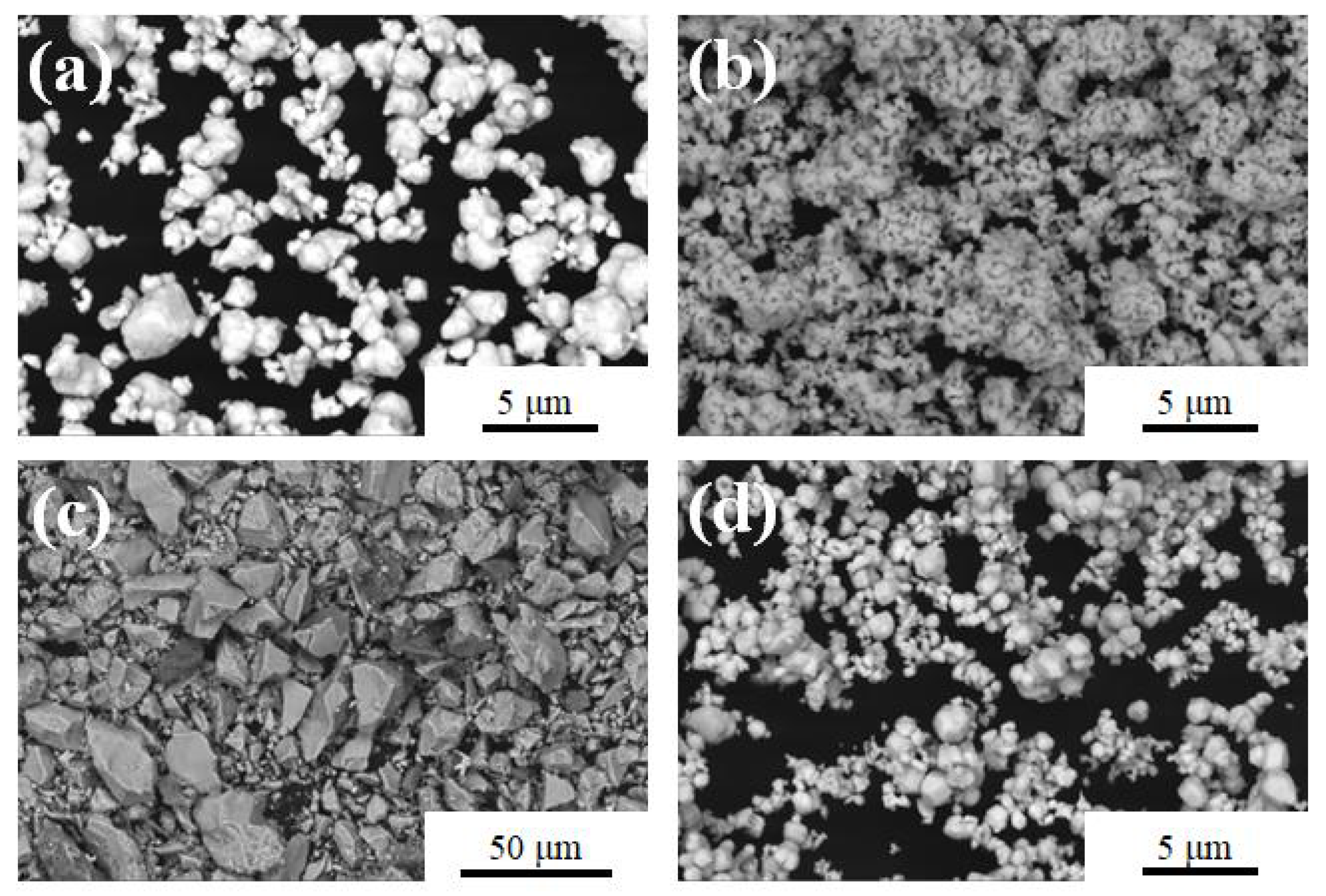
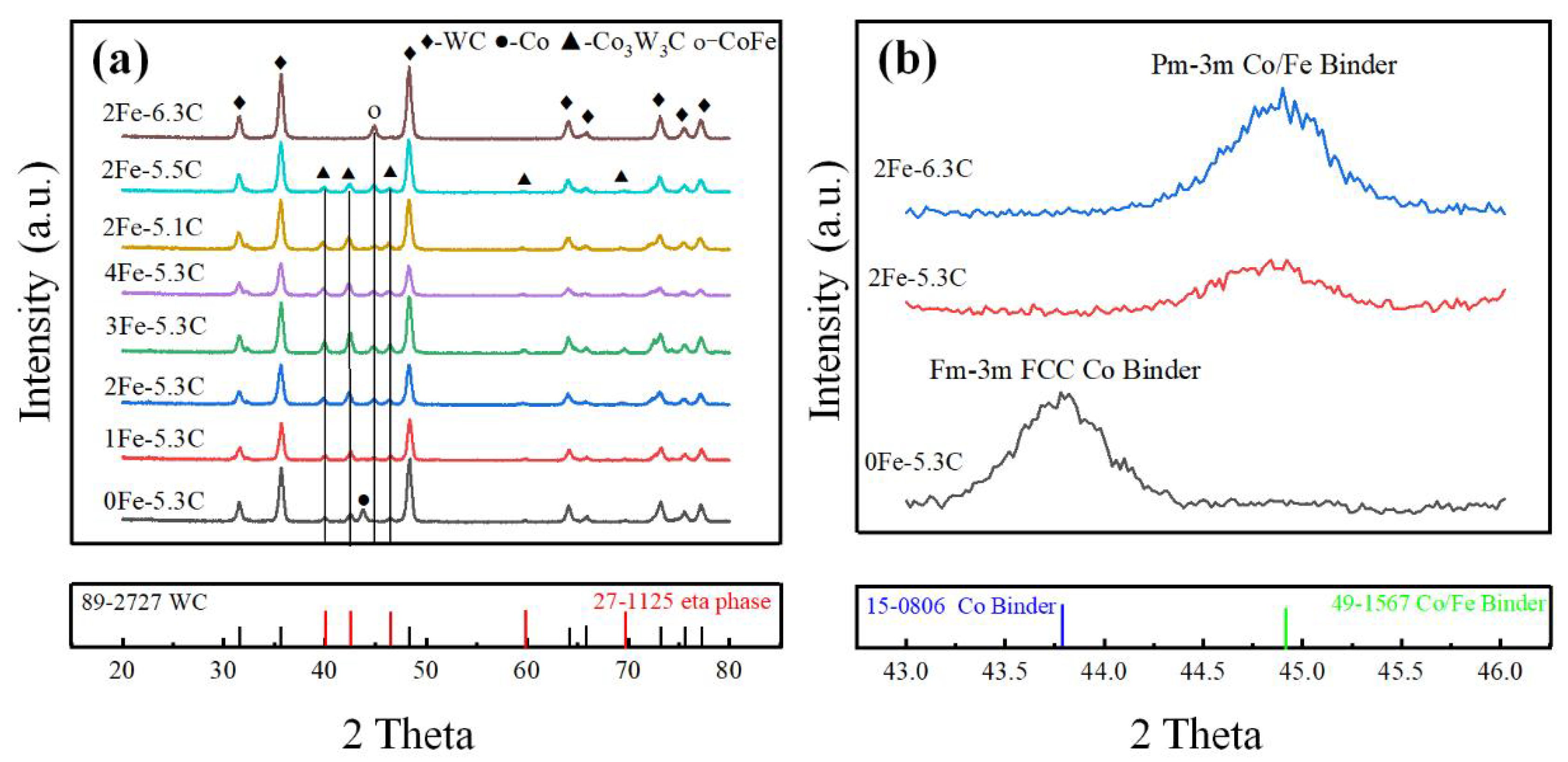
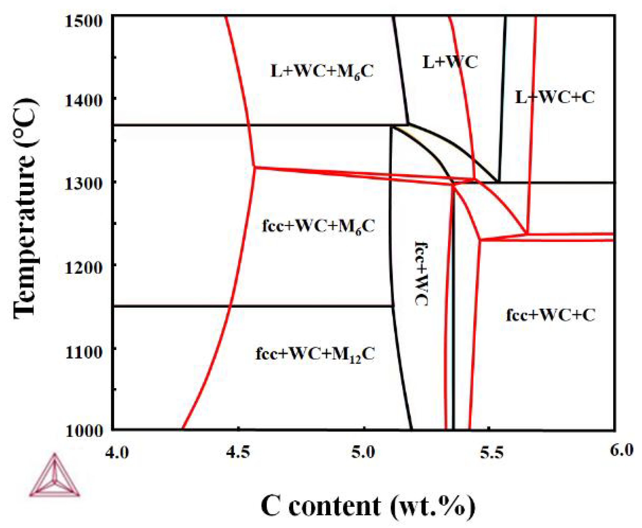
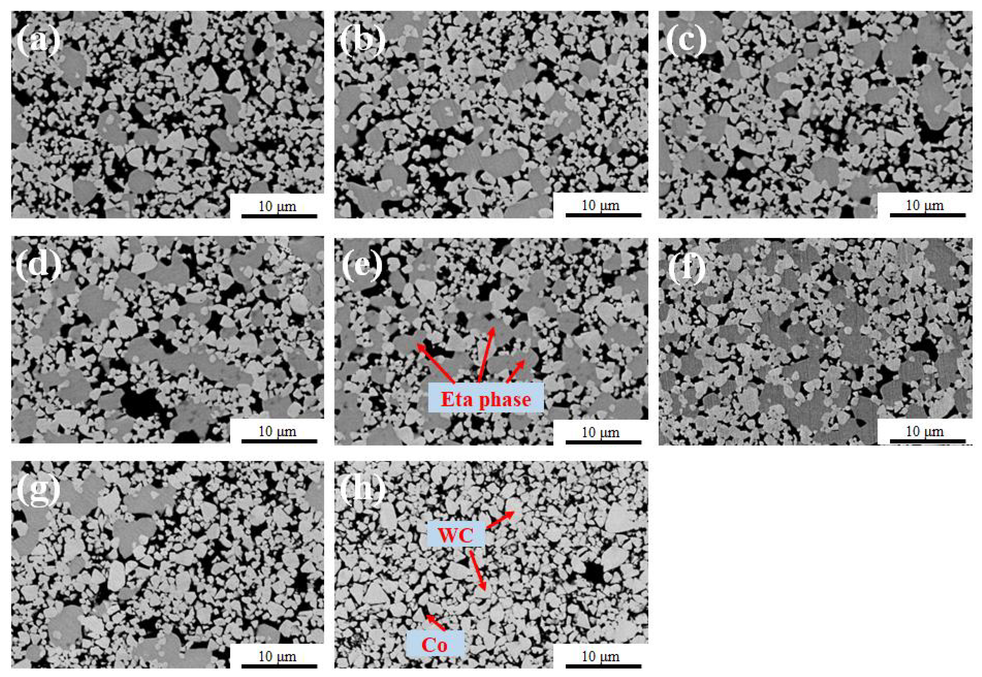
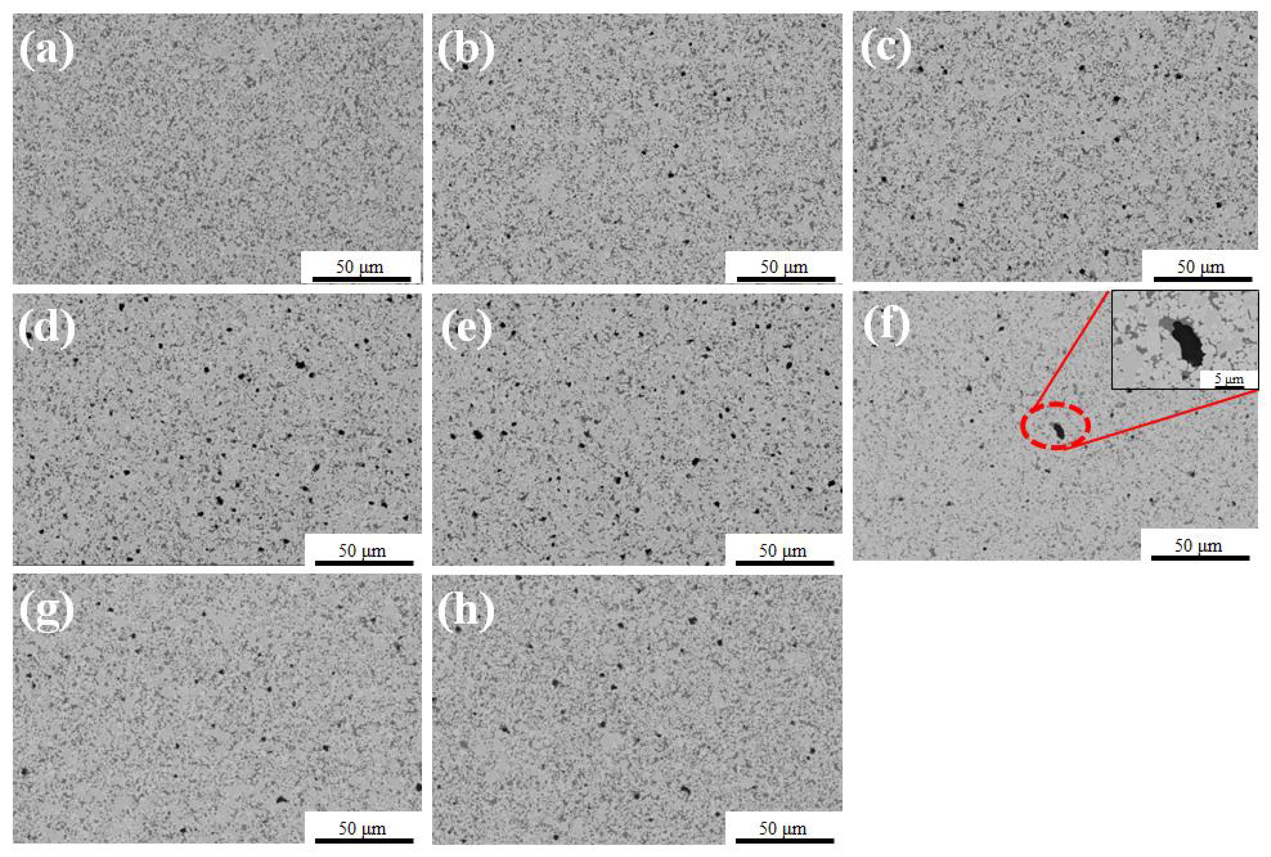
3.1. The Microstructure of WC-Co-Fe Composites

The XRD patterns of different samples are illustrated in Figure 2, and the composites of 0Fe-5.3C, 1Fe-5.3C, 2Fe-5.3C, 3Fe-5.3C, 4Fe-5.3C, 2Fe-5.1C and 2Fe-5.5C are composed of three phases: WC, binder and eta phase. Only binder phase and WC exist in samples 2Fe-6.3C. Moreover, with the increase of Fe content, the peak value of the eta phase increases, indicating that the formation of eta phase is promoted by replacing Co with Fe. In the environment of low-carbon content, the reaction between WC and Co contributes to the formation of the eta phase, which is usually called M6C and M12C [22] (or Co3W3C and Co6W6C [23]). The addition of C leads to the disappearance of the eta phase in the 2Fe-6.3C sample.
Furthermore, the crystal structure of the binder phase changes with the addition of Fe and C. The binder phase in the 0Fe-5.3C sample is Co-binder, corresponding to the lattice constant of 3.57. After 2%–4% Fe is added, the CoFe-binder is formed, corresponding to the lattice constants of 2.82. Through adding 1% C in the 2Fe-6.3C sample, the eta phase is eliminated and the sample is a two-phase material, consisting of B2 ordered (simple cubic, sc) CoFe and WC, and the Co-binder phase of fcc cannot be observed. In addition, the content of added Fe has no obvious effect on the lattice constant of the eta phase. The lattice constant of the eta phase is about 11.04 in all samples of 0Fe-5.3C, 1Fe-5.3C, 2Fe-5.3C, 3Fe-5.3C, 4Fe-5.3C, 2Fe-5.1C and 2Fe-5.5C. The occupation of Fe in the lattice of the eta phase of WC-Co composites has been reported [24], and the results of this study are in agreement with it, and it is difficult to observe the change of the corresponding 2θ angle in the XRD pattern due to the very similar atomic radii of Fe and Co (Fe: 1.27 Å, Co: 1.26 Å).
As mentioned above, there are more eta phases in the sample added with Fe, which indicates that Fe promotes the expansion of the upper limit of C in the fcc + WC + eta phase region. Figure 3 demonstrates the phase diagram of WC-13Co and WC-9Co-4Fe calculated by Thermo-Calc software. It can be seen that, with the increase of Fe, the carbon content range of the WC + fcc two-phase region increases from 5.19%–5.36% to 5.33%–5.42%; that is, the addition of Fe expands the range of carbon content in the phase diagram corresponding to the WC + fcc two-phase region in the WC-Co-Fe system. It should be pointed out that there is a large carbon loss in the sintering process, as reported by [25,26], so the nominal C content in Table 1 is significantly higher than the carbon content in the phase diagram in Figure 3.
The eta phase can be clearly observed in the BSE-SEM images in Figure 4. With the addition of Fe from 0 to 4.0%, the area fraction and the size of the eta phase increase sharply. In the 0Fe-5.3C sample, the eta phase size is relatively small, and most eta phases are slightly larger than WC grains and, moreover, in the samples adding 4% Fe, the size of some eta phases reache ~10 μm, which is more than five times the WC size. With the increase of carbon black in the sample adding of 2% Fe, the fraction of the eta phase gradually decreases and it finally disappears in the sample of 2Fe-6.3C.
Figure 5 further illustrates the statistical area fraction of the eta phase. The eta phase is very sensitive to the addition of Fe. Under the same carbon content conditions, when 4% Fe was used to replace 4% Co, the proportion of the eta phase increased more than twice, from 20% to 45.3%. When the added content of C reached 1%, the proportion of the eta phase decreased to 0% in the sample of 2% Fe. Carbon black effectively inhibits the formation of the eta phase in the 2Fe-6.3C sample. Wei et al. [27] also eliminated the eta phase by adding carbon when using the WO2, Co3O4 and C as raw materials to manufacture WC-Co composites.
The eta phase and Co in the 2Fe-5.3C sample are further analyzed by EDS as exhibited in Figure 6 and Figure 7. In addition to replacing Co in the binder (Figure 6a), the added Fe also exists in the eta phase (Figure 6b) in 2Fe-5.3C sample, while in the 2Fe-6.3C sample, Fe only exists in the binder (Figure 6c) due to the disappeared eta phase, as shown in Figure 2 and Figure 5. Moreover, the Co content in the binder and eta phases of the 2Fe-5.3C sample is higher than the Fe content, as seen in Figure 7.
To sum up, for the sample without an eta phase such as 2Fe-6.3C, Fe mainly exists in the binder, forming a solid solution with B2 ordered structure (Figure 2). When the WC-13 (Co-Fe) composite is sintered at low-carbon content, such as 1Fe-5.3C, 2Fe-5.3C, 3Fe-5.3C, 4Fe-5.3C, 2Fe-5.1C and 2Fe-5.5C, Fe exists in both the eta phase and B2 ordered binder, which has been confirmed by EDS analysis in Figure 6. In the eta phase, Fe occupies the Co position instead of the W position, which can be identified by comparing the diffraction peaks of the eta phase of 0Fe-5.3C and 2Fe-5.3C samples in Figure 2. If Fe occupies the W position, the lattice constant will be greatly changed due to the large difference between the atomic radii of Fe and W. Figure 8 demonstrates the schematic diagram of atomic occupancy of Fe in the lattice of WC-13 (Co-Fe) composites.
Figure 9 illustrates the distribution of the grain size of the composites. With the Fe content increase from 0 to 4% (Figure 9a–e), the grain size of WC increases slightly from 1.14 μm to 1.21 μm, which is different from the previous report that the growth of WC was hindered by adding Fe [16]. The growth of the WC grains was primarily related to the dissolution and re-precipitation of WC grains in the binder phase during liquid phase sintering [28]. Roulon et al. [11] found that the solubility of WC in liquid Fe is lower than that in liquid Co. Wittmann et al. [16] reported that the substitution of Fe for Co as a binder would strongly limit the growth of WC grains during liquid sintering.
The results in Figure 9 demonstrate that the growth behavior of WC in liquid CoFe is close to that of liquid Co but completely different from that of liquid Fe. Moreover, with the increase of the content of carbon added, the grain size of the composites further increased from 1.21 μm to 1.42 μm. Konyashin et al. [29] pointed out that the high-carbon environment is more conducive to the WC coarsening in WC-Co hard metals, although the influence of carbon content on the grain growth behavior in the W-C-Co-Fe system is still unclear.

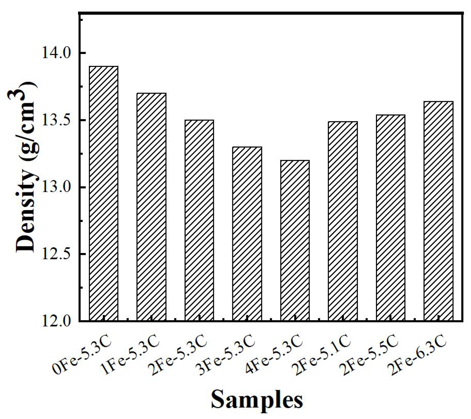
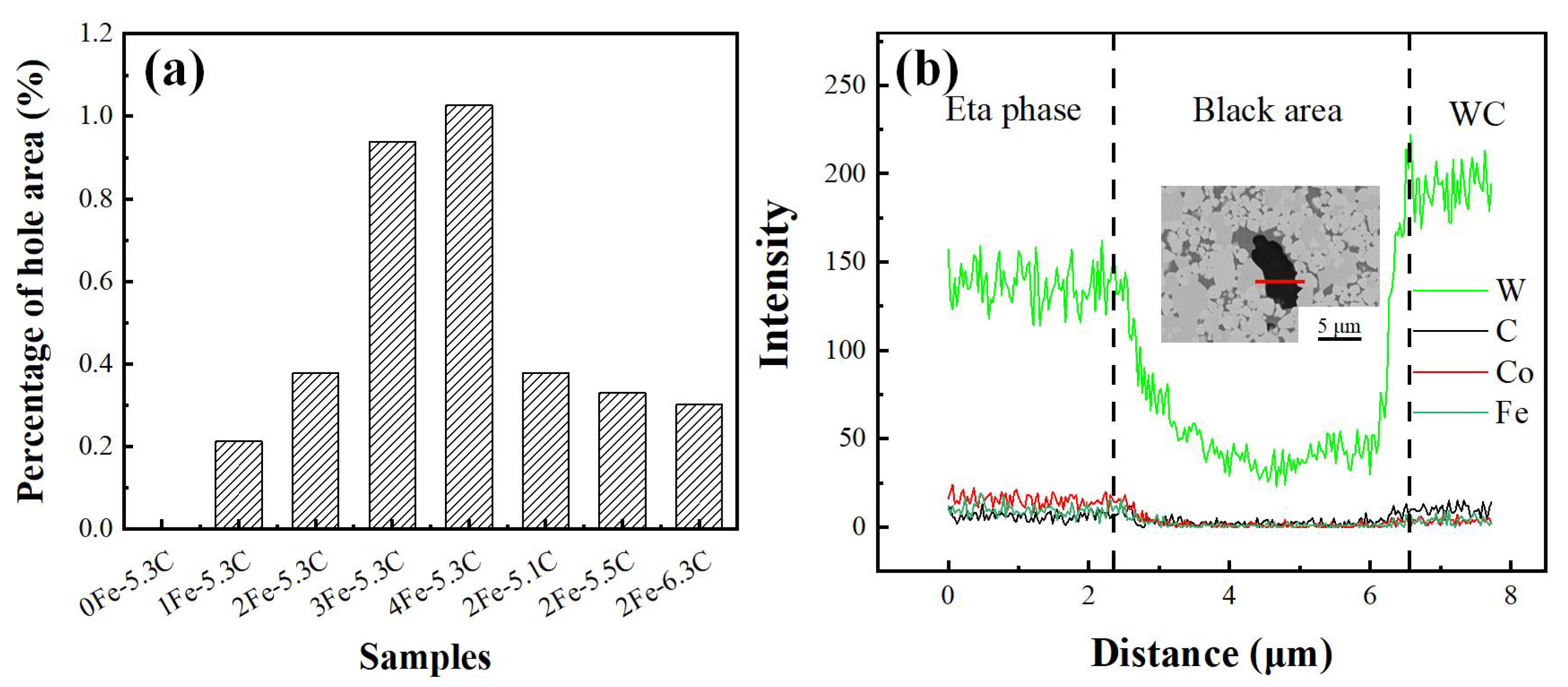
3.2. Analysis of the Density

Figure 10 illustrates that the density of the WC-13 (Co-Fe) composite decreases gradually with the increase of Fe content. The densification of WC-Co composites mainly depends on the volume shrinkage and the closure of micro-pores during liquid sintering. The high content of liquid metal and the good wettability between WC and the liquid metal are important factors for densification sintering. Both the XRD pattern in Figure 2 and the volume fraction of the eta phase in Figure 5 demonstrate that the proportion of the eta phase increases with the increase of Fe content. This means that, during the sintering process, the liquid Co decreases, which leads to the inhibition of shrinkage behavior and the decrease of density.
Figure 11 and Figure 12a further demonstrate the distribution and area fraction of micro-pore with different additions of Fe and C. With the increase of Fe content from 1% to 4%, the area fraction of micro-pore increased from 0.21% to 1.03%, while with the increase of C content the area fraction of micro-pore significantly decreased, and the fraction in the 2Fe-6.3C sample decreased to 0.30%. This is consistent with the change trend of density in Figure 10. According to the EDS analysis in Figure 12b, the content of all elements of W, Fe and Co is extremely low in the micro-pore, which is useful to prove the existence of the micro-pore in the composites containing Fe.
With the addition of C, the fraction of eta phase decreases and the content of liquid Co increases. Interestingly, comparing the density of 2Fe-6.3C and 0Fe-5.3C samples, the density of the 2Fe-6.3C sample was lower than that of 0Fe-5.3C samples, although the eta phase in the 2Fe-6.3C sample was completely eliminated. The reasons for the decrease in density include: (i) the density of Fe is lower than that of Co; (ii) the increase of porosity. It can be seen from Figure 11 that there are some micro-pores in the 2Fe-6.3C sample, which can be explained by the lower wettability of WC in CoFe than in Co [30,31].

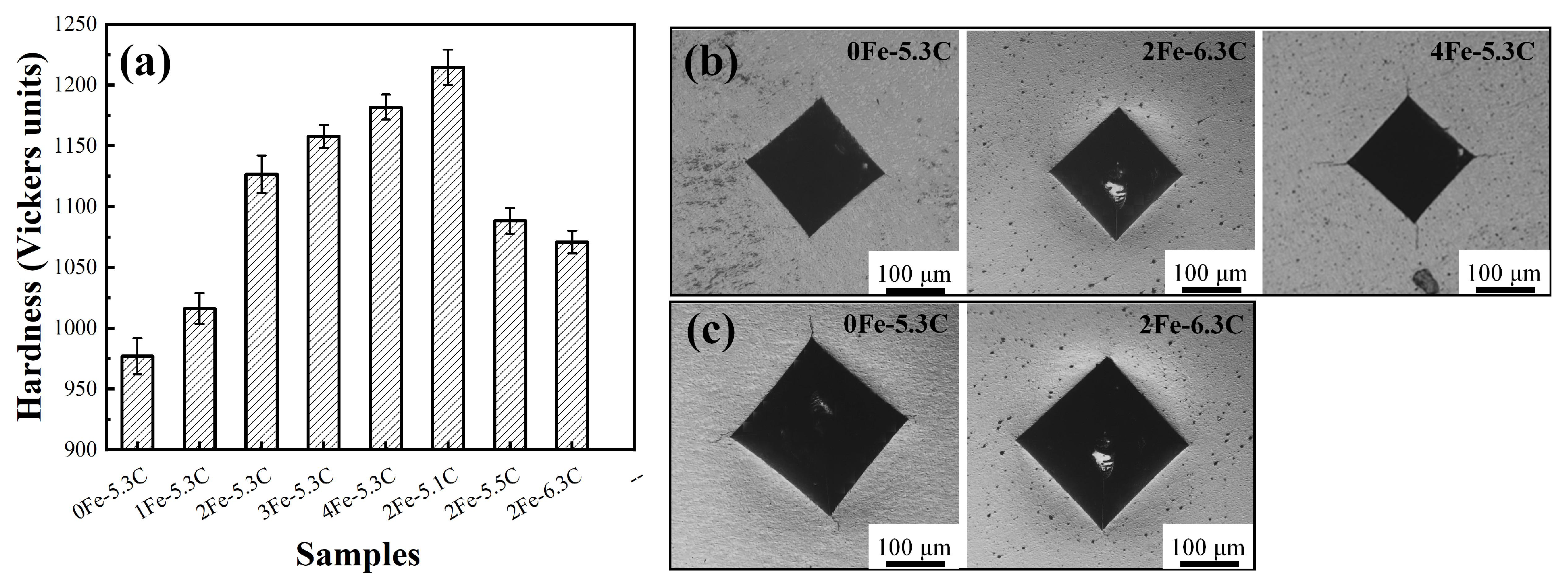
3.3. Mechanical Properties

When powder metallurgy is used to fabricate WC-Co composites, the key to the sintering process is to remove porosity and make the composite compact, and to bond different WC grains together with metal. Especially in the process of liquid phase sintering, WC particles rearrange, dissolve and precipitate in the liquid phase binder, thus further removing the composite porosity. The hardness H affected by porosity can be described by the following formula [32]:
H = H 0 exp b ρ
where ρ is the porosity, and H0 and b are constants. With the increase of porosity, the hardness decreases rapidly. The quantitative effect of grain size on hardness can be expressed by the Hall-Petch relationship [33]:
H = H 0 + k d 1 2
where H0 and k are constants, and d is the grain size of WC. The hardness decreases with the increase of grain size. However, when the addition of Fe increased from 0 to 4%, the porosity ρ and the grain size d increased (Figure 3 and Figure 6), but hardness also increased (Figure 13). This is because the hardness of WC-Co-based composites is also affected by the eta phase. It is well known that the higher the content of the eta phase, the lower the proportion of the binder phase. The eta phase is an intermetallic compound, and its hardness is significantly higher than that of the metal binder phase. Therefore, the eta phase is the dominant factor affecting the hardness in samples of 0Fe-5.3C, 1Fe-5.3C, 2Fe-5.3C, 3Fe-5.3C, 4Fe-5.3C, 2Fe-5.1C. When the Fe content increases from 0 to 4%, the eta phase grows abnormally and the area fraction of the eta phase significantly increases to 45.3%, leading to an obvious increase in hardness from 979 HV30 to 1185 HV30, and the increase in average crack length from 0 μm to 47 μm.
On the other hand, the addition of C increases the grain size, and especially, significantly, decreases the eta phase, leading to the clear decrease of hardness, although the decrease of porosity (Figure 3) is beneficial to the increase of hardness. Therefore, the 2Fe-6.3C sample without eta phase has lower hardness than other samples containing 2% Fe. Surprisingly, compared with the hardness 979 HV30 of the 0Fe-5.3C sample without Fe addition, the hardness of the 2Fe-6.3C sample clearly increases to 1071 HV30 by adding Fe and C and, moreover, it also has good fracture toughness and the average crack length decreases to 0 μm, as shown in Figure 13b. The disappearance of the eta phase can strengthen the skeleton structure of WC, which is very beneficial to synergistically increasing the hardness and toughness [34].
As the cracks cannot be observed in the 0Fe-5.3C and 2Fe-6.3C samples in the hardness test under 30 kg pressure (Figure 13b), the pressure of hardness was increased to 50 kg and two samples had obviously different crack morphology. Clear cracks appeared at the corners of the Vickers hardness indentation in the 0Fe-5.3C sample, while the 2Fe-6.3C sample still had no cracks. However, unlike hardness, fracture toughness is more difficult to assess accurately, especially in brittle materials. The Godse and Gurland’s model (GGM) given in the literature [35] can evaluate the fracture toughness in WC-Co composites with 10%–25% Co. The model formula is as follows.
K I c = R λ + d E σ B 1 C V W C C 1
where C, d and VWC are the contiguity, grain size and volume fraction of the carbide phase, respectively; λ is the binder mean free path; R is a floating parameter calculated on the basis of best fitting with experimental results, C1 is taken from McMeeking’s work as 0.54, E′ is the ratio of elastic modulus to Poisson’s ratio, σB is the binder effective flow stress. E′ can be calculated by using Equation (4) for plane stress:
E = E 1 V 2
where E and V are elastic modulus and Poisson’s ratio. According to reports [36], 600 Gpa and 619 Gpa were used for E and 0.23 and 0.22 for V in 0Fe-5.3C and 2Fe-6.3C samples, respectively. Additionally, σB is the effective flow stress of binder, calculated by using Equation (5) as proposed by Sigl and Fischmeister:
σ B = 480 + 1550 λ MPa
The adjacency degree and the mean free path of the Co phase can be measured from the SEM image. In the 0Fe-5.3C sample they are 0.27 and 0.39 μm, while in the 2Fe-6.3C sample they are 0.31 and 0.42 μm. It is noted that the grain size of the 2Fe-6.3C sample is larger than that of 0Fe-5.3C, which is in agreement with the report [37] that the average free path of the Co phase increases with the increase of WC grain size. Then, the KIC can be calculated by the Formula (3). The KIC of the 0Fe-5.3C sample and the 2Fe-6.3C sample is 29.6 MPa∙m1/2 and 31 MPa∙m1/2, respectively. Eta phase exists in the 0Fe-5.3C sample, which is unfavorable to the fracture toughness [38]. The calculation results show that the fracture toughness of the 2Fe-6.3C sample is slightly higher than that of the 0Fe-5.3C sample, which are consistent with the experimental results in Figure 13c.
The toughness of WC-based composites is mainly contributed by the metal binder phase. The eta phase was completely eliminated in the 2Fe-6.3C sample, as seen in Figure 2 and Figure 5, leading to the highest proportion of binder phase compared with other samples in Figure 13a. Furthermore, the density of Fe (7.86 g/cm3) is significantly lower than that of Co (8.9 g/cm3). Therefore, after replacing Co with Fe of the same weight, the volume fraction of the binder increases, resulting in a higher average free path of the 2Fe-6.3C sample. In addition, CoFe binder has higher hardness than Co binder. This is because Fe replaces the occupation of Co in the binder based on the crystal structure diagram as illustrated in Figure 8, which inevitably leads to lattice distortion and solution strengthening. Moreover, the formation of the B2 ordered structure further produces the ordered strengthening. Thus, the strengthening of the binder phase induced by the addition of Fe is the main reason that the hardness of the 2Fe-6.3C sample is significantly higher than that of the 0Fe-5.3C sample.
It should be pointed out that the hardness of WC based composites is significantly lower than that reported in low pressure sintering and SPS sintering [36] due to the simple pressureless sintering method adopted in this paper. However, the samples have excellent fracture toughness, especially the 2Fe-6.3C sample, which did not crack in the hardness test. This is significantly higher than the reported WC-13Co composite [39].
Consequently, adding 2% Fe to the WC-13Co composites increases the porosity, but by adjusting the carbon content, the hardness can be significantly improved without obviously damaging the toughness, although the porosity will damage the bending property [13]. When WC-based composites perform with low requirements for bending strength, the beneficial exploration of the current study can provide a useful reference on the control of the eta phase, binder phase and porosity for saving cobalt resources and reducing raw material costs in industrial production.

4. Conclusions

WC-13 (Co-Fe) composites were prepared by pressureless sintering at 1430 °C. The effects of Fe and C additions on the microstructure and mechanical properties of composites were investigated. The conclusions were drawn as follows.
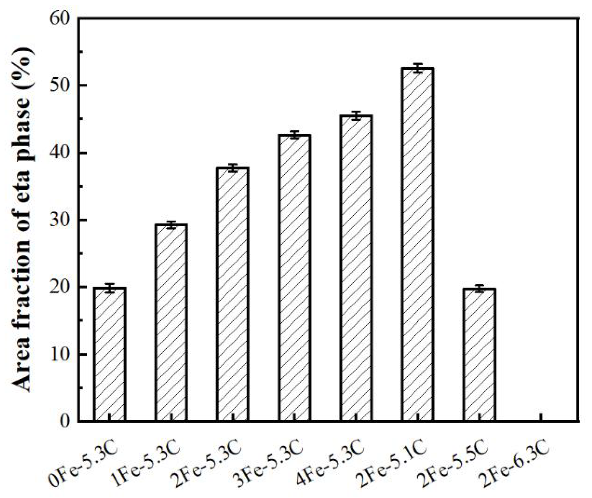
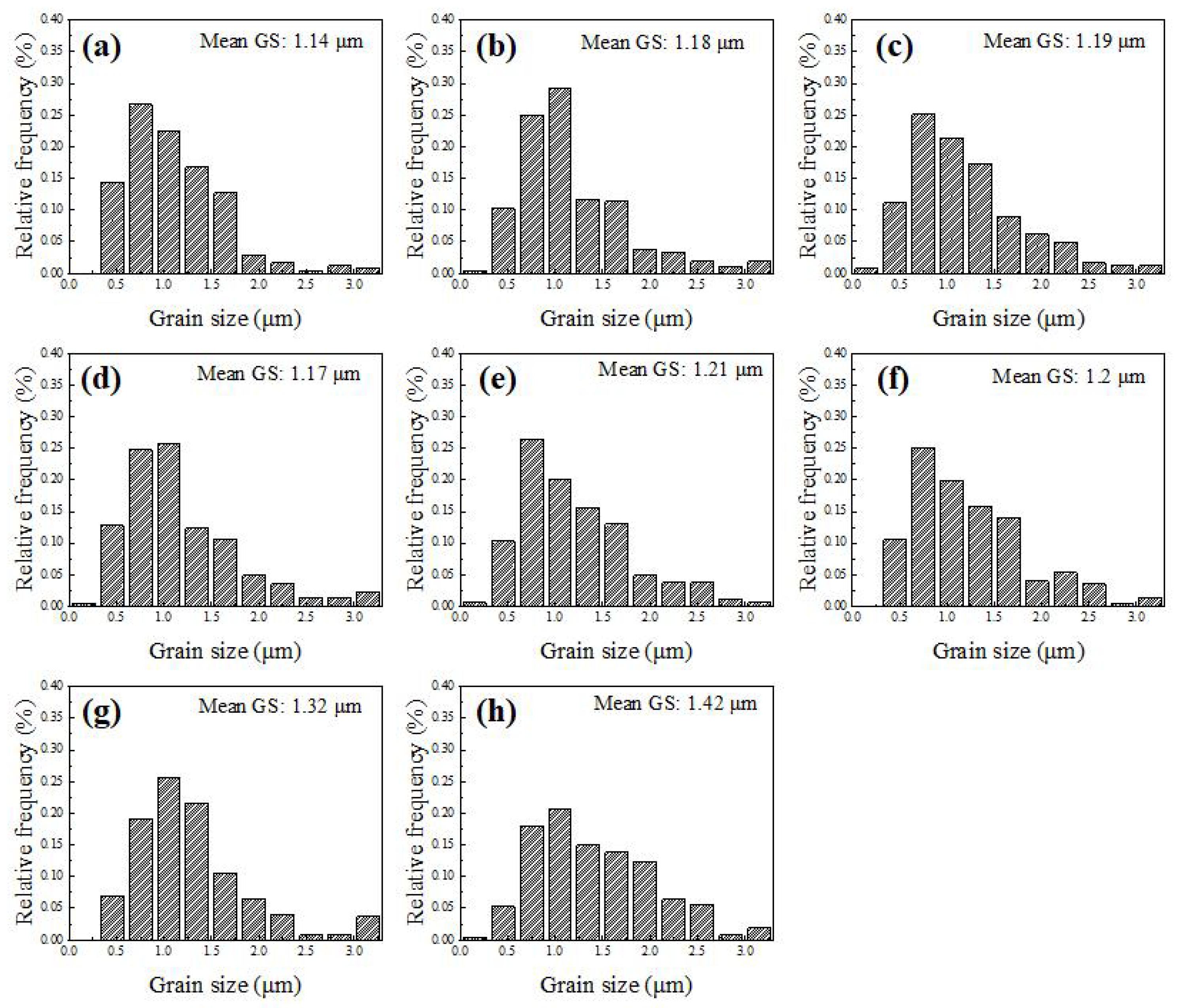
The addition of Fe significantly promoted the formation of eta phase in WC-13 (Co-Fe) composites, and slightly promoted the growth of WC. With the increase of Fe content from 0 to 4%, the content of the eta phase increases significantly from 20% to 45.3%, and the grain size of WC increases from 1.14 μm to 1.21 μm. The addition of C inhibited the eta phase and further promoted the growth of WC. With the increase of C content from 0 to 1%, the content of the eta phase decreases from 37.6% to 0, and the grain size of WC increases from 1.19 μm to 1.42 μm.
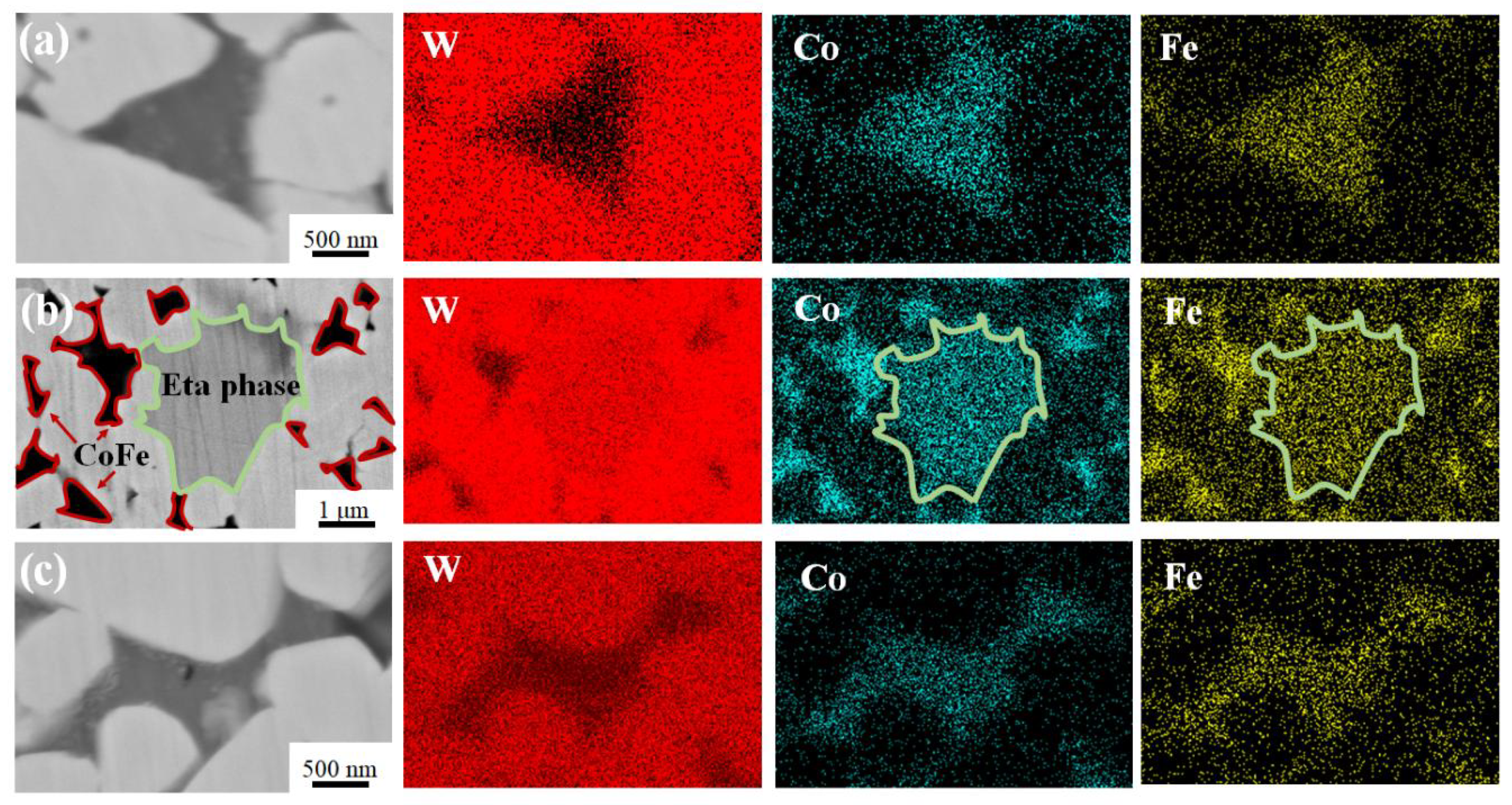
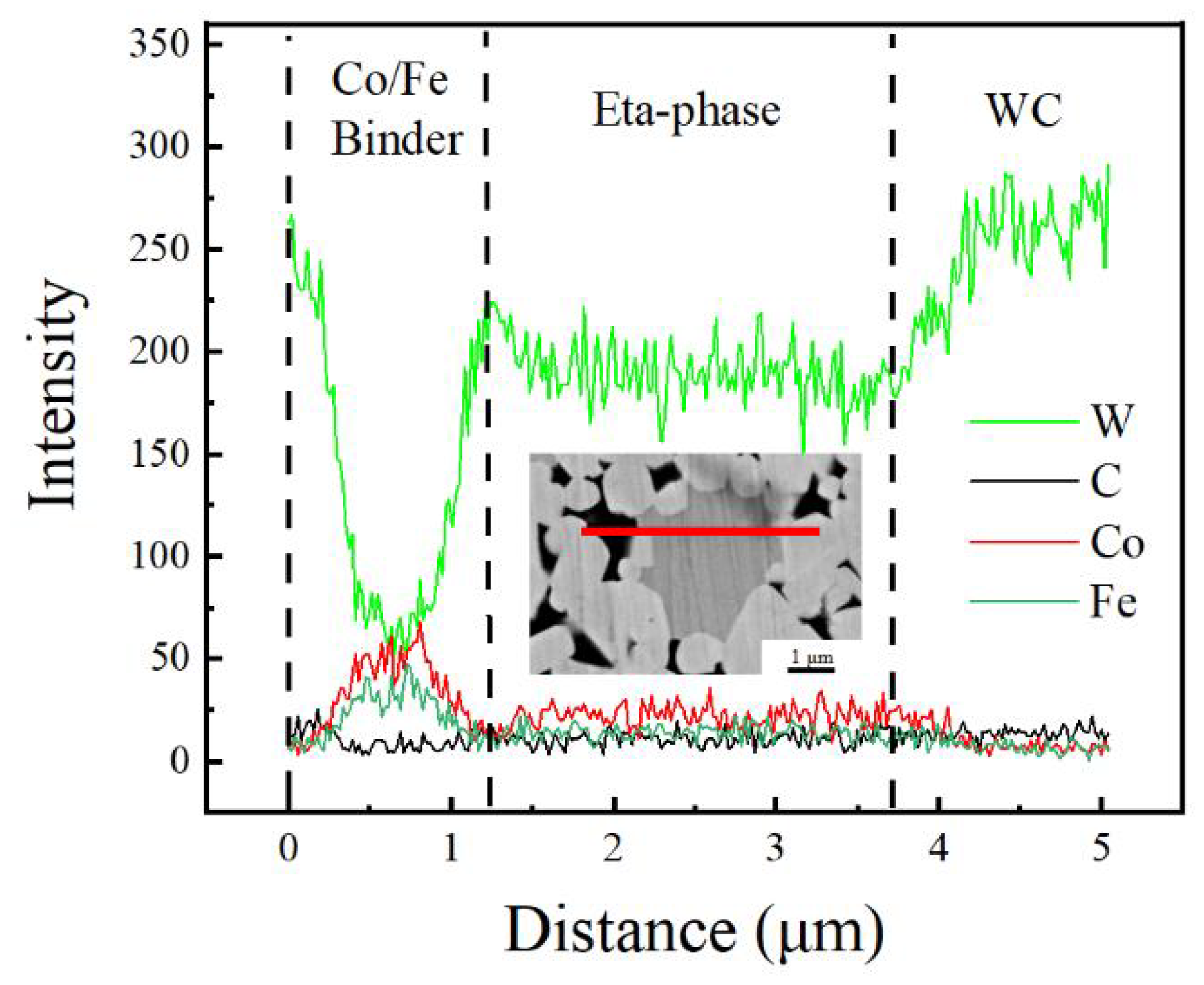
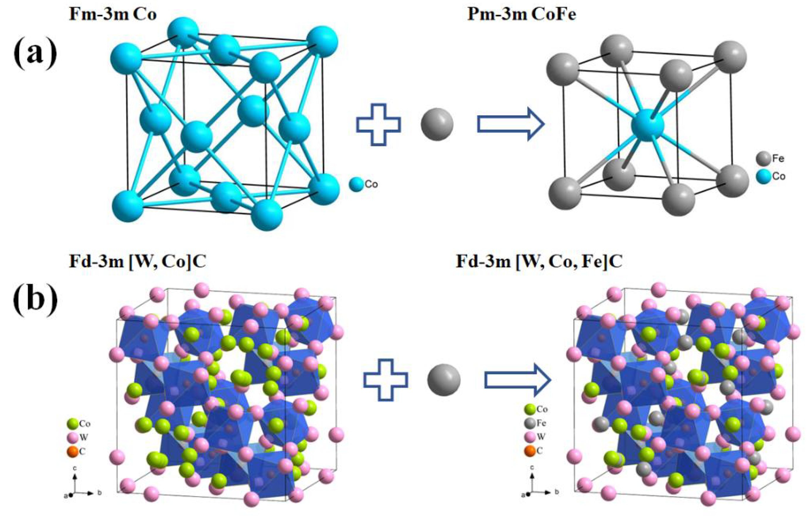
The added Fe mainly exists in the eta phase and the binder phase. Compared with the WC-13Co composite, the added Fe occupies the Co position instead of the W position in the lattice of the eta phase. When the eta phase is eliminated by adjusting the content of C, Fe uniformly exists in the binder, and after adding a relatively small amount of 2% Fe, the binder phase of fcc-Co transforms into sc-CoFe.
WC-13 (Co-Fe) composites with 2% Fe and 1% C added obtain good matching of hardness and toughness. The fracture toughness is slightly higher than that of WC-13% Co without the addition of Fe and C, and the hardness also increases by 9.4%. The hardness of composites is mainly controlled by the content of WC and eta phases, and is not very sensitive to porosity.

Author Contributions

Conceptualization, J.L. and V.J.; methodology, J.L. and X.L.; formal analysis, X.L.; investigation, X.L. and J.Z.; resources, X.Z., J.Z. and Q.Z.; writing—original draft preparation, X.L.; writing—review and editing, J.L.; All authors have read and agreed to the published version of the manuscript.

Funding

This work was funded by the Fundamental Research Funds for the Central Universities (No. N2002008), and Science and Technology Plan Project of Shenfu Demonstration District (2021JH05).

Institutional Review Board Statement

Not applicable.

Informed Consent Statement

Not applicable.

Data Availability Statement

Not applicable.

Conflicts of Interest

The authors declare no conflict of interest.

References

  1. Yu, K.; Ma, H.T.; Guo, Y.H.; Sun, Z.; Dong, Y.; Alexandrov, I.V.; Prokofiev, E.A.; Chang, H. Microstructure evolution and mechanical properties of copper coated graphene nanoflakes/pure titanium matrix composites. Mater. Charact. 2022, 194, 112433. [Google Scholar] [CrossRef]
  2. Ozer, M.; Aydogan, S.I.; Cinici, H.; Ozer, A. Effects of sintering techniques and parameters on microstructure and mechanical properties of Al-15Si-2,5Cu-0.5Mg compacts and Al-15Si-2,5Cu-0.5Mg/B4C composites. Mater. Today Commun. 2022, 30, 103192. [Google Scholar] [CrossRef]
  3. Ghabezi, P.; Harrison, N.M. Indentation characterization of glass/epoxy and carbon/epoxy composite samples aged in artificial salt water at elevated temperature. Polym. Test. 2022, 110, 107588. [Google Scholar] [CrossRef]
  4. Wang, R.; Deng, J.X.; Zhang, Z.H.; Lu, Y.; Li, X.; Wu, J. Microstructure and tribological properties of Ni3Al-Cr3C2/Ni3Al micro-laminate composite films fabricated by electrohydrodynamic atomization technique. Vacuum 2022, 200, 110979. [Google Scholar] [CrossRef]
  5. Lu, Z.Y.; Du, J.; Sun, Y.; Su, G.; Zhang, C.; Kong, X. Effect of ultrafine WC contents on the microstructures, mechanical properties and wear resistances of regenerated coarse grained WC-10Co cemented carbides. Int. J. Refract. Met. Hard Mater. 2021, 97, 105516. [Google Scholar] [CrossRef]
  6. Rayón, E.; Bonache, V.; Salvador, M.D.; Roa, J.; Sánchez, E. Hardness and Young’s modulus distributions in atmospheric plasma sprayed WC-Co coatings using nanoindentation. Surf. Coat. Technol. 2011, 205, 4192–4197. [Google Scholar] [CrossRef]
  7. Garcia, J. Influence of Fe-Ni-Co binder composition on nitridation of cemented carbides. Int. J. Refract. Met. Hard Mater. 2012, 30, 114–120. [Google Scholar] [CrossRef]
  8. Li, H.Y.; Dong, C.F.; Xiao, K.; Li, X.; Zhong, P. Relationship Between Microstructure and Corrosion Behavior of Cr12Ni3Co12Mo4W Ultra-High-Strength Martensitic Stainless Steel. Acta Metall. Sin. 2016, 29, 1064–1072. [Google Scholar] [CrossRef] [Green Version]
  9. Thomas, S.V.; Willard, M.A.; Martone, A.; Heben, M.J.; Solomon, C.V.; Welton, A.; Boolchand, P.; Ewing, R.C.; Wang, C.; Bud’Ko, S.L.; et al. Processing of soft magnetic fine powders directly from as-spun partial crystalline Fe77Ni5.5Co5.5Zr7B4Cu ribbon via ball mill without devitrification. IEEE Trans. Magn. 2020, 56, 1–9. [Google Scholar] [CrossRef]
  10. Pu, J.; Han, M.T.; Wang, T.; Zhu, X.; Lu, M.; Chen, J.; Liu, W.; Dai, Y.; Tan, Y. The enhanced confinement effect of double shell hollow mesoporous spheres assembled with nitrogen-doped copper cobaltate nanoparticles for enhancing lithium-sulfur batteries. Electrochim. Acta. 2022, 404, 139597. [Google Scholar] [CrossRef]
  11. Roulon, Z.; Missiaen, J.M.; Lay, S. Carbide grain growth in cemented carbides sintered with alternative binders. Int. J. Refract. Met. Hard Mater. 2020, 86, 105088. [Google Scholar] [CrossRef]
  12. Uhrenius, B.; Pastor, H.; Pauty, E. On the composition of Fe-Ni-Co-WC-based cemented carbides. Int. J. Refract. Met. Hard Mater. 1997, 15, 139–149. [Google Scholar] [CrossRef]
  13. Shon, I.J.; Jeong, I.K.; Ko, I.K.; Doh, J.M.; Woo, K.D. Sintering behavior and mechanical properties of WC-10Co, WC-10Ni and WC-10Fe hard materials produced by high-frequency induction heated sintering. Ceram. Int. 2009, 35, 339–344. [Google Scholar] [CrossRef]
  14. Biurrun, T.S.; Cabezas, L.L.; Cuadrado, J.N.; Lopez, F.I.; Martinez-Pampliega, R.; Sánchez-Moreno, J.M. Densification of WC-Fe-Ni-Co-Cr cemented carbides processed by HIP after sintering: Effect of WC powder particle size. Int. J. Refract. Met. Hard Mater. 2023, 110, 105994. [Google Scholar] [CrossRef]
  15. Tarraste, M.; Kübarsepp, J.; Juhani, K.; Mere, A.; Kolnes, M.; Viljus, M.; Maaten, B. Ferritic chromium steel as binder metal for WC cemented carbides. Int. J. Refract. Met. Hard Mater. 2018, 73, 183–191. [Google Scholar] [CrossRef]
  16. Wittmann, B.; Schubert, W.D.; Lux, B. WC grain growth and grain growth inhibition in nickel and iron binder hardmetals. Int. J. Refract. Met. Hard Mater. 2002, 20, 51–60. [Google Scholar] [CrossRef]
  17. Gao, Y.; Luo, B.H.; He, K.J.; Zhang, W.W.; Bai, Z.H. Effect of Fe/Ni ratio on the microstructure and properties of WC-Fe-Ni-Co cemented carbides. Ceram. Int. 2018, 44, 2030–2041. [Google Scholar] [CrossRef]
  18. Kakeshita, T.; Wayman, C.M. Martensitic transformations in cermets with a metastable austenitic binder I: WC-(Fe-Ni-C). Mater. Sci. Eng. A 1991, 141, 209–219. [Google Scholar] [CrossRef]
  19. Guo, Z.X.; Xiong, J.; Yang, M.; Wang, J.; Sun, L.; Wu, Y.; Chen, J.; Xiong, S. Microstructure and properties of Ti(C,N)-Mo2C-Fe cermets. Int. J. Refract. Met. Hard Mater. 2009, 27, 781–783. [Google Scholar] [CrossRef]
  20. Chang, S.H.; Chang, P.Y. Investigation into the sintered behavior and properties of nanostructured WC-Co-Ni-Fe hard Metal alloys. Mater. Sci. Eng. A 2014, 606, 150–156. [Google Scholar] [CrossRef]
  21. Schubert, W.D.; Fugger, M.; Wittmann, B.; Useldinger, R. Aspects of sintering of cemented carbides with Fe-based binders. Int. J. Refract. Met. Hard Mater. 2015, 49, 110–123. [Google Scholar] [CrossRef]
  22. Guillermet, A.F. Thermodynamic properties of the Co-W-C system. Metall. Trans. A 1989, 20, 935–956. [Google Scholar] [CrossRef]
  23. Markström, A.; Frisk, K.; Sundman, B. A revised thermodynamic description of the Co-W-C system. J. Phase Equilib. Diffus. 2005, 26, 152–160. [Google Scholar] [CrossRef]
  24. Fernandes, C.M.; Vilhena, L.M.; Pinho, C.M.S.; Oliveira, F.; Soares, E.; Sacramento, J.; Senos, A. Mechanical characterization of WC-10wt% AISI 304 cemented carbides. Mater. Sci. Eng. A 2014, 618, 629–636. [Google Scholar] [CrossRef]
  25. Zhou, P.; Peng, Y.B.; Buchegger, C.; Du, Y.; Lengauer, W. Experimental investigation and thermodynamic assessment of the C-Co-Fe-Ni-W system. Int. J. Refract. Met. Hard Mater. 2016, 54, 60–69. [Google Scholar] [CrossRef]
  26. Rabouhi, H.; Khelfaoui, Y.; Khireddine, A. Comparative study by image analysis of WC-Co alloys elaborated by liquid phase sintering and hot isostatic pressing. Ann. Chim.-Sci. Mater. 2020, 44, 263–269. [Google Scholar] [CrossRef]
  27. Wei, C.B.; Song, X.Y.; Fu, J.; Lv, X.; Wang, H.; Gao, Y.; Zhao, S.; Liu, X. Effect of Carbon Addition on Microstructure and Properties of WC-Co Cemented Carbides. J. Mater. Sci. Technol. 2012, 28, 837–843. [Google Scholar] [CrossRef]
  28. Chang, S.H.; Chang, M.H.; Huang, K.T. Study on the sintered characteristics and properties of nanostructured WC-15 wt% (Fe-Ni-Co) and WC-15 wt% Co hard metal alloys. J. Alloys Compd. 2015, 649, 89–95. [Google Scholar] [CrossRef]
  29. Konyashin, I.; Hlawatschek, S.; Ries, B.; Lachmann, F.; Dorn, F.; Sologubenko, A.; Weirich, T. On the mechanism of WC coarsening in WC-Co hardmetals with various carbon contents. Int. J. Refract. Met. Hard Mater. 2009, 27, 234–243. [Google Scholar] [CrossRef]
  30. Upadhyaya, G.S.; Bhaumik, S.K. Sintering of submicron WC-10wt.%Co hard metals containing nickel and iron. Mater. Sci. Eng. A 1988, 105–106, 249–256. [Google Scholar] [CrossRef]
  31. Pan, Y.F.; Liu, A.J.; Huang, L.; Du, Y.; Jin, Y.; Yang, X.; Zhang, J. Effects of metal binder content and carbide grain size on the microstructure and properties of SPS manufactured WC-Fe composites. J. Alloys Compd. 2019, 784, 519–526. [Google Scholar] [CrossRef]
  32. Gao, Y.; Luo, B.H.; He, K.J.; Jing, H.B.; Bai, Z.H.; Chen, W.; Zhang, W.W. Mechanical properties and microstructure of WC-Fe-Ni-Co cemented carbides prepared by vacuum sintering. Vacuum 2017, 143, 271–282. [Google Scholar] [CrossRef]
  33. Liu, G.H.; Li, R.D.; Yuan, T.C.; Zhang, M.; Zeng, F. Spark plasma sintering of pure TiCN: Densification mechanism, grain growth and mechanical properties. Int. J. Refract. Met. 2017, 66, 68–75. [Google Scholar] [CrossRef]
  34. Yang, G.J.; Gao, P.H.; Li, C.X.; Li, C.J. Simultaneous strengthening and toughening effects in WC-(nanoWC-Co). Scr. Mater. 2012, 66, 777–780. [Google Scholar] [CrossRef]
  35. Godse, R.; Gurland, J. Applicability of the critical strain fracture criterion to WC-Co hard metals. Mater. Sci. Eng. A 1988, 105–106, 331–336. [Google Scholar] [CrossRef]
  36. Sheikh, S.; M’Saoubi, R.; Flasar, P.; Schwind, M.; Persson, T.; Yang, J.; Llanes, L. Fracture toughness of cemented carbides: Testing method and microstructural effects. Int. J. Refract. Met. 2015, 49, 153–160. [Google Scholar] [CrossRef] [Green Version]
  37. Xu, Z.H.; Ågren, J. A modified hardness model for WC-Co cemented carbides. Mater. Sci. Eng. A 2004, 386, 262–268. [Google Scholar] [CrossRef]
  38. Li, X.; Zhang, X.W.; Zhang, J.F.; Zhang, Q.; Ji, V.; Liu, J.L. Effect of Mo and C additions on eta phase evolution of WC-13Co cemented carbides. Coatings 2022, 12, 1993. [Google Scholar] [CrossRef]
  39. Liu, K.; Wang, Z.H.; Yinet, Z.B.; Cao, L.; Yuan, J. Effect of Co content on microstructure and mechanical properties of ultrafine grained WC-Co cemented carbide sintered by spark plasma sintering. Ceram. Int. 2018, 44, 18711–18718. [Google Scholar] [CrossRef]
Figure 1. BSE-SEM of raw powders. (a) WC, (b) Co, (c) Fe, (d) W.
Coatings 13 00116 g001
Figure 2. XRD patterns of WC-13 (Co-Fe) composites with different contents of Fe and C (a) and the enlarged XRD patterns between 43° and 46° (b).
Coatings 13 00116 g002
Figure 3. Isopleth calculated with ThermoCalc software using TCFE10 database corresponding to the WC-13Co (Black) and WC-9Co-4Fe (Red) composites.
Coatings 13 00116 g003
Figure 4. BSE-SEM microstructure of composites, (a) 0Fe-5.3C, (b) 1Fe-5.3C, (c) 2Fe-5.3C, (d) 3Fe-5.3C, (e) 4Fe-5.3C, (f) 2Fe-5.1C, (g) 2Fe-5.5C, (h) 2Fe-6.3C.
Coatings 13 00116 g004
Figure 5. Area fraction of the eta phase of different WC-13 (Co-Fe) composites.
Coatings 13 00116 g005
Figure 6. EDS mapping of element distribution of different samples, (a) the binder phase of 2Fe-5.3C sample, (b) the binder and eta phases of 2Fe-5.3C sample, (c) the binder phase of 2Fe-6.3C sample.
Coatings 13 00116 g006
Figure 7. Elements’ distribution of binder phase, eta phase and WC phase in the 2Fe-5.3C sample.
Coatings 13 00116 g007
Figure 8. Crystal structure diagram of (a) binder phase of Co and CoFe and (b) eta phase of [W, Co]C and [W, Co, Fe]C.
Coatings 13 00116 g008
Figure 9. The grain size distribution in WC-13Co with different additions of Fe and C: (a) 0Fe-5.3C, (b) 1Fe-5.3C, (c) 2Fe-5.3C, (d) 3Fe-5.3C, (e) 4Fe-5.3C, (f) 2Fe-5.1C, (g) 2Fe-5.5C, (h) 2Fe-6.3C.
Coatings 13 00116 g009
Figure 10. The effects of addition of Fe and C on the densities of WC-13 (Co-Fe) composites.
Coatings 13 00116 g010
Figure 11. BSE-SEM microstructure of different composites, (a) 0Fe-5.3C, (b) 1Fe-5.3C, (c) 2Fe-5.3C, (d) 3Fe-5.3C, (e) 4Fe-5.3C, (f) 2Fe-5.1C, (g) 2Fe-5.5C, (h) 2Fe-6.3C.
Coatings 13 00116 g011
Figure 12. (a) Area fraction of the micro-pore in different WC-13 (Co-Fe) composites and (b) the EDS analysis around the micro-pore in the 2Fe-5.1C sample.
Coatings 13 00116 g012
Figure 13. The hardness (a) and the micrographs of Vickers’ indentations and induced surface cracking in different WC-Co-Fe samples under 30 kg (b) and 50 kg (c) pressure, respectively.
Coatings 13 00116 g013
Table 1. The nominal chemical compositions of WC-13(Co-Fe) composites (wt.%).
SamplesWCCoFeWCCtotal
0Fe-5.3C8713000C5.3
1Fe-5.3C8712100C5.3
2Fe-5.3C8711200C5.3
3Fe-5.3C8710300C5.3
4Fe-5.3C879400C5.3
2Fe-5.1C83.71123.30C5.1
2Fe-5.5C8711200.25C5.5
2Fe-6.3C8711201C6.3
Disclaimer/Publisher’s Note: The statements, opinions and data contained in all publications are solely those of the individual author(s) and contributor(s) and not of MDPI and/or the editor(s). MDPI and/or the editor(s) disclaim responsibility for any injury to people or property resulting from any ideas, methods, instructions or products referred to in the content.

