Toilet Assistive System Designed for the Reduction of Accidental Falls in the Bathroom Using Admittance Controller


Laboratory of automatic and 3D Intelligent Interaction, University of Quebec at Chicoutimi, Chicoutimi, QC G7H 2B1, Canada
*
Author to whom correspondence should be addressed.
Machines 2017, 5(4), 23; https://doi.org/10.3390/machines5040023
Submission received: 7 August 2017
/
Revised: 2 October 2017
/
Accepted: 4 October 2017
/
Published: 13 October 2017
Abstract
:This paper suggests an assistive system for the toilet with the objective of measuring human activities and to provide intelligent mechanical assistance to help seating and standing. The project intends to develop a seating assistance as a technical aid in order to reduce accidents and falls in the bathroom. The preferred technique is human-robot physical interaction algorithms known in collaborative robotics (cobot) and adapting it to a personalized assistance technology installed on a smart toilet. First, the design of the mechanical assistance is presented. Then, an admittance controller is designed and implemented in order to help the user in a similar way as a cobot could be used. This technique could be used to assist the user and improve balance with adequate training and an adequate configuration of the admittance controller.
1. Introduction
In Quebec (Canada), half of the people with a functional disability are the owners of their home or of their housing [1]. While 11% rent accommodation suitable for elderly people and 1.4% live in housing designed for people with reduced mobility [2], the majority wish to remain in their home, even if they have difficulty in carrying out their tasks of daily life. In particular, the bathroom is the place most conducive to an increase in the risk of falling because there are obstacles such as the toilet, tub, shower, and sink. Recent technological achievements can be exploited in order to provide personalized assistance to the users in the bathroom using a specific mechanism and control.
For an elderly person, seating and standing up in the bathroom is sometimes difficult, and the floor can be covered with different obstacles or different moist surfaces. This causes a potential increase of the risk of falling. Elders have much to offer to our communities, and we want them to be able to live healthily and independently in the community for as long as possible. The proportion of the risk of falling for older persons is 50% for the bathroom and 50% for all other parts of their home [3]. Accident rates with injuries increases significantly with age, especially when using the toilet: 7% for 14–24 year olds, and 52% for 85 years and over [4]. According to statistics, more than one third of people over 65 fall at least once a year, causing 65% of injuries in this age group [5]. There is little information about where the falls are most frequent in the home. However, bathrooms are commonly considered a particularly hazardous place [6]. In Canada, 7.8% of the population over the age of 65 already uses technical assistance such as a cane or a medical walker device [7], and our device could be used by these persons.
Recent technological achievements for the bathroom, such automated lifting mechanisms, and mobile applications can be exploited to provide personalized assistance to users in the bathroom [8,9,10]. For example, a previous toilet assistive system [8] was designed to lift the user up and down without support for forward pushing while standing or being seated. However, our proposed mechanism is designed to help the user by tilting and pushing forward in the same way as an electric lift armchair. Moreover, in [10], a mobile application was designed to manually adjust the toilet level and tilting, like in patent [11]. We suggest an automated machine and an admittance controller in order to assist the user without manual interaction with a software application.
The assessment of the risk associated with a fall in the bathroom involving the toilet requires the analysis of several factors. These factors may be extrinsic, including environmental hindrance, accessibility, and availability of assistive devices [12], and intrinsic, including the ability of a person to respond adequately to an imbalance. Moreover, passive [13] and active [14] technical aids have been proposed in several works, including the FRR (Friendly Rest Room) international project [15,16]. Our research program explores different avenues in order to support a person with a loss of autonomy or with reduced mobility in the fulfilment of daily activities in a smart home [17]. The smart home is composed of several technological tools (personal assistance) in order to decrease the load to medical personnel and informal caregivers. This habitat also contains a multitude of sensors able to assess human activities and detect sequences of problematic activities that can lead to a fall [18]. The project fits properly in the program, which aims to improve the quality of life of people with a loss of autonomy while increasing the retention of these people in their living environment.
The proposed approach consists of instrumenting the toilet (as suggested in [3]) with the objective of measuring human activities and providing automatic seating/standing assistance for reducing or adapting the effort. The goal is to help the person not to completely replace the subject’s efforts, but to adapt it in order to train the subject. The preferred technique resides in the use of human-robot physical interaction algorithms known in collaborative robotics [19,20,21] to control the assistance. An admittance controller is implemented as the main contribution of this paper, which includes a state machine for assistance. This system is automatic and does not need any command from the user. Therefore, it could be used as a training system for rehabilitation by adapting the value of the admittance model.
Following a review of the state of the art (Section 2) in technologies for friendly rest rooms and intelligent toilets, we describe the primary contribution of this paper, a mechanical design for controlling an assistive seat (Section 3) using an admittance controller, such that users can reduce their effort and accordingly reduce the risk of fall after this effort (Section 4). We then describe the method used to adapt the assistive force from the mechanism and the design and implementation of the admittance controller (Section 5).
2. Related Works
A study [22] published in the Netherlands in July 2005 refers to a hand holder adjustable with the adjustment of the height of the basin. The latter must be adjustable to eliminate the effect of a toilet seat fixed at a constant position. The results of this study show that the media settled in a specific way for each person promoted an aid to sit down and to rise without the loss of balance. However, there were certain areas of discomfort. Another study [13] was conducted in Austria for patients with multiple sclerosis between Decembers 2004 to February 2005. It validated the prototype of toilets that adjust the tilt angle and the height of the basin. The objective was to determine the extent to which quality of life was improved by the introduction of the prototype of the intelligent toilet. The results obtained show that the latter can effectively contribute to greater autonomy and functional independence of persons with a loss of autonomy. In 2003 [23], a cooperation of three universities from three different countries did research on the Swedish toilet prototype Gustavsberg. The results obtained show that persons with reduced mobility appreciated the vertical displacement and the media to hand of the toilet. In addition, the risk of falling was very low, according to the data collected by this study. In 1974, a model was produced as patent by an American company called Australia Hunter, where a model consists of frame with vertical moveable toilet seat controlled by hydraulic cylinders in order to lower and raise the seat by the user [24]. In closing, it is possible to conclude that all the studies have a point in common: a smart toilet promotes an improvement of the conditions of the quality of life of persons with loss of autonomy. The development of new technologies in this field responds to the needs of individuals and improves the conditions of their daily lives. The contribution of this paper is concentrated on two main points: (1) the design and modeling of the system of lifting the seat of the toilet and (2) the design of the interactive and automatic system in order to activate the seat. The system added to the toilet contains different sensors such as proximity, force, acceleration, and encoding rotation sensors. These sensors are used to detect human activities around the toilet and then activate the feedback controller in order to help the person automatically. In brief, the toilet must be able to interact and to attend to a user.
3. Suggested Assistive System
Two concepts have been chosen in order to develop personalized toilet assistance. First, there is the electric lift armchair that helps people to stand up effortlessly and safely. This is a very interesting approach to the design of the mechanism since it has the same objective to either support a person to get up or sit down. Therefore, a lifting platform with scissors geometry is designed for this function. This platform is a deployment model that achieves the desired height and takes up little space. This union of the two models described in the previous paragraph is made with the aim of designing and optimizing the mechanism to allow a person to use it in an appropriate environment.
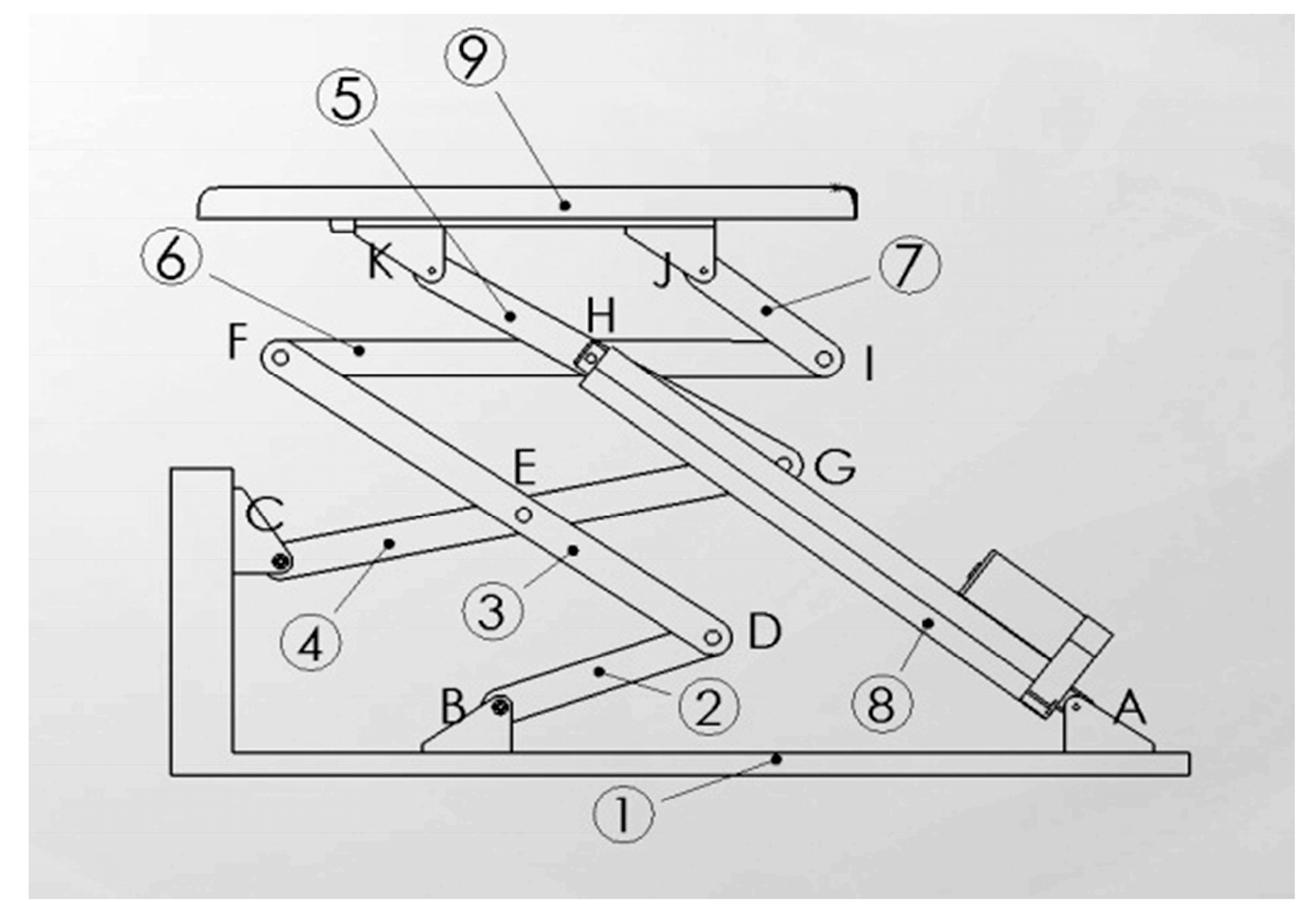
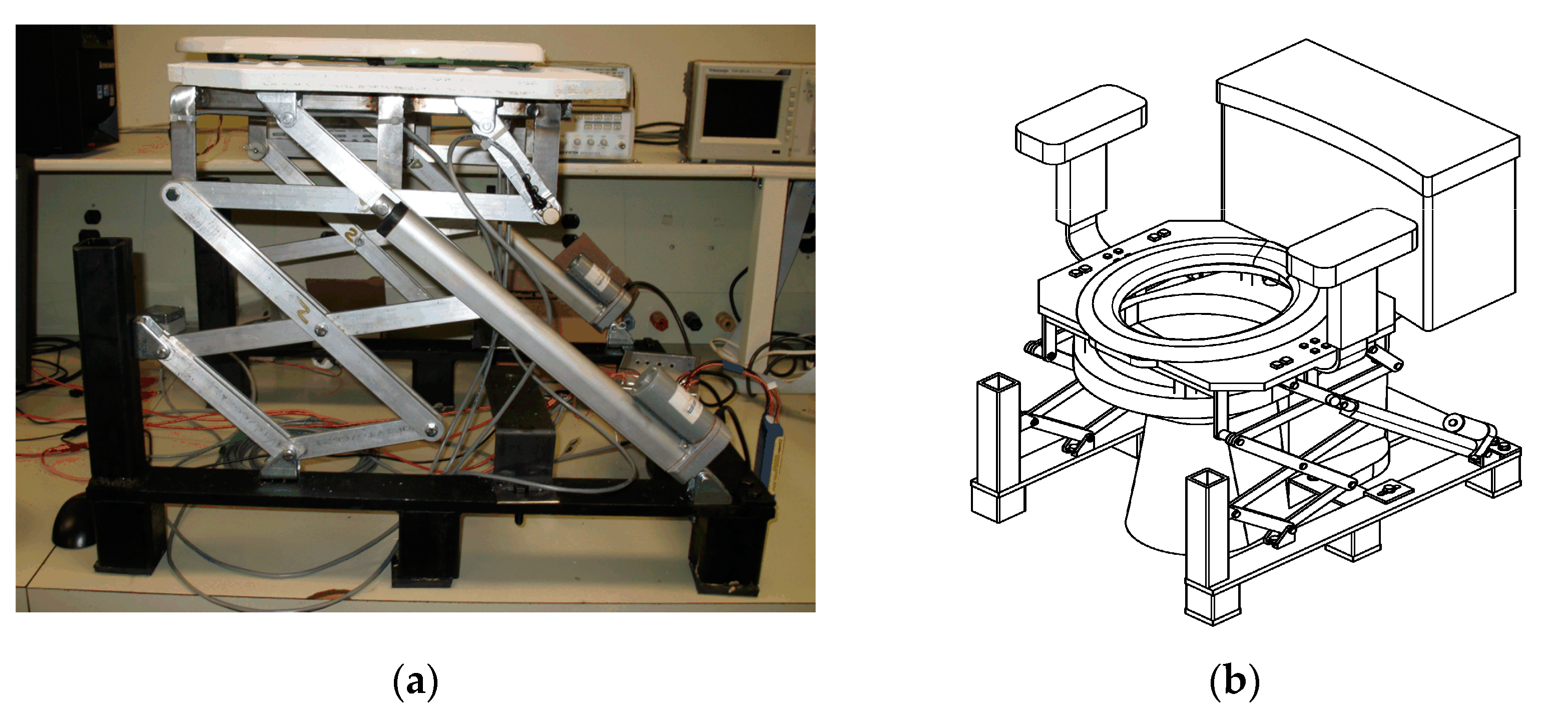
Modeling of the lifting mechanism (Figure 1) will be similar to a jack or the scissors of the lifting mechanism of a dump truck. It is composed of seven rigid bars linked by mechanical connections that allow movements of displacement and rotation in order to obtain the desired trajectory. With the help of two electric actuators, the seat of the toilet will allow a balanced position to a person with a loss of autonomy to aid the translational motion and rotation of the seat on the same axis. The rotation movement is ensured by a mechanism in the form of a chisel that is installed on the edge of the basin, which will help the two actuators to bear the weight of the person. The desired mechanism is described as closed kinematic chain parallel robotic mechanism. The mechanism has been designed from the initial position using Solidworks software (SOLIDWORKS 2016 x64 Edition.Ink) in order to observe the movement of the trajectory. Subsequently, it has been possible using the SAM software 6.1 (SAM software was developed by Artas, Nuenen, The Netherlands) to optimize the length of the seven rigid bars to obtain an appropriate trajectory. This designed was selected in order to reduce the number of actuators and therefore the final cost. The actuator could be pneumatic using an external high pressure tank, hydraulic using the pressure of water, or electric, such as an electric linear actuator. Two actuators were fixed, one on each side, located at point A, as shown in Figure 1. Also, the two actuators can be seen in the prototype in Figure 2a.
After consulting several clinicians and reviewing current design spectra, the following specifications were considered:
- consider a person weighing 100 kg;
- carry out load calculations for 100 kg;
- minimize prototype-manufacturing costs;
- establish logical programming of the sequence of events;
- train the person to sit and stand with an admittance controller.
The mechanism must adapt to the majority of North American toilets already installed in residences, hospitals, and long-stay centers. Unfortunately, toilets in hospitals are generally higher than those in residences. For this reason, the mechanism must be able to adapt to these different toilets.
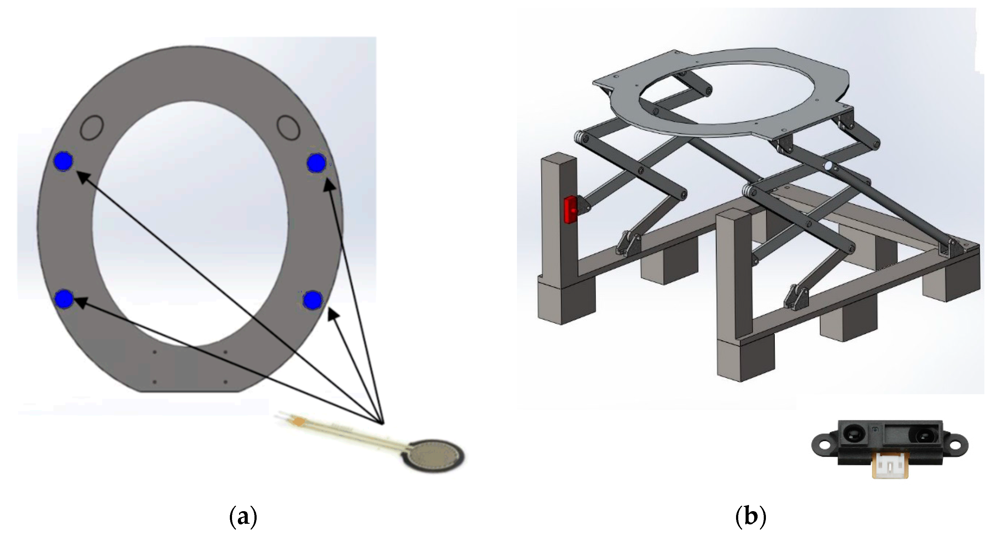
A full prototype has been manufactured and assembled (Figure 2), and four force sensors (FSR402 from Interlink, Westlake Village, CA, USA) have been placed, as indicated in Figure 3a. The number and the distribution of the sensors are important in order to obtain the distribution of the support (the payload) on the seat and then compute the center of pressure (COP). This COP gives information on the balance of the user and the user’s posture. For example, when the user’s mass is placed in front of the seat, this should be interpreted as a signal to begin stand up.
The IR proximity sensor shown in Figure 3b, (which is a Sharp GP2Y0A21YK0F IR Range Sensor −10 cm to 80 cm) is used for the proper functioning of the assistive algorithm. Its role is to detect the presence of a user to actuate the actuators and place the seat to accommodate the user. Using an infrared light ray, it is able to measure the exact distance of the user from the toilet. It is capable of performing a constant and reliable measurement and is not sensitive to the temperature variation of the objects or their reflectivity. These sensors use an optical principle to measure the distance: an infrared light beam is emitted, which reflects on the user present in the detection field (“range”) and strikes back onto a band of receivers [25].
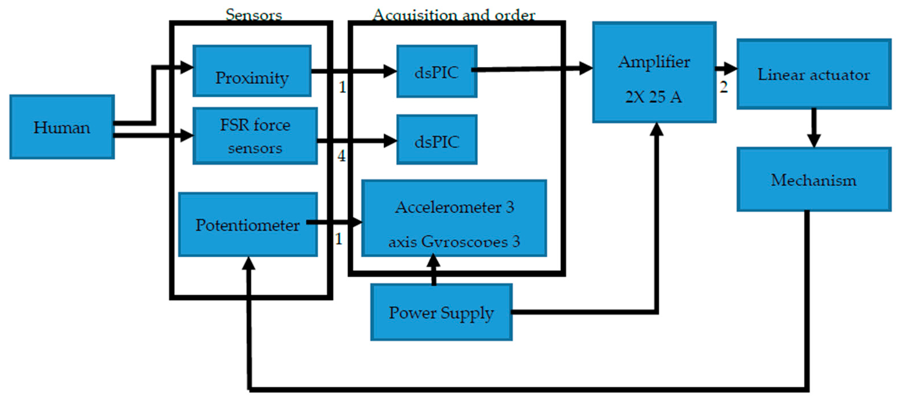
Several electronic components were used during this project. We used a Sabretooth motor amplifier 2 × 25 A (from DimensionEngineering), 12′′ Stroke 150 lb Force Linear Actuator, Matlab/Simulink with national instrument acquisition system, a 6-Cells lithium battery (22 V), and the various sensors already presented. In order to present a fully automated prototype, we added a DSP microcontroller: a dsPIC (16 bits Microchip microcontroller with Digital Signal Processing capability). The Simulink/MatLAB schematic could be compiled with Simulink Embedded Coder and then transferred to the dsPIC for a real-time and independent operation of the prototype. Our design is based on the same idea as a house alarm system, where the battery is located near the circuit breaker. Figure 4 shows all the electronic equipment of the project.
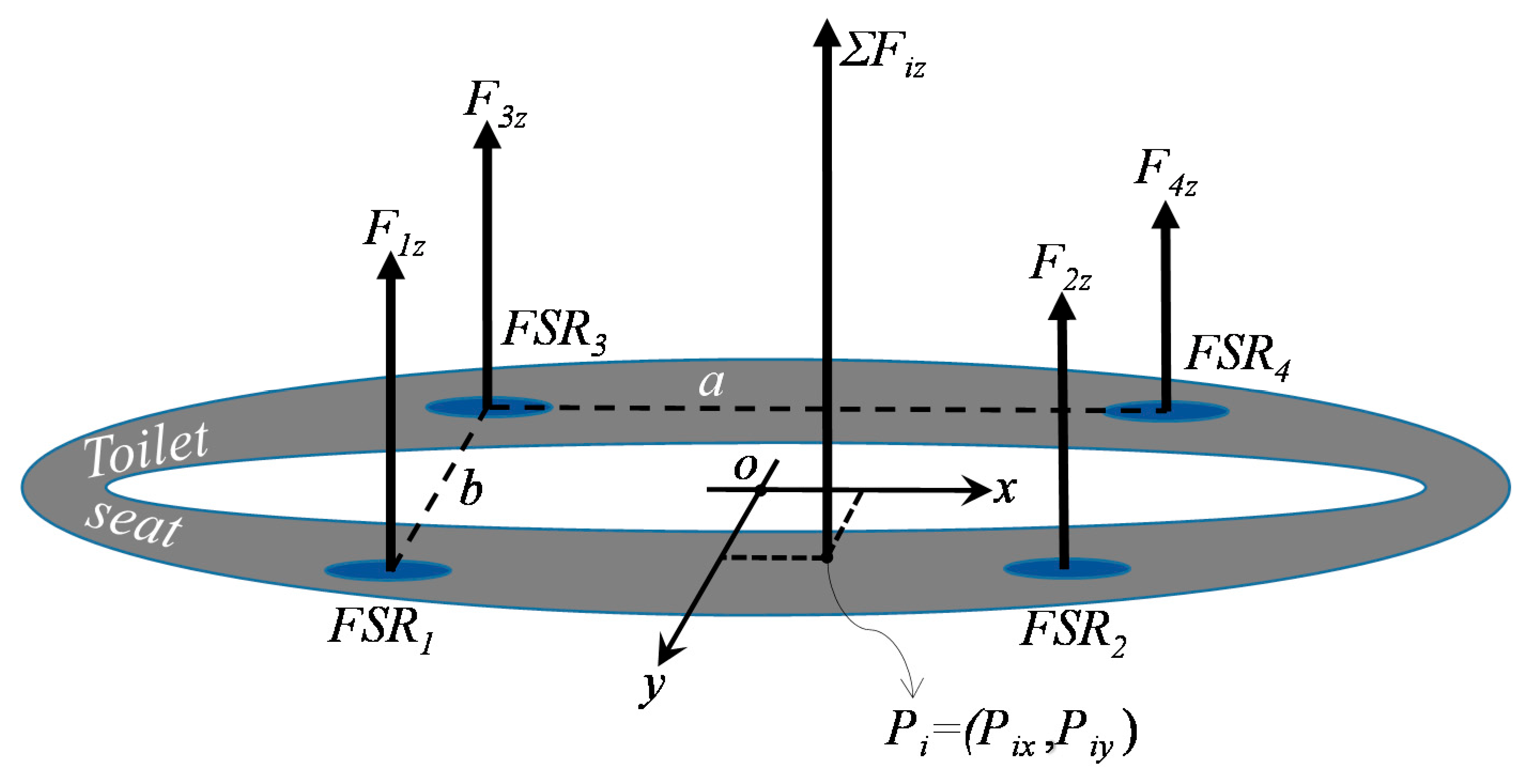
The center of pressure (COP) coming from the four FSR force sensors could be used as information on how the person sits and stands up. This information could help a clinician to find a risk of fall. The COP is known as the contact force distribution of the four force sensors on the sole surface, which can be replaced by a single equivalent force FiZ located at a position Pi (COP position, see the Figure 5). The displacements of the COP (which is the barycenter) on the surface of the sole were marked along the axes (OX) and (OY). The position Pi was then calculated as a barycenter using the following Equations (1) and (2):
where F1z, F2z, F3z, F4z are the scalar forces of the FSR respectively at a location Pi (i = 1 to 4) along the axis OZ (axis perpendicular to the surface of the sole). a and b represent the distances between two force sensors along the X and Y axes, respectively, and Fiz is the total scalar force of the four sensors. All scalar forces are functions of time t, while a and b are constant values.
Pix = (a/Fiz) × [(F2z + F1z) − (F4z + F3z)],
Piy = (b/Fiz) × [(F4z + F2z) − (F1z + F3z)],
4. Trajectory Planning and Optimization of the Mechanism
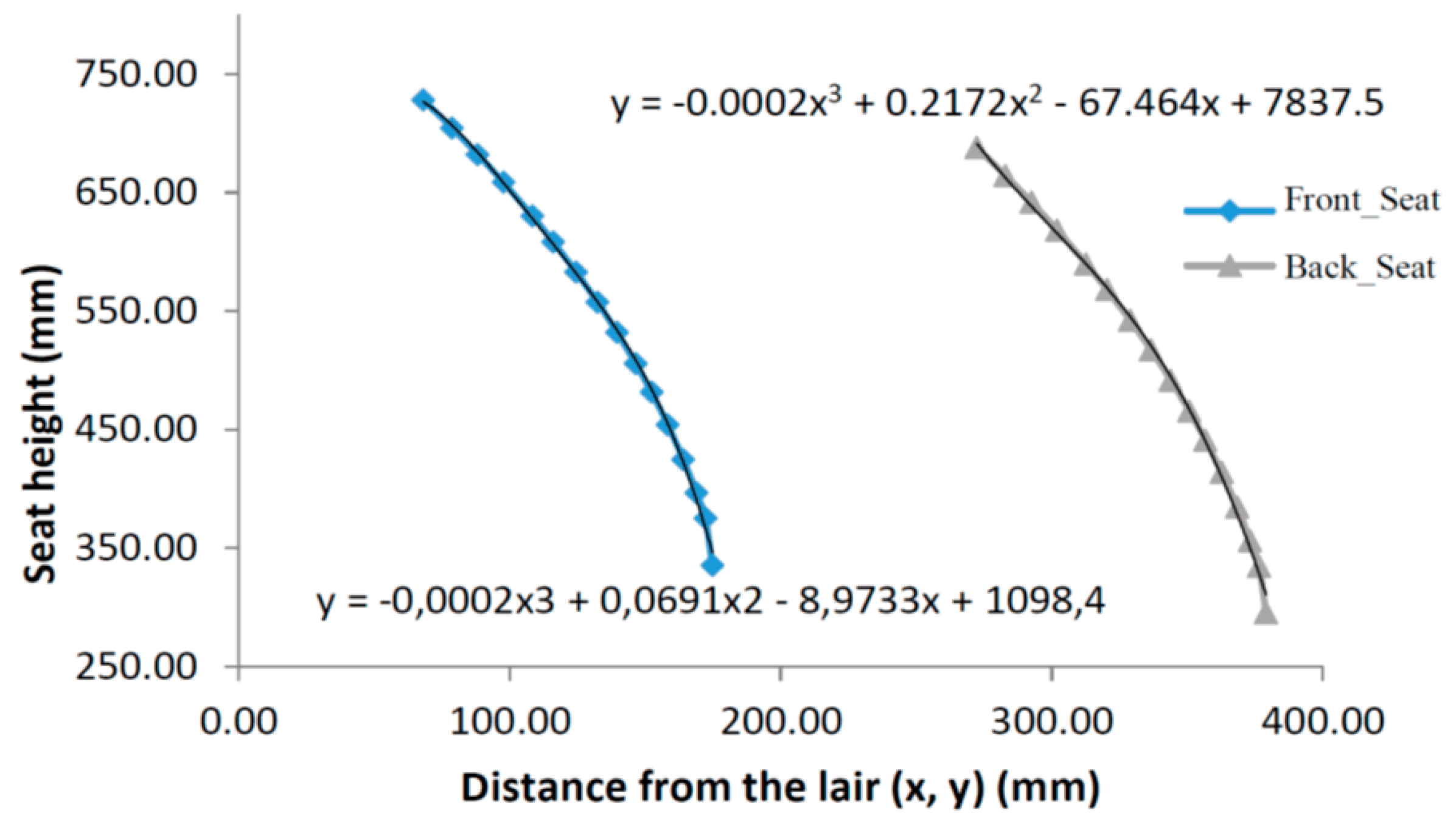
The proper position and trajectory of the seat are very important to provide a certain level of comfort to the user. This allows the user to avoid a steep at the time of sit and therefore will protect any imbalance or a risk of falling. According to statistics, the average height between the footplate and the bottom of the buttocks is 700 mm [26]. The main objective is to devise a mechanism so that the seat will reach the required position using a mean trajectory of the buttocks. The end of the trajectory (final pose) of the seat should be positioned forward toward the outside of the toilet to encourage support of the buttocks on the force sensors that will be installed under the seat. With Solidworks software (Figure 6), it was possible to size the coordinated mechanism path during the ascent and descent between the initial and final positions. Figure 7 shows the lines of path of the support mechanism.
The linear actuator (seen in Figure 1 and Figure 2) drives link number 5 at point G, forcing it to rotate counter clockwise (CCW) from it is initial position (Figure 8a) to its final position (Figure 8b). According to the motion of link 5 and the different link lengths, we can imagine that links number 2 and 7 will also rotate CCW, causing link number 10 (Figure 8a) to be raised while being tilted to reach its final position (Figure 8b), where the user will be supported to be raised and pushed when standing up. Also, while the user is being seated, the mechanism is tilted while being lowered, so the user is supported by the mechanism.
By taking the design of the starting trajectory, it was possible to improve the precision of the stroke of the coupling point with respect to the target trajectory by modifying the geometry of the mechanism within a predefined range. With the SAM software, the coordinates of all the points of reference realized in Excel are retracted, which minimizes the difference with the existing points by modifying the geometry of the mechanism and the trajectory of each node or patella. With the dimensions obtained, it was observed that the traces of the red line are very similar to the one with black points. The points (Figure 8) follow perfectly the line of the predefined trajectory. This gives us the new coordinates of the ball joints and the dimensions of all rigid bars. Using a combination of a Monte Carlo technique and an evolutionary algorithm with a smaller range of parameters, the software calculated the optimal solution and the exact dimensions of each component (Figure 8).
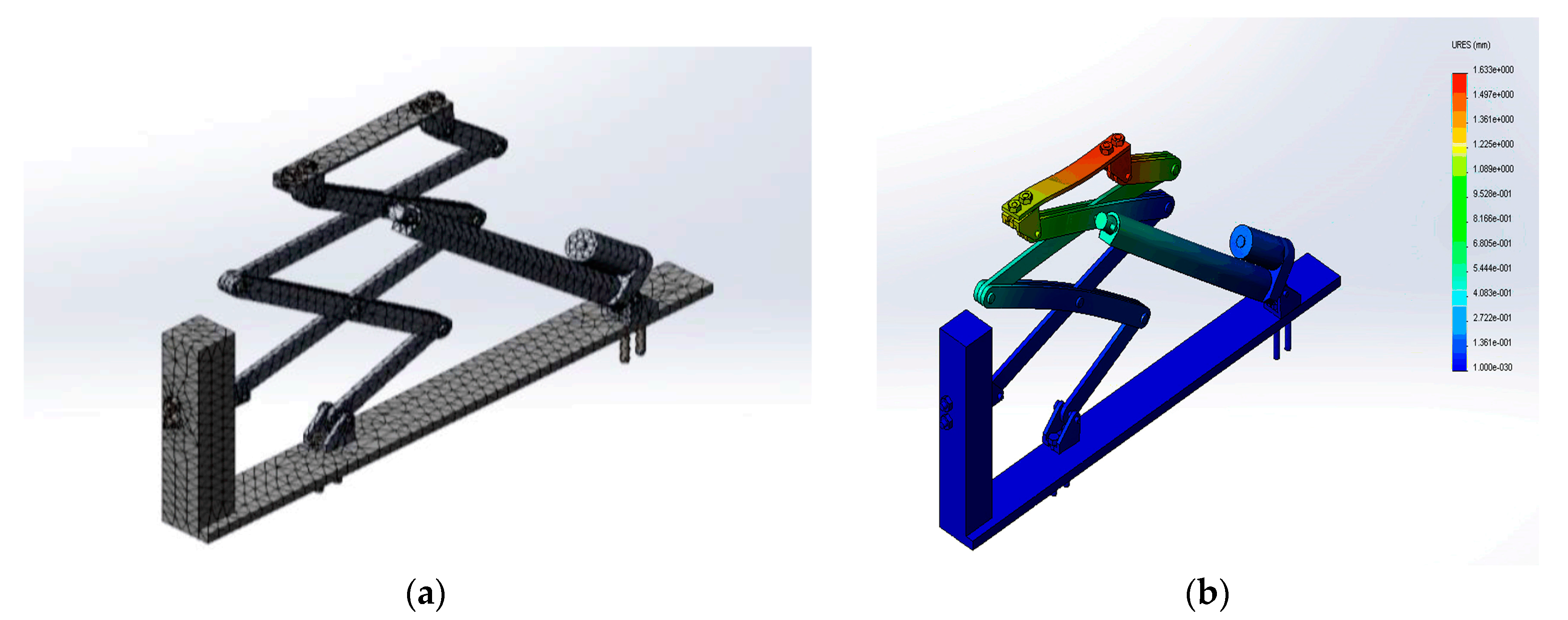
The support mechanism consists of a complex set of articulated parts that form a skeleton in the form of scissors. This structure makes it possible to ensure the transmission of the movement attributed by the force of the actuator. It consists mainly of aluminum bars fixed by stainless steel screws. The solver used in Solidworks was the direct solver, and the reason for this choice was to bind to the type of geometry. Indeed, the FFEplus solver is not recommended as it becomes less accurate than a direct solver in multi-material assemblies (Figure 9a). The safety factor varies according to the different types of mechanical linkage of the model, which has been confirmed for each specific case in this project. The maximum displacement shown in Figure 9b is 1.63 mm, and it is the fixing brackets in contact with the supports that will undergo the greatest displacement. The remainder of the structure will undergo almost zero displacement.
The following parameters are used in FEA analysis:
- Total number of nodes and elements are 46,946 and 22,896 respectively;
- Maximum aspect ratio is 23,658;
- Coefficient of friction is 1.9 × 10⁻¹
For the simulation of the assembly, the linear static study was chosen to analyze linear stresses loaded by static forces provided by the two actuators of 668 N each and a force 500 N also, which represents the weight of the person concentrated on the seat of the toilet.
5. Modeling of the Interactive System
The aim of this research is to provide assistance at home for a person with a loss of autonomy caused by an accident, following an operation, or as a result of aging. The automated mechanism is therefore not a system that completely replaces human function. It is rather designed to provide personalized assistance for rehabilitation. However, the system has to be automatic without any command from the user. This assistance must therefore be modulated according to the improvement of the performance of the human. The main objective of the control is therefore to determine the sequences of function that enable training (for example, reduce the applied force gradually). To ensure these functionalities, we define four basic states in sequence. These basic states represent the position of the toilet seat after each operation cycle. Figure 10 represents the displacement of the assistive system for a given period.
5.1. The Positions of the Seat for the Control Cycle are the Following
On this figure, the four states are,
- States A and C: the seat of the toilet is in the initial position;
- States B and D: the seat of the toilet is to the maximum position.
Since the system could be used as a rehabilitation system, the set point of the applied force has to be controlled. It is useful also to know the velocity of the seat and its position in order to evaluate the performance by a clinician. Then, the transitions (steps between each states A, B, C, and D) of the displacement of the assistive system are the following:
- The seat of the toilet rises to the maximum position (transition 1 from state A to B) while sensing the user near the toilet after a fixed delay in order to avoid false detection such as the user passing in the front of the toilet;
- The user sits down on the seat and is supported by the assistive system during the descent (transition 2, The force rendered to the user is controlled using the FSR force sensor as measurement;
- At the initial position in the state C, a minimal torque τmin is applied on the actuator in order to give a minimal force on the seat in order to detect the next transition condition;
- When the force sensor at the back location is under a threshold and the minimal force moves the seat, a detection of the stand-up occurs and is helped by the assistive system during the ascension (transition 3 from states C to D);
- When all the force sensors are under a threshold (the user is then not in contact with the seat), the seat returns to its initial position automatically (transition 4 from states D to A), meaning that the user does not need any help at this position;
- In state B, when there is not force measured by the four FSR (for a false detection in transition 1), the seat returns to its initial position automatically after 1 second (transition 5, from state B to A);
- In state C, if it seems that the user is not on the seat (for a low distribution of forces under a threshold), the seat returns to its initial state A automatically after 1 s (transition 6 from state C to A). This transition is only added to avoid deadlock (waiting indefinitely from the sensors measurement).
5.2. Closed-Loop Control Using an Admittance Model
The use of the closed loop system is our choice of design because it allows achieving a human-machine interaction, which promotes a personalized assistance and allows improving training by adapting the force rendered to the user. Inside the closed-loop control, it is possible to use an admittance model or an impedance model. The admittance model accepts a force in the input and generates a position (or velocity) which is the set point for a position (or velocity) feedback controller [27]. On the other hand, the impedance model accepts a position and generates a force to be controlled [27]. Since the control of the force needs a system with low inertia and low friction, we choose the admittance model. Of course, we have already the force sensor as an input and then we can control the position or the velocity with an encoder or a potentiometer. The position and velocity controller of the motor is a standard problem using a classical control law (usually a PI) and is not presented in this paper. Therefore, the admittance controller, adapted to the assistive mechanism, is presented in the following.
The second order differential equation of the system dynamic is represented by the following equation:
where fH is the total human force applied on the seat, mv, cv, kv are the virtual mass, damping, and stiffness felt by the user, respectively. Also, , , are the initial position, velocity, and acceleration of the seat, and x(t) and its derivative are the measurement. Since we do not want a force linked with the initial position, kv is set to zero (kv is related to a spring). Finally, the initial acceleration and velocity are both zero. Therefore, we have the following final equation:
We select to control the velocity of the seat, where we could find the transfer function given by
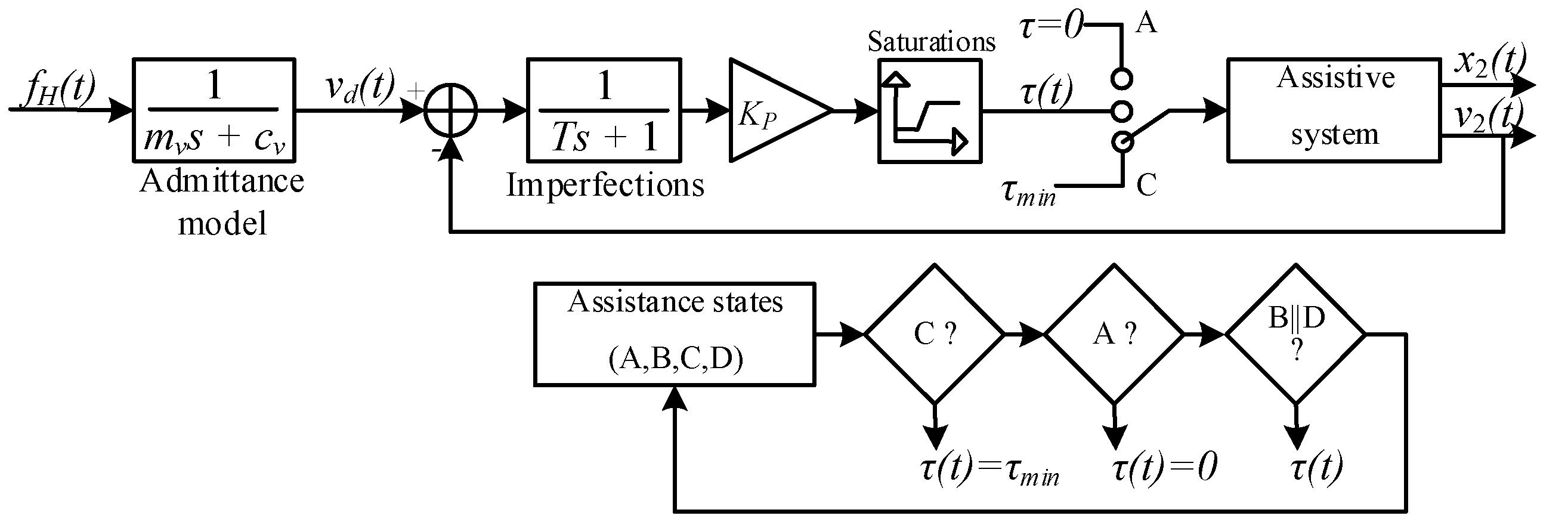
The uppercase letters represent the Laplace transform of lowercase variables. Vd(s) is the desired velocity. The velocity is then adjusted in function of the training program with the parameters mv and cv. Therefore, Figure 11 presents the feedback control used for this system, which is applied in each transition. τ(t), x2(t), and v2(t) are respectively the torque send to the motor, the measured position, and velocity of the seat. The torque is always limited by a minimal (state C, transition 3: τmin) and maximal value for safety, as described by a saturation bloc in Figure 11. The control loop also includes some imperfections coming from the errors in the values of the model parameters, overhead, and communication delay. These imperfections are modeled by a constant time T, which includes only a phase in the frequency domain (the gain is set to be one). Finally, we chose only a gain Kp for the control law of the admittance controller, since the integral term is not adapted for collaborative robotics, and the derivative term adds some noises that increase mechanical vibrations.
Figure 11 is very similar to the control loop for a cooperative robot such as that presented in [28] without the human arm stiffness in the outer feedback loop. As the position of the seat is not related to a desired position from the human, the model is in open-loop. Indeed, in collaborative robotic, the closed-loop is done by a visual feedback of the target position reached by the hand. In our device, this is not the case and only the force of the user is considered as a setpoint to the admittance model.
The assistive mechanism model could be represented by a first order transfer function with a gain of 0.1 and a constant time of 0.7 s. These values are obtained after an identification process with a Heaviside input. The final system including all transfer functions gives a third order transfer function that could be instable under some constraints. Since the admittance model is outside the feedback, only Kp could give an unstable system. The Routh-Hurwitz criterion can give the limit of the gain loop Kp. By the inspection of the model, the gain loop will never destabilize the response since the second order system in the feedback loop gives always negative poles for all gain loops.
6. Results and Discussion
6.1. Sensors Responses
In order to activate the mechanism by the transition between A and B states, a threshold is applied on the IR range sensor. The user should be in the front of the toilet inside a range between 10 and 60 cm over 3 s. This allows the system to ensure that the user intends to use the toilet before sending a signal to the admittance controller. The maximal distance and the time are adjusted with a first order Butterworth low-pass filter. This filter is applied on the IR range sensor and potentiometer signals with the same time constant, around 2 s. Figure 12a shows the superposition of the two responses of the IR range sensor and of the potentiometer where the timing is shown.
In Figure 12b, a test was carried out on the mechanism in order to inject the signal sent by the force sensors in the form of an electrical voltage as an input of the mass in pounds of the person sitting on the toilet seat. The output represents the force provided by the sensors to ensure balance of the forces. The force applied by the person on the toilet seat is converted by the four force sensors into a voltage-normalized signal and then converted in a local COP vector (barycenter) in order to provide a single resultant vector. This vector allows the system to recognize the exact force or mass of the person sitting on the seat, and provide a velocity through the admittance controller to ensure balance. On this figure, the damped oscillation, around 330 Hz, is generated by the mechanical structure when the human touch the seat. This input is used to simulate all the parameters used for the admittance controller presented in the next section.
6.2. Admittance Controller Simulations
The setpoint of the admittance model was measured with an experiment in all the following simulations. The parameters mv, cv, and Kp are evaluated in order to understand the impact of them on the output. The user weight was 45 kg and the imperfection on the model is evaluated as a constant time of 0.08 s. Initial values of mv, cv and Kp are chosen to be 10 kg, 120 Ns/m and 50, respectively. These values give 56.3 dB at 16.6 rad/s for the gain margin and an infinite phase margin, suggesting that this system is always stable and then it will be limited by the saturation of the actuator and amplifier.
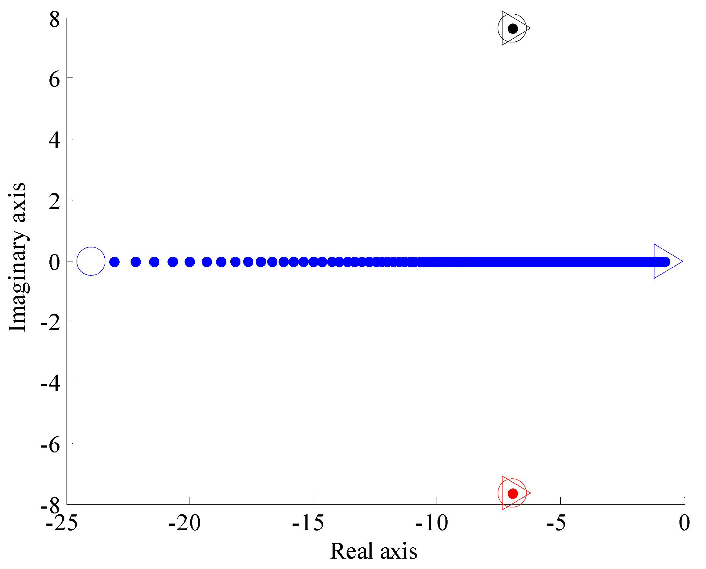
First, the most important parameter is the virtual mass mv felt by the user while seating or standing. In a training program, this virtual mass could be reduced or increased depending on the capacity of the user. The choice for the value of the virtual mass is not in the scope of this paper since it needs a clinical evaluation with person with loss of autonomy. The location of the poles for a virtual mass varying from 5 to 150 kg is shown in Figure 13 (this is neither a root locus nor an Evan locus). The simulation finds the root of the transfer function for each virtual mass. As we have three poles in our transfer function, three colors are used in the following Figure 13, Figure 14 and Figure 15. The admittance model is outside the inner loop, and then there is a pole located at the position cv/mv. This pole moves following the blue line in Figure 13, Figure 14 and Figure 15. The inner loop generates the black and red poles. The effect of the gain loop is shown in Figure 15.
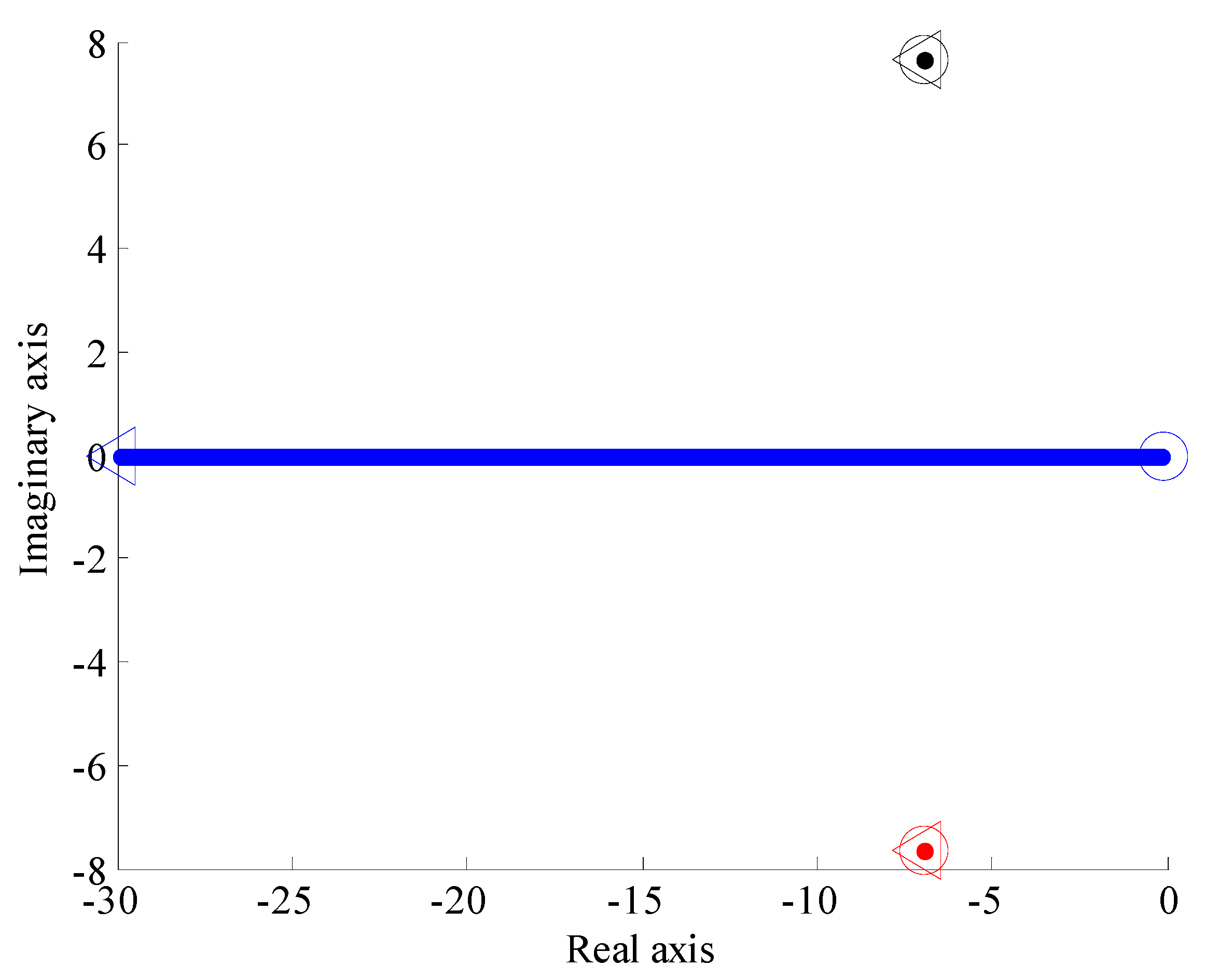
This mass is felt as a force applied to the user in the acceleration phase. Thereafter, the virtual damping is also evaluated in Figure 14. The virtual damping is difficult to apply in a training program and is much more related to the user preference. This virtual damping is associated to a force acting against the direction of the velocity of the seat. Therefore, it could be seen as a factor on the seat reaction. It provides a constant force for a constant velocity.
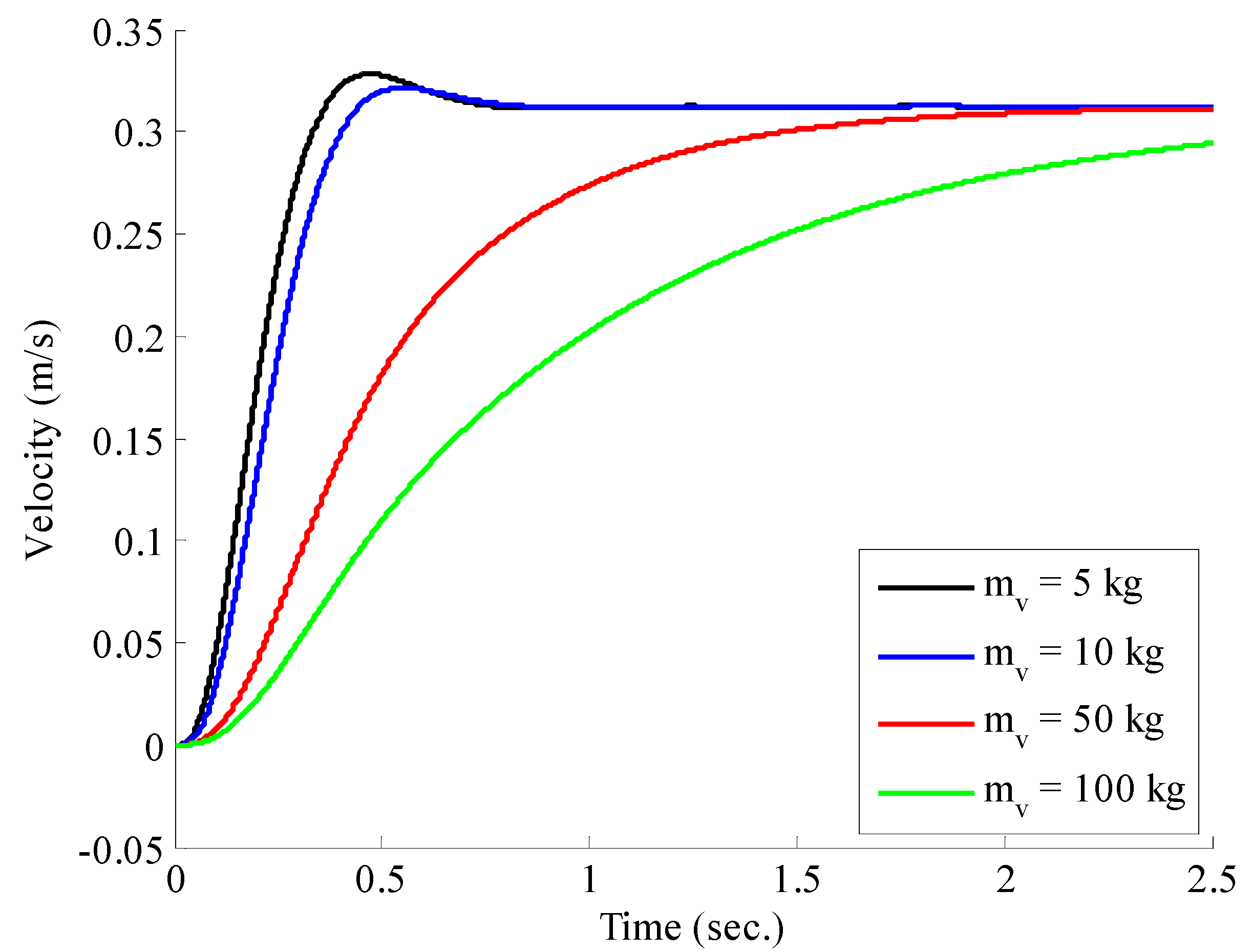
Finally, the effect of the gain loop on the model is shown in Figure 15. This gain should be set high, as much as possible, just before the saturation limits of the amplifier and the actuator. This gain is adjusted for the accurate rendering of both virtual mass and damping previously selected. For a gain loop fixed at 50, Figure 16 shows the output velocity of the seat, while the setpoint in Figure 12b is sent to the admittance model. The impact of the felt virtual mass is clear on the velocity of the seat: when the virtual mass increases, the velocity is reduced for the same input, meaning that the user is more supported by the seat. Therefore, the user gets more assistance with higher virtual mass as suggested by the collaborative model. This virtual mass should then be used to adjust the assistance in a training program.
7. Conclusions
The main objective of this project was to design an assistive system personalized to help person with a loss of autonomy. It was possible to achieve the specific objectives, which were to prevent falls of users in the bathroom. A prototype was manufactured and assembled according to the specifications of a standard usage. This step confirmed the validity of the design and the controller of the mechanism. It was then possible to compute the load of the internal forces and to validate the results obtained by a study of finite elements. In terms of control, the system shows stable response for a virtual mass varying from 5 to 150 kg as shown in Figure 13 and Figure 14 where the feedback loop gives negative poles for all gain loops. Accordingly, the gain loop will never destabilize the response. In addition, in Figure 16, it was clear that the output velocity of the seat is reduced when the virtual mass increases, which means that the user gets more assistance by the mechanism with higher virtual mass, as suggested by the collaborative model.
A limitation of this study is the small sample size, which was obtained using a single participant. Although our results suggest that the proposed technology can be used successfully to help a person with a balance disorder, testing on a larger dataset with multiple participants would help to further validate recordings.
Future research can also include a physiotherapist. The physiotherapist may adjust the parameters of the admittance controller with some trials with the participant and try to adjust the system to its best experience. However, it could be possible to give an index in order to help the decision of the physiotherapist. Therefore, in order to plan a training program, a physiotherapist could use clinical evaluation of balance and risk of fall. These tests could be the Timed-Up-and-Go (TUG), the Breg Balance Scaled (BBS), or Tinetti tests, among others. The score obtained from these tests could be linked to the admittance controller by a function which could give an index. Then, depending the score accorded to these tests, it could be possible to adjust the assistance with the virtual mass using this index. This link between the clinical test and the admittance controller is of course not yet complete and requires an experiment with participants with a history of falling (or with a loss of autonomy) and all the apparatus necessary for safety. For a person in the process of rehabilitation, the virtual mass should be reduced progressively until the interactive system no longer gives any help. The reduction and variation of the virtual mass are still unknown and should be evaluated with participants.
Acknowledgments
This work is supported by the financial support of the Natural Sciences and Engineering Research Council of Canada (NSERC) under grant number 418235-2012.
Author Contributions
E.J. and A.A. conceived of and designed the prototypes, performed the experiments, and analyzed the data. M.O. (research director of E.J., A.A. and K.Y.) contributed reagents/materials/analysis tools and designed, simulated, and analyzed all the section related to the admittance controller. E.J., A.A., K.Y., and M.O., wrote and revised the paper. M.O. holds the grant from NSERC.
Conflicts of Interest
The authors declare no conflict of interest. The founding organization (NSERC) had no role in the design of the study; in the collection, analyses, or interpretation of data; in the writing of the manuscript, and in the decision to publish the results.
References
- Ministere de la Famille et Des Aines (2012). Vieillir et Vivre Ensemble. Available online: https://www.mfa.gouv.qc.ca/fr/publication/Documents/politique-vieillir-et-vivre-ensemble.pdf (accessed on 10 October 2017).
- Canadian Institute for Health Information. Health Care in Canada (2011). Available online: https://secure.cihi.ca/free_products/HCIC_2011_seniors_report_en.pdf (accessed on 10 October 2017).
- Schlebusch, T. Unobtrusive Health Screening on an Intelligent Toilet Seat. Acta Polytech. 2011, 51, 94–99. [Google Scholar]
- Stevens, J.A.; Haas, E.N.; Haileyesus, T. Nonfatal bathroom injuries among persons aged ≥ 15 years—United States, 2008. Morb. Mortal. Wkly. Rep. 2011, 60, 729–733. [Google Scholar]
- Scott, V.; Pearce, M.; Pengelly, C. Technical Report: Injury Resulting from Falls among Canadians Age 65 and over, in Report on Seniors’ Falls in Canada; Public Health Agency of Canada: Ottawa, ON, Canada, 2005; pp. 1–16. [Google Scholar]
- Span, P. The most dangerous room in the house. New York Times, 28 May 2009. [Google Scholar]
- Camirand, J.; Fournier, C. Vieillir en Santé au Québec: Portrait de la Santé des Aînés Vivant à Domicile en 2009–2010, in Zoom Santé; Institut de la Statistique du Québec: Québec, QC, Canada, 2012; pp. 1–12. [Google Scholar]
- Magnusson, C.; Alm, N.; Edelmayer, G.; Mayer, P.; Panek, P. Rapid prototyping of interface and control software for an intelligent toilet. Assist. Technol. Res. Ser. 2011, 27, 101–111. [Google Scholar]
- Panek, P.; Edelmayer, G.; Magnusson, C.; Mayer, P.; Molenbro, J.F.; Neveryd, H.; Schlathau, R.; Zagler, W.L. Investigations to develop a fully adjustable intelligent toilet for supporting old people and persons with disabilities—The friendly rest room (FRR) project. In Lecture Notes in Computer Science (Including Subseries Lecture Notes in Artificial Intelligence and Lecture Notes in Bioinformatics); Springer: Berlin/Heidelberg, Germany, 2004; pp. 392–399. [Google Scholar]
- Buzink, S.N.; Bruin, R.D.; Groothuizen, T.J.J.; Haagsman, E.M.; Molenbroek, J.F. Fall prevention in the toilet environment. Assist. Technol. Res. Ser. 2011, 27, 183–193. [Google Scholar]
- Gibbons, F.B. Power Assisted Toilet Seat. U.S. Patent US 4,993,085 A, 19 February 1991. [Google Scholar]
- Buzink, S.N.; Molenbroek, J.F.; Haagsman, E.M.; Bruin, R.D. Falls in the toilet environment: A study on influential factors. Gerontechnology 2005, 4, 15–26. [Google Scholar] [CrossRef]
- Dekker, D.; Buzink, S.N.; Molenbroek, J.F.; Bruin, R.D. Hand supports to assist toilet use among the elderly. Appl. Ergon. 2007, 38, 109–118. [Google Scholar] [CrossRef] [PubMed]
- Panek, P.; Edelmayer, G.; Mayer, P.; Zagler, W.L. Laboratory tests of an adjustable toilet system with integrated sensors for enhancing autonomy and safety. Assist. Technol. Res. Ser. 2011, 27, 151–165. [Google Scholar]
- Groothuizen, T.J.J.; Rist, A.; Weeren, M.H.V.; Dekker, D.; Bruin, R.D.; Molenbroek, J.F. The final FRR components. Assist. Technol. Res. Ser. 2011, 27, 112–123. [Google Scholar]
- Liaskos, J.; Mantas, J. Technologies of smart toilets for the elderly and people with disabilities: The friendly rest room project. J. Inf. Technol. Healthc. 2005, 3, 315–322. [Google Scholar]
- Imbeault-Nepton, T.; Otis, M.J.-D. Synchronized walking cadence for TUG in perturbed environments: Using Earcon or Tacton cues? In Proceedings of the 2014 IEEE International Symposium on Haptic, Audio and Visual Environments and Games (HAVE), Richardson, TX, USA, 10–11 October 2014; pp. 41–46. [Google Scholar]
- Ayena, J.C.; Zaibi, H.; Otis, M.J.-D.; Ménélas, B.-A.J. Home-Based Risk of Falling Assessment Test Using a Closed-Loop Balance Model. IEEE Trans. Neural Syst. Rehabil. Eng. 2016, 24, 1351–1362. [Google Scholar] [CrossRef] [PubMed]
- Duchaine, V.; Gosselin, C. Unified robot control scheme for cooperative motion, autonomous motion and contact reaction. J. Robot. Mechatron. 2011, 23, 557–566. [Google Scholar] [CrossRef]
- Duchaine, V.; St-Onge, B.M.; Gao, D.; Gosselin, C. Stable and intuitive control of an intelligent assist device. IEEE Trans. Haptics 2011, 5, 148–159. [Google Scholar] [CrossRef] [PubMed]
- Tarik, M.; Bouchard, B.; Bouzouane, A. Unsupervised Activity Recognition using Temporal Data Mining, in International Conference on Smart Systems. In Devices and Technologies; IARIA: Stuttgart, Germany, 2012; pp. 1–8. [Google Scholar]
- Panek, P.; Dayé, C.; Edelmayer, G.; Gentile, N.; Groothuizen, T.; Mayer, P.; Rauhala, M.; Rist, A.; Schlathau, R.; Zagler, L.W. Real Life Test with a Friendly Rest Room (FRR) Toilet Prototype in a Day Care Centre in Vienna—An Interim Report. Presented at AAATE Conference, Lille, France, 6–9 September 2005; pp. 1–5. [Google Scholar]
- Panek, P.; Neveryd, H.; Zagler, W.L. The FRR project: Developing a more user friendly rest room; presentation: AAATE’03, Dublin; 08-30-2003-09-03-2003. In Assistive Technology—Shaping the Future; Craddock, G., McCormack, L., Reilly, R., Knops, H., Eds.; IOS Press: Dublin, Ireland; pp. 678–682.
- Australia Hunter. Portable Electric Hydraulic Johnny Aid. U.S. Patent 3,925,833, 8 March 1974.
- Capteur De Distance Infra-Rouge (Sharp). Pobot.org. Available online: www.pobot.org/IMG/article_PDF_Capteur-IR-Sharp-GP2D120.pdf (accessed on 18 October 2008).
- Huston, R.L. Principles of Biomechanics; CRC Press: Boca Raton, FL, USA, 2009. [Google Scholar]
- Carignan, C.; Cleary, K. Closed-loop force control for haptic simulation of virtual environments. Haptics-e Electron. J. Haptics Res. 2000, 1, 1–14. [Google Scholar]
- Campeau-Lecours, A.; Otis, M.; Gosselin, C. Modeling of physical human–robot interaction: Admittance controllers applied to intelligent assist devices with large payload. Int. J. Adv. Robot. Syst. 2016, 13, 1–12. [Google Scholar] [CrossRef]
Figure 1.
Configuration of the retained geometry for the intelligent seating assist toilet: the bars are identified with numbers and the joints by letters.
Figure 1.
Configuration of the retained geometry for the intelligent seating assist toilet: the bars are identified with numbers and the joints by letters.

Figure 2.
(a) Assistive system installed on the toilet final prototype; (b) Assistive system installed on the toilet designed in SolidWork.
Figure 2.
(a) Assistive system installed on the toilet final prototype; (b) Assistive system installed on the toilet designed in SolidWork.

Figure 3.
Localization of the sensors: (a) four FSR402 sensors; (b) IR range sensor located in the front.
Figure 3.
Localization of the sensors: (a) four FSR402 sensors; (b) IR range sensor located in the front.

Figure 4.
Electronic connection diagram.

Figure 5.
Pi location of the center of pressure on the sole in both directions.

Figure 6.
Optimization of the mechanism geometry with the trajectory.

Figure 7.
Desired trajectory to follow for the mobile seat.

Figure 8.
Optimized path (black circle) obtained by the Synthesis and Analysis of Mechanisms (SAM) software in the (a) initial position and (b) final position for the desired trajectory represented.
Figure 8.
Optimized path (black circle) obtained by the Synthesis and Analysis of Mechanisms (SAM) software in the (a) initial position and (b) final position for the desired trajectory represented.

Figure 9.
(a) Volumetric mesh for the deformation simulation under two force constraints: two actuators of 668 N each and a force 500 N; (b) Displacements results where red and blue colors represent a displacement of 1.6 mm and 0 mm, respectively.
Figure 9.
(a) Volumetric mesh for the deformation simulation under two force constraints: two actuators of 668 N each and a force 500 N; (b) Displacements results where red and blue colors represent a displacement of 1.6 mm and 0 mm, respectively.

Figure 10.
Diagram of the state machine (operating cycle) of the assistive system.

Figure 11.
Control loop system with the selection of the torque to apply on the actuator.

Figure 12.
(a) Superposition of the two responses of the potentiometer and the proximity sensor (b) response of the force sensor submitted to the admittance model.
Figure 12.
(a) Superposition of the two responses of the potentiometer and the proximity sensor (b) response of the force sensor submitted to the admittance model.

Figure 13.
Location of the poles for the assistive toilet system for a virtual mass mv varying from 5 kg (circle) to 150 kg (triangle), cv = 120 Ns/m, T = 0.08 s, Kp = 50.
Figure 13.
Location of the poles for the assistive toilet system for a virtual mass mv varying from 5 kg (circle) to 150 kg (triangle), cv = 120 Ns/m, T = 0.08 s, Kp = 50.

Figure 14.
Location of the poles for the assistive toilet system for a virtual damping cv varying from 1 Ns/m (circle) to 300 Ns/m (triangle), mv = 10 kg, T = 0.08 s, Kp = 50.
Figure 14.
Location of the poles for the assistive toilet system for a virtual damping cv varying from 1 Ns/m (circle) to 300 Ns/m (triangle), mv = 10 kg, T = 0.08 s, Kp = 50.

Figure 15.
Location of the poles for the assistive toilet system for a gain loop Kp varying from 1 (circle) to 100 (triangle), cv = 120 Ns/m, T = 0.08 s, mv = 10.
Figure 15.
Location of the poles for the assistive toilet system for a gain loop Kp varying from 1 (circle) to 100 (triangle), cv = 120 Ns/m, T = 0.08 s, mv = 10.

Figure 16.
Response of the seat velocity for a varying virtual mass mv, cv = 120 Ns/m, T = 0.08 s, Kp = 50.
Figure 16.
Response of the seat velocity for a varying virtual mass mv, cv = 120 Ns/m, T = 0.08 s, Kp = 50.

© 2017 by the authors. Licensee MDPI, Basel, Switzerland. This article is an open access article distributed under the terms and conditions of the Creative Commons Attribution (CC BY) license (http://creativecommons.org/licenses/by/4.0/).
Share and Cite
MDPI and ACS Style
Otis, M.J.-D.; Adjelane, A.; Jomphe, E.; Youssef, K. Toilet Assistive System Designed for the Reduction of Accidental Falls in the Bathroom Using Admittance Controller. Machines 2017, 5, 23. https://doi.org/10.3390/machines5040023
AMA Style
Otis MJ-D, Adjelane A, Jomphe E, Youssef K. Toilet Assistive System Designed for the Reduction of Accidental Falls in the Bathroom Using Admittance Controller. Machines. 2017; 5(4):23. https://doi.org/10.3390/machines5040023
Chicago/Turabian StyleOtis, Martin J.-D., Abid Adjelane, Eric Jomphe, and Khaled Youssef. 2017. "Toilet Assistive System Designed for the Reduction of Accidental Falls in the Bathroom Using Admittance Controller" Machines 5, no. 4: 23. https://doi.org/10.3390/machines5040023
Note that from the first issue of 2016, this journal uses article numbers instead of page numbers. See further details here.