
Abstract
Spin pumping has become an established method for generating voltages using magnetic dynamics. The standard detection method of spin pumping is based on open-circuit voltage measurement. In this study, we demonstrate that it is also possible to measure the associated electric current by using macroscopic closed circuitry. Using variable load resistors connected in series to the sample, we quantified the charge currents and associated electric power dissipation with respect to the load resistance. Through basic circuit analysis, we can describe spin-pumping cells as a non-ideal voltage source or an equivalent current source with an internal resistor.
Export citation and abstract BibTeX RIS

Content from this work may be used under the terms of the Creative Commons Attribution 4.0 license. Any further distribution of this work must maintain attribution to the author(s) and the title of the work, journal citation and DOI.
This article was made open access on 13 February 2018.
Spin currents, i.e., the flow of angular momentum without the simultaneous transfer of electrical charge, play a pivotal role in the current developments of spintronic research. For example, they can be used to manipulate magnetic dynamics,1) switch magnetic moments,2) and facilitate spintronic energy-harvesting applications.3) The generation of spin currents has been widely explored in the last decade.4) Through the inverse spin Hall effect (ISHE),5) charge currents can be converted into a spin current that flows perpendicular to the charge flow orientation, and a wide range of thin-film metallic and semiconducting materials have been examined for the efficient generation and detection of spin currents through the SHE.6–8) Another widely used method for generating spin currents is spin-pumping using magnetic dynamics.9) When the magnetic dynamics are driven by microwave (MW) absorption of a ferromagnetic (FM) material, non-equilibrium spin waves are accumulated and dissipated at a fixed rate. One of the dissipation mechanisms in a FM/non-magnetic (NM) bilayer involves the transfer of angular momentum to electron spins in the NM layer, where spin currents are generated. The spin currents are then converted into charge currents through the ISHE, as illustrated in Fig. 1(a). High-spin orbit materials such as Pt are often used as good SHE materials for the efficient detection of the spin currents. Although this is an electric charge–current excitation picture, the commonly used circuitry for spin-pumping measurements is based on an open circuit, where the electric voltages are measured and discussed as a signature of spin pumping and the ISHE.

Fig. 1. (a) Schematic of spin-pumping and the ISHE mechanism in an FM and NM bilayer sample. (b) FMR spectra measured at a frequency of 4 GHz and 20-mW MW power using AC-modulation techniques. (c) Voltage (Vopen) measured across the sample for different powers. The results for both the positive (solid lines) and negative (dashed lines) magnetic-field directions are shown, for comparison. The measurement MW frequency was 4 GHz, and the magnetic field was applied perpendicular to the voltage measurement direction in-plane. (d) MW excitation power dependence of the voltage peak height ΔVopen (dot) with a linear fit line (solid curve).
Download figure:
Standard image High-resolution imageIn this paper, we introduce a charge current detection method for spin pumping in a macroscopic closed circuit. In this scheme, instead of using an open circuit, we close the circuit with a load resistor, which allows us to measure the generated charge current in a spin-pumping device using the ISHE. We thereby measure the electric power transfer from the spin-pumping device into the external load resistor, which was not much discussed previously. Furthermore, our basic circuit analysis indicates that a non-ideal voltage (or equivalent current) source model can describe spin-pumping devices. According to this analysis, the maximum power transfer, internal resistance, and ISHE current for the devices were evaluated and discussed. This type of analysis has not been widely employed — only very recently in a spin-Seebeck experiment10)—and has not been used particularly for spin-pumping experiments using FM resonance (FMR). A similar charge-detection method for measuring the ISHE was reported by Omori et al.11) However, in contrast to our study, their devices are a microfabricated closed circuit, where spin-currents were generated through an electrical spin-injection method. Our study demonstrates the wide applicability of the closed-loop circuit measurements for spin pumping, as it is not limited to lithographically patterned nanoscale devices but is also applicable to macroscopic spin-pumping devices for which no microfabrication steps are needed.
Pt (5 nm)/Ni81Fe19 (5 nm) bilayers were grown via direct-current (DC) magnetron sputtering onto thermally oxidized single crystal silicon substrates 5 × 5 mm2 in area under Ar at 1.5 Pa in an ultrahigh vacuum system with a base pressure better than 10−9 mBar. The layer thicknesses were controlled by changing the deposition power and rotating the substrates below stationary magnetrons. After the growth, the samples were placed face-down on a coplanar waveguide board to maximize the oscillating magnetic-field strength, and an insulating ultrathin tape was inserted between the sample and the MW board. Two electrodes were attached at both ends of the sample chips, allowing electrical detection of the ISHE. For ISHE measurements, we pulse-modulated the MW to increase the sensitivity. We measured the FMR MW absorption in our sample via alternating-current (AC) magnetic-field modulation techniques using an MW power detector. In Fig. 1(b), we observe a clear FMR peak around 30 mT at an MW frequency of 4 GHz. Note that the differential form of a Lorentzian curve has been measured using AC modulation techniques. We then measured the voltage across the sample (Vopen) while sweeping the same magnetic-field region and observed Lorentzian-type peaks, as shown in Fig. 1(c). Consistent with the symmetry of the electric field generated by the ISHE (EISHE ∝ σ × Js), a sign change was observed in VISHE when the magnetic-field polarity was reversed; here, σ is the spin polarization direction, and Js is the spin current flow orientation. The MW power dependence of the peak voltage (ΔVopen) is plotted in Fig. 1(d), confirming that the dependence follows a standard model of spin-pumping in the linear regime.12) There might be other voltage components within ΔVopen that we quantified, such as spin rectification voltages arising from the planar Hall effect that in theory appears in the Lorentzian lineshape.13,14) A clear separation between these voltages and the ISHE one is difficult; thus, in general, we treat ΔVopen as a voltage generated by spin precession.
To extract electric power from spin pumping, we used a variable load resistor to close the open-circuit configuration, as shown in Fig. 2(a). This allowed the pumped charge currents in the sample to flow in the closed circuit; thus, finite power dissipation occurred in the load resistor, which can be measured according to the voltage drop across the load resistor. Figure 2(b) plots the voltage drop (Vload) for different load resistors. The voltage across the resistor is small at low load-resistance (Rload) values and increases with Rload. The plot of the voltage amplitude (Vpeak) with respect to Rload in Fig. 2(c) reveals the gradual growth of Vpeak towards the open-circuit voltage (Vopen) in the high-resistance regime. We repeated the same experiments for different MW powers, confirming the same dependence. Using this voltage, Vpeak, and the known value of Rload for each measurement, we calculated the charge current flowing across the load resistor (Iload) and plotted it, as shown in Fig. 3(a). Likewise, the dissipated power across the load resistors (Pdis) was calculated using Pdis = IloadVload and is plotted in Fig. 3(b). We observe that Pdis peaks at a finite Rload and tends to zero for both the smallest and highest load-resistance limits.

Download figure:
Standard image High-resolution image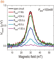
Download figure:
Standard image High-resolution image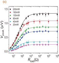
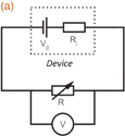
Fig. 2. (a) Schematic of the closed-circuit measurement setup used for this study. We measured voltage drops across a variable resistor (Vload) placed in series with the spin-pumping device. The magnetic field was applied perpendicular to the voltage measurement direction in-plane. (b) Measurement of Vload for different load resistor values (Rload). The MW power was 100 mW. (c) Peak amplitude (Vpeak) of Vload for different Rload and MW powers. The solid curves are the best-fit ones from theoretical calculations (see the main text).
Download figure:
Standard image High-resolution image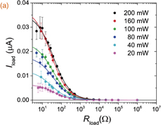
Download figure:
Standard image High-resolution image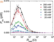
Fig. 3. Load-resistance (Rload) dependence of (a) the electric current (Iload) and (b) the dissipated power (Pdis) across the resistors, for different MW powers. The experimental data represented by dot and solid curves are from bet-fit results obtained using theory (see the main text).
Download figure:
Standard image High-resolution imageThese results from the closed-circuit experiments can be understood according to a non-ideal voltage source model, as shown in Fig. 4(a). A non-ideal voltage source includes an internal resistor to self-dissipate power. When the internal resistor is connected in series to Rload, the (fixed) pumped voltage must be distributed into the two resistors, each of which dissipates electric power. This series resistor circuit acts as a potential divider, and Vload can be expressed as
where Ri is the internal resistance. This equation reproduces the Rload dependence of our observed voltage Vpeak, which is shown as solid curves in Fig. 2(c). The charge current and dissipated power in the load resistors can be calculated by using Ri and Vopen as follows:

Pdis has a peak value of  when Rload = Ri; this is the maximum-power transfer condition, which is frequently observed and discussed in standard electronics such as radio transmitters and high-frequency amplifiers.15) Using the above theoretical formulae, we fit our experimental data [solid lines in Figs. 2(c), 3(a), and 3(b)] with Ri as the only fitting parameter. Despite the wide range of Rload (6 orders of magnitude), all best-fit results can be produced with Ri very close to the measured sample resistance of 29 Ω (see Table I). From this, we can conclude that there exists an internal resistance in the samples during the spin-pumping experiments, which should be considered when one tries to transfer electric power from a spin-pumping device to an external load resistor.
Download figure:
Standard image High-resolution image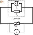
Fig. 4. Circuit diagrams representing spin-pumping/ISHE experiments performed for this study, with the ISHE cell being modeled as (a) a non-ideal voltage or (b) a non-ideal current source.
Download figure:
Standard image High-resolution image
Table I. Internal resistance (Ri) extracted from simultaneous fits to Vpeak, Iload, and Pdis data for each measurement with the MW power ranging from 20 to 200 mW.
| MW power (mW) | Ri (Ω) |
| 20 | 38.2 |
| 40 | 28.8 |
| 80 | 40.2 |
| 100 | 36.8 |
| 160 | 29.0 |
| 200 | 38.1 |
We can also consider the spin-pumping device cell as a non-ideal current source. The transformation of a voltage source into an equivalent current source is possible through Thevenin–Norton circuit analysis.16) According to Norton's theorem, any network of batteries and resistors having two output terminals can be replaced by the parallel combination of a current source and a resistor. Figure 4 shows the two equivalent circuits describing the spin-pumping experiments, where the current source value can be determined as follows: I0 = V0/Ri. Using the current source model, where the load and internal resistors are connected in parallel, we can also write Vload as
This equation with the current source explains measured voltages such as Vpeak in Fig. 2(c) very well — for a small Rload, the prefactor of RloadRi/(Rload + Ri) remains small, meaning that Vpeak in the experiment should be small, whereas Vpeak gradually increases with increasing Rload, eventually approaching the value of Vopen for Rload = ∞ (open-circuit condition).
Finally, we discuss a phenomenological model that takes into account the conversion of MW energy into magnetic energy and then that of magnetic energy into electrical energy. Using the data in Fig. 1(a), the known modulation MW field amplitude (hmod), the equation Vdiode-dc = (1/hmod)∫Vlock-in(H) dH (where Vdiode-dc is the calculated DC response in the diode detector), and the diode voltage–power conversion ratio, we calculated the MW absorption peak for the FMR and estimated the peak height as 4 mW for 200-mW measurements. Compared with 14 fW, which is the highest electric power measured for the same MW insertion, we have a significant loss (a factor of 3.5 × 10⁻¹²) in energy transfer between the MW absorption into electric power generation in the load resistor. This lossy system can be readily understood; magnetic dynamics are in general very lossy, as a considerable amount of excited angular momentum (and energy) is constantly damped into the lattice. In addition, the spin-pumping process extracts a fraction of the non-equilibrium angular momentum into the conduction electron spin system in the adjacent NM layer, which depends strongly on the efficiency of spin coupling at the interface, i.e., the mixing conductance. A phenomenological model of spin pumping17–19) can indicate that the energy-transfer ratio is proportional to  , which reflects on the discussions above; here,
  is the real part of the mixing conductance,20) and α is the Gilbert damping parameter. Therefore, layer structures with a better damping material and a higher mixing conductance can yield better energy transfer in spin-pumping measurements.
In summary, we show that it is possible to measure an electric charge current generated by spin pumping and the ISHE by using a macroscopic closed-circuit detection method. Using variable load resistors, we can quantify the electric power generated by spin pumping and successfully transfer magnetic energy into electrical energy. We applied basic circuit analysis to our results and found that spin-pumping cells can be described using a non-ideal voltage source or an equivalent current source, whose internal resistance is very close to the measured device resistance.
Acknowledgment
This work was supported by the EPSRC through Programme Grant EP/N017242/1.