

Abstract
Quantum repeaters are required for realizing long-distance quantum communication. The quantum repeater consists of a quantum memory to store quantum information and an interface between photonic flying qubits and the memory qubits. Electron spins in gate-defined quantum dots (QDs), which have a relatively long coherence time and high electrical tunability, are promising candidates for such memory qubits because the fundamental technologies of detecting and manipulating single photoelectron spins have been established. The remaining challenge for the realization of quantum repeaters is an efficient coupling between photons and electron spins in the QDs. In this study, we discuss the enhancement of the transmission and the maintenance of the incident light polarization through bull's eye structures on gate-defined QDs on the basis of electromagnetic field simulations.
Export citation and abstract BibTeX RIS
1. Introduction
Quantum communication promises a completely secure communication system based on the no-cloning theorem of quantum mechanics. The communication distance is, however, limited to approximately 100 km in the case of conventional optical fiber networks. Therefore, quantum repeaters are needed to extend the communication distance. The repeaters consist of quantum memory qubits and a quantum interface between the photon flying qubits and the memory qubits. Electron spins in gate-defined lateral quantum dots (QDs), which have a relatively long spin coherence time and high electrical tunability, have been extensively studied for quantum computing1–4) and may provide a suitable platform for the quantum repeaters.5)
At the quantum interface, photon polarization states need to be coherently converted to electron spin states. A scheme for implementing this coherent conversion has been proposed utilizing semiconductor quantum wells (QWs).6) In this scheme, the excitation of a Zeeman-split light-hole state and both up and down electron spin states enables the transfer of photon polarization superposition states to electron spin superposition states. To realize this process, the spectral width (δħωp) of the excitation photon should be larger than the Zeeman splitting of the electron state ( ) and smaller than that of the light-hole state (
 ).
).  and
and  are the in-plane g-factors of the electron and the light hole, respectively. μB is the Bohr magneton. B∥ is the magnetic field applied parallel to the QW plane and orthogonal to the light propagation direction. These conditions can be fulfilled in QWs with appropriately engineered structures. This conversion scheme has been demonstrated in an ensemble manner by measuring the time-resolved Kerr rotation of photoelectron spins.7) In the quantum repeaters, this scheme has to be verified between single photons and single electron spins.
Some key technologies for the coherent conversion in QDs have already been developed. A quantum point contact (QPC) offers a very sensitive charge sensor to detect the charge and spin of single electrons confined in nearby QDs. By this technique, the detection of single photoelectrons8–12) and their spins13) in the QDs has been demonstrated. However, the excitation efficiency of electrons in a lateral QD was as low as 1% for light-hole excitation.12) This is mainly attributed to the low optical density of the thin QW layer. Moreover, the total conversion efficiency from incident photons to electrons is significantly suppressed owing to the mismatch between the beam spot size of light and the aperture size of the optical metal mask, which covers around the QD and the QPC to avoid the disturbance of the electrostatic environment caused by light irradiation. The diameter of the laser beam focused on the sample surface is approximately 10 µm, while the size of the aperture on the QD is 400 nm. Consequently, only about 10−3% of the photons impinging on the optical mask can excite an electron in the QD. For the future application to quantum repeaters, the conversion efficiency must be significantly improved. We also emphasize that the scheme used to enhance the conversion efficiency should preserve the incident photon polarization.
The objective lens of a microscope combined with a solid immersion lens is one way of reducing a laser beam spot size to less than 1 µm. Therefore, such a focusing system should be constructed in a dilution refrigerator with a microwave circuit, which is usually used for the stable manipulation of electron spins in gate-defined QDs. A few studies on the precise positioning of a focused laser beam spot in a dilution refrigerator with a superconducting magnet have been reported,14,15) suggesting the potential feasibility of precisely matching the beam spot to the aperture on a gate-defined QD placed in a dilution refrigerator.
Another way to achieve this is to utilize a bull's eye structure, which is a metal thin film consisting of a sub-wavelength aperture surrounded by concentric grooves (see Fig. 1). In this structure, the optical fields become very strong beneath the aperture owing to a surface plasmon, making high transmission efficiency possible.16–20) Although the surface plasmons comprise the macroscopic collective motion of many electrons, the conservation of quantum entanglement for the photon-surface plasmon-photon conversion is confirmed through a hole array structure or other plasmonic structures.21–23) These experimental results indicate that the macroscopic nature does not destroy quantum behavior.21–23)
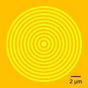
Fig. 1. Schematic illustration of the simulated bull's eye structure.
Download figure:
Standard image High-resolution imageIn this study, we propose combining a gate-defined QD with a bull's eye structure to increase the coupling between photons and electron spins in the QD. We design bull's eye structures on gate-defined QDs with QPC charge sensors, and simulate the electromagnetic field using the finite-difference time-domain (FDTD) method. We also examine the maintenance of the incident light polarization through a bull's eye structure.
2. Methods
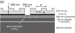
We performed simulations on optical transmission properties for the hybrid structures of QDs formed in a GaAs/AlGaAs QW with bull's eye structures using the FDTD method (Lumerical FDTD Solutions). The cross-sectional view of the simulated device structures is shown in Fig. 2. We studied two types of device structures, with bull's eye (Structure A), and without bull's eye (Structure B), as shown in Figs. 2(a) and 2(b), respectively. The diameter of the whole bull's eye was 15 µm. The incident light impinged normal to the plane and did not have a specific spatial beam profile. We employed a gate electrode pattern of a double QD similar to those used in previous works (see Fig. 3).11–13) The aperture at the center was located above the left QD. In the QW, a GaAs well layer was sandwiched by Al0.3Ga0.7As barrier layers. To design practical structures for the quantum state conversion from photons to electron spins, the well width of the QW was assumed to be 7 nm for an in-plane electron g-factor close to zero. This well width provided a target wavelength of 774 nm for light-hole excitation.12,24) The bull's eye structure was made of titanium and gold and was separated from the surface metal gates for the QD by a calixarene dielectric. In the following simulations, the diameter of the aperture was fixed at 360 nm, which is close to the value used in previous works.10–13)
Download figure:
Standard image High-resolution image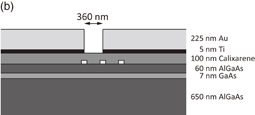
Fig. 2. Cross-sectional view of the device used for simulations. (a) Structure A with bull's eye structure. (b) Structure B without bull's eye structure. Both devices have QD gate electrodes.
Download figure:
Standard image High-resolution image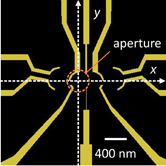
Fig. 3. Top view of the gate electrode pattern for a double QD with charge detectors. The dashed circle represents the position of the aperture.
Download figure:
Standard image High-resolution imageThe relation between the wave number of incident light, k, and that of a surface plasmon, kSPP, is described as25)

where θ is the incident angle of light, |G| = 2π/p is the reciprocal of the period of the grooves in the bull's eye structure, p is the period of the grooves, and m is an integer. Then, kSPP is given by
where λ is the wavelength of incident light, and εAu and εAir are the dielectric constants of gold and air, respectively. For the first-order diffraction (m = 1) at λ = 774 nm, we obtain p = 756 nm. If we use this period, the resonant wavelength becomes longer than 774 nm because of the Fano-type interaction.26–28) Therefore, we set p to be slightly smaller than 756 nm in order to obtain the resonant wavelength of 774 nm. In practice, various parameters of the bull's eye structure — the diameter of the aperture, the groove period, the depth of the grooves, and the ratio of the groove width to the groove period, among others — affect the transmission properties and allow us to design a device structure with optimal resonant wavelength and transmission.29,30) In the simulations, for simplicity, we fixed the depth of the grooves to 100 nm and changed the groove period p and the ratio of the groove width to the period.
3. Results and discussion
Figure 4 shows the simulated transmittance spectra at the QW layer for different periods p of the groove. Here, we define the transmittance as the ratio of the spatial integral of the Poynting vector over the device area for the transmitted light to incident light power. The transmittance of Structure A with a bull's eye structure is considerably enhanced by approximately 45–57 times at each resonant wavelength, compared with Structure B without the bull's eye structure. The resonant wavelength can be shifted by changing the period of the grooves. As the period p increases, the maximal transmittance gradually increases and the resonant wavelength becomes longer. In the discussion below, we select the period p at 710 nm because this period gives a resonant wavelength of 772 nm, which is close to the target wavelength of 774 nm for light-hole excitation. Although a change in the period p gives a simple way to set the resonant wavelength to the light-hole excitation in a g-factor-engineered QW, it is necessary to change another parameter simultaneously to achieve optimal transmittance at a resonant wavelength.
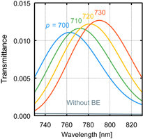
Fig. 4. Wavelength dependence of transmission of devices with bull's eye for various periods and without bull's eye.
Download figure:
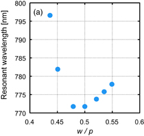
Standard image High-resolution imageFigures 5(a) and 5(b) show the simulation results of the resonant wavelength and transmittance at λ = 774 nm, respectively, for different groove widths w with p = 710 nm. As the ratio w/p deviates from 0.5, where the groove width is equal to the ring width, the resonant wavelength shows a red shift, and the transmittance at λ = 774 nm becomes maximum at w/p = 0.54. These results indicate that the groove width also affects the transmission properties.29,30) In other words, changing both w/p and p enables us to tune the transmittance at a desired wavelength for an arbitrary QW structure. In the following calculations, we use w/p = 0.54 since this value gives the highest transmission at λ = 774 nm, although this wavelength is not an exact resonant wavelength. Note that for further optimization of the transmittance at a resonant wavelength, we have to precisely change more other parameters.
Download figure:
Standard image High-resolution image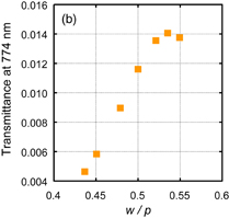
Fig. 5. Resonant wavelength and transmittance at λ = 774 nm as a function of w/p. p is 710 nm.
Download figure:
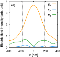
Standard image High-resolution imageNext, we discuss the influence of the device structure on the maintenance of incident light polarization. We evaluate the polarization of light at the position of a QD for λ = 774 nm. In this simulation, the electric field of the incident light is polarized along the x-axis. Figure 6(a) shows the electric field intensities Ex, Ey, and Ez along the x-, y-, and z-axis, respectively, of the transmitted light at y = 0 as a function of position x for the bull's eye structure with QD gate electrodes. x = 0 corresponds to the center of the aperture as well as that of the left QD. Ey and Ez are small near the center of the aperture, indicating that the linear polarization is almost completely maintained upon transmission. Away from the center of the aperture, Ey and Ez increase, and the linear polarization of the transmitted light is not well maintained. The asymmetric distributions of Ex, Ey, and Ez with respect to x = 0 are attributed to the presence of gate electrodes used to define the QD. The origin of the Ey and Ez components will be discussed below. To quantitatively discuss the polarization degradation, here, we define the polarization value as Ex/E, where E is the total electric field,  . Figure 6(b) shows the polarization value evaluated from Fig. 6(a) as a function of x at y = 0. Around the center of the aperture, the polarization value is almost unity and the linear polarization of the incident light is maintained. The polarization value slightly decreases away from the center because of the finite Ey and Ez components, but remains as high as more than 0.92 even at the edge of the aperture (x = ±180 nm). Maintaining the polarization outside the aperture may not be crucial since the light scattered to the outside may not contribute to the single photoelectron generation in the QDs.
Download figure:
Standard image High-resolution image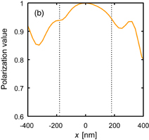
Fig. 6. (a) Distribution of electric field near QD with bull's eye structure at y = 0. (b) Distribution of polarization value Ex/E as a function of x at y = 0. The dotted lines indicate the positions of the aperture edges.
Download figure:
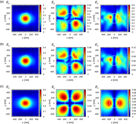
Standard image High-resolution imageFigures 7(a) and 7(b) show the spatial distributions of the electric field intensities Ex, Ey, and Ez for Structures A and B, respectively. Since the Ey and Ez components appear in both devices independently of the presence of the bull's eye structure [see Fig. 7(b)], the origins of Ey and Ez may be mainly attributed not to the bull's eye structure but to the circular aperture. The Ey and Ez components might be related to the surface plasmon at the edge of the aperture31) or to the effect of the focused evanescent field.32–34) Figure 7(c) shows the electric field intensity for a device similar to Structure B but without QD gates. The middle and right panels of Fig. 7(c) clearly show that the emergence of the Ey and Ez components is induced by the aperture. The electric field intensities Ey and Ez show clear fourfold and twofold symmetries in the x–y plane, as shown in the middle and right panels of Fig. 7(c), respectively. These symmetric distributions are strongly distorted by the presence of the QD gate electrode patterns, as shown in Figs. 7(a) and 7(b). By comparing Figs. 7(a) and 7(b), it can be seen that the overall spatial distributions of Ex, Ey, and Ez are not changed qualitatively by adding the bull's eye structure to the metal mask. We found that the bull's eye structure enhances the electric field intensities Ex, Ey, and Ez by a factor of more than 7 compared with the device without the bull's eye structure. This is quantitatively consistent with the enhancement of the transmission shown in Fig. 4. We conclude that the bull's eye structures significantly enhance the electric field and that the polarization is almost maintained.
Fig. 7. Spatial distributions of the electric field intensities Ex, Ey, and Ez of the transmitted light with bull's eye structure and QD gate electrodes (a), without bull's eye structure and with QD gate electrodes (b), and without bull's eye structure or QD gate electrodes (c). The left, middle, and right panels in each figure indicate the Ex, Ey, and Ez components, respectively. The dashed circles depict the position of the aperture. (Color bar unit: arb. unit)
Download figure:
Standard image High-resolution image
From the spectral width of the calculated transmission peak (Fig. 4), we evaluated the coherence time of the surface plasmon to be ∼11 fs, which is comparable to the coherence time of ∼18 fs deduced for a hole array structure used in an experiment of entangled photon transmission.21) Furthermore, the dissipation and decoherence of the surface plasmon in the bull's eye structures have to be examined. In the case of hole arrays, radiative decay has been discussed as being a possible source of the decoherence in a transmission of entangled photons.21) Ohmic loss is also considered in the hole arrays as an origin of decoherence and loss.22) Both radiative decay and ohmic loss are included in our simulations. Note that the conservation of quantum entanglement in a transmission has not yet been reported in the bull's eye structures.
4. Conclusions
We proposed combining a gate-defined QD with a bull's eye structure to largely enhance the transmission to the QD, and designed devices comprising a bull's eye structure on a gate-defined double QD formed in a GaAs QW with a well width of 7 nm. We found that, by choosing the appropriate groove period and groove width, the resonant wavelength can be tuned to a desired wavelength, which allows a coherent conversion, and that the transmittance can be enhanced more than 50 times compared with that without the bull's eye structure. In addition, we discussed the polarization preservation through the bull's eye structure. The polarization is well maintained around the center of an aperture in the metal mask and is slightly degraded away from the center. We found that the degradation of the polarization upon transmission is mainly attributed not to the bull's eye structure but to the aperture in the metal mask. Although the polarization degradation may be regarded as the loss of photons during photon-spin coherent conversion, the influence of the longitudinal wave component on the conversion process should be considered carefully because the Poincaré sphere picture is valid only for transverse waves.6,7)
Acknowledgments
This work was supported by Grants-in-Aid for Scientific Research A (No. 25246005) and S (No. 26220710), and for Young Scientists B (No. 15K17681), Innovative Areas "Nano Spin Conversion Science" (No. 26103004), CREST JST, and Dynamic Alliance for Open Innovation Bridging Human, Environment and Materials from MEXT.