
Abstract
We report a high-energy, high-repetition CW pumped Nd:YVO4 amplifier system, that produces 10.5 W, 14.2 ps pulses at 1064 nm wavelength and 5 W pulses at 532 nm wavelength with a repetition rate of 10 kHz. Pulses from a passively mode-locked Nd:YVO4 oscillator are first generated by cavity dumping, and then further amplified in a regenerative amplifier from 545 nJ to 1 mJ with a CW diode-pumped Nd:YVO4. After frequency doubling, 0.5 mJ pulses are obtained with a wavelength of 532 nm.
Export citation and abstract BibTeX RIS
High-energy, high-repetition-rate picosecond pulses are applicable to the domain of micro-machining.1) A regenerative amplifier2–4) (RA) is an important part of most picosecond and femtosecond solid state laser systems. Regenerative amplifiers functioning at high repetition rates can have period doubling bifurcations that lead to a chaotic distribution of energy.5–8)
In this study, the intracavity energy is instantaneously dumped from a standard picosecond oscillator instead of a power amplifier. Then, the dumped pulses are innovatively amplified by a regenerative amplifier. At the same time, the output pulses without self-excitation oscillations are generated from the high-energy seeds. This paper provides a new way to generate steady pulses using a regenerative amplifier without self-oscillation. The steady pulses are generated by the cavity-dumped and regenerative amplifier system (CDRA).
In 2004, a 5.3 W average output power with a pulse repetition-rate of 40 kHz was achieved using a Nd:YVO4 regenerative amplifier by Siebold et al.10) In 2005, a 10.8 W average output power with a pulse repetition rate of 20 kHz and a pulse duration of 10.2 ps was achieved using a Nd:YVO4 regenerative amplifier by Kleinbauer et al.11) In 2009, a 33.7 W output power with a pulse repetition rate of 20 kHz and an adjustable pulse duration between 217 ps and 1 ns was achieved using an 888 nm diode-pumped Nd:YVO4 regenerative amplifier by Lührmann et al.3) In 2013, an average power output of 4.7 W was obtained, with a repetition rate between 1 and 10 kHz, and a 15 ps pulse width by Zhang et al.12) In this paper, we report our results on a CW diode-pumped, Nd:YVO4 regenerative amplifier based on the CDRA system that delivers 1 mJ, 14.2 ps pulses with a wavelength of 1064 nm and repetition rate of 10 kHz. Thus far, 10.5 W is the highest power generated in a rod Nd:YVO4 regenerative amplifier with a pulse duration of 14.2 ps at 10 kHz.
The RA operation cycle consists of two successive stages called the pump phase and the amplification phase.9) The population inversion grows up in the pump phase and consumes a certain portion of the stored energy while the seed amplification takes place during several round trips in the amplification phase. High-repetition-rates of 10 kHz or higher, can reduce the energy loss due to spontaneous emission and improve the optical conversion efficiency.
The experimental setup is shown in Fig. 1. First, pulses are generated in a Nd:YVO4 oscillator that provides 2.9 nJ, 10 ps pulses, with a repetition rate of 74.3 MHz, a wavelength of 1064 nm, and are end pumped with an 11.5 W, 808 nm CW diode laser.
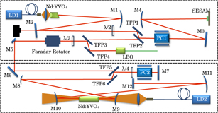
Fig. 1. Experimental setup. PC: pockels cell, TFP: thin film polarizers.
Download figure:
Standard image High-resolution imageNd:YVO4 was chosen as the gain medium because it has sufficient gain bandwidth to directly generate pulses with widths around 10 ps and a high emission cross section (15.6 × 10⁻¹⁹ cm2 9)). The crystal (a-cut) is 0.5 at. % doped and has a size of 3 × 3 × 5 mm3 with a 5° angle on one side to avoid the etalon effect. The Nd:YVO4 has a high reflection coating at 1064 nm wavelength and a high transmission coating at 808 nm wavelength on the side that is pumped.
A summary of the cavity mirrors (Table I) is as follows. The semiconductor saturable absorber mirror (SESAM) is a passive mode-locking device that is placed at one end of the cavity as an end mirror mounted on brass heat sink with an absorption coefficient of 2% and a saturation fluence Fsat of 50 µJ/cm2. The response time of the SESAM is about 10 ps. Thin film polarizers (TFP) are used in pairs to improve the intracavity contrast ratio.
Table I. Summary of cavity mirrors. The experimental setup is shown in Fig. 1.
| Mirror | Details |
|---|---|
| M1 | Concave mirror: 600 mm radius of curvature (ROC), reflection (R) ≥ 99.90% at 1064 nm, transmission (T) ≥ 99.90% at 808 nm |
| M2 | Coupled output mirror: flat mirror, T = 1.2% at 1064 nm |
| M3, M7, M12 | Flat mirror: R ≥ 99.90% at 1064 nm |
| M4 | Concave mirror: 400 mm ROC, R ≥ 99.90% at 1064 nm |
| M5, M6 | 45° mirror: flat mirror, R ≥ 99.90% at 1064 nm |
| M8, M11 | Concave mirror: 2000 mm ROC, R ≥ 99.90% at 1064 nm |
| M9, M10 | Convex mirror: −1000 mm ROC, R ≥ 99.90% at 1064 nm, T ≥ 99.90% at 880–914 nm |
β-BaB2O4 (BBO) is used for the pockels cells. The value of the quarter wavelength voltage depends on the laser wavelength (λ = 1064 nm), the distance between the electrodes (d = 4 mm), the refractive index of the crystal (no = 1.655), the effective electro-optic coefficient (d22 = 2.2 pm/V) and the crystal length (L = 20 mm). Equation (1) gives the value for the quarter wavelength voltage:

By calculation, the value of the λ/4 voltage is 5300 V.
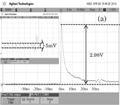
The cavity dump has and output power of 15 mW and a repetition rate of 10 kHz. The output waveform is shown in Fig. 2(a). In order to obtain better passively mode-locked pulse signals from the cavity dumping process, which triggers the high voltage (HV) power supply, the dumping rate is set to 71.7% using the 3800 V HV. The cavity oscillation is monitored by a fast photodetector and a dumping rate of 71.7% is shown in Fig. 2(b). Although a perfect waveform is obtained, the background continuous mode-locked pulse is still present [Fig. 2(a) inset] because the extinction ratio of the thin film polarizer is not good enough. The amplitude of background continuous mode-locked pulse is 5 mV, and the voltage of the cavity dumped pulse is 2.98 V. The ratio between the cavity dumped pulse and background continuous mode-locked pulse is 600.
Download figure:
Standard image High-resolution image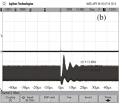
Fig. 2. (a) Single dumped pulse. (The abscissa has units of time and the scale is 10 ns/grid.) Shown in the inset are the background pulses. (The abscissa has units of time with a scale of 20 ns/grid.) (b) The process of Q-switched mode locking after one dumping. (The abscissa has units of time and the scale is 10 µs/grid.)
Download figure:
Standard image High-resolution imageWe measured the power and the energy of the cavity dumped pulse at 10 kHz and obtained 15 mW and 0.545 µJ, respectively.
The relationship between power and energy is as follows:

Here, P is power, E is energy, and ν is the repetition of the cavity dumped pulse. The calculated energy is 1.5 µJ in agreement with the power of 15 mW. The difference between the calculated values and the measured values is caused by the background pulses. The output power from the TFP2 is 5 mW when the high voltage power supplied to the BBO is turned off. Once the background power from the continuous mode-locked pulses was subtracted, the experimental and calculated values are consistent.
In the second step, the cavity dumped pulses are amplified by the regeneration cavity and 10.5 W, 14.2 ps pulses at 10 kHz are obtained at the fundamental frequency. An autocorrelation trace of the CDRA pulses is shown in Fig. 3. The beam quality and beam intensity profile is shown in Fig. 4 and the M2 is 1.3.
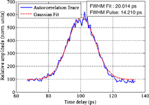
Fig. 3. Measured autocorrelation trace and Gaussian fit for the amplified pulse.
Download figure:
Standard image High-resolution image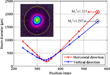
Fig. 4. Beam intensity profile and beam quality for the CDRA system at 10 kHz. (The inset shows the beam intensity profile.)
Download figure:
Standard image High-resolution imageThe gain medium is a-cut, 0.5 at. % doped Nd:YVO4 with a size of 4 × 4 × 30 mm3. Nd:YVO4 has a high transmission coating at 1064 nm wavelength and coatings from 880 to 914 nm wavelength on both sides. The pump sources (LD2) are NLight fiber-coupled diode lasers (P4-100-0885-3-A-R01-S0030). The crystal has an effective absorption coefficient is 0.046 mm−1 at a wavelength of 886 nm. The continuous output power of the regenerative cavity is 23.92 W when the absorbed power is 60.85 W. The optical conversion efficiency is as great as 39.31%.
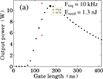
According to our theoretical analysis, the regenerative energy of the pulses is stable at 10 kHz while the energy of the seeds is between 1 nJ and 1 µJ.5–8) The parameters used for a simulation of Nd:YVO4 RA are shown in Table II. The high voltage duration (referred to as "gate length") is an important parameter that determines the number of round trips of the seeds in the regeneration cavity. The output power and stability of the Nd:YVO4 regenerative amplifier versus gate length is shown in Fig. 5. Double periodic phenomenon are generated at 133 ns (gate length), when the seed energy is 1.3 nJ. This phenomenon occurs more frequently at repetition rates 100 kHz or larger.8) However, the output energy is stable when the output power reaches its maximum. The output power as a function of gate length shows obvious differences between 1.3 nJ seeds and 545 nJ seeds. The peak output power for 545 nJ seeds occurs for a gate length of 119.7 ns. This is shorter than peak for 1.3 nJ seeds that occurs at a gate length of 172.9 ns. A 2.21 W self-excitation oscillation is generated at a gate length of 172.9 ns without any input seeds due to the high gain. By contrast, there are no self-excitation oscillation outputs for a gate length of 119.7 ns.
Download figure:
Standard image High-resolution image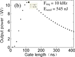
Fig. 5. The output power and the stability of the Nd:YVO4 regenerative amplifier as a function of gate length. The black dots indicates stable output, and the red dots indicates unstable output. (a) Eseed = 1.3 nJ and (b) Eseed = 545 nJ.5–7)
Download figure:
Standard image High-resolution imageTable II. Parameters used for the simulation of Nd:YVO4 RA.
| Small signal gain coefficient g0 | 2 |
| Cavity dumping frequency Freq (kHz) | 10 |
| Upper state lifetime τL (µs) | 100 |
| Seed energy Eseed (nJ) | 1.3 or 545 |
| Saturation energy Esat (nJ) | 1000000 |
| Losses per round trip L | 0.05 |
| Round trip time tR (ns) | 13.3 |
| Emission cross section9) σL (cm2) | 15.6 × 10⁻¹⁹ |
The best way to eliminate the period doubling bifurcations in a RA system is to improve the energy of the seeds. Seeds with a high energy are generated in a power amplifier or through cavity dumping. However, a pulse selector needs to be introduced to prevent extra pulses from consuming upper level population inversion, thereby reducing the gain in the power amplifier. In this paper, a 545 nJ seed is obtained only by cavity dumping without a high power pump source. A power of 40 W is difficult to obtain in a mode-locked oscillator with equal energy (545 nJ). The combination of cavity dumping and a regenerative amplifier is an innovative way to obtain stable pulses, and it is also compact and economical.
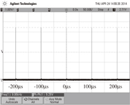
Signal synchronization is very important in the CDRA system. If the cavity dumping pulse is not selected by pockels cell 2 (Fig. 1), then the background continuous pulses (satellite pulses) will be amplified by the regenerative amplifier with an average output power of 6.5 W and a gate length of 119.7 ns. To synchronize the signals of the two PCs, the output pulse signal of the mode-locked oscillator is supplied to both PCs. The signal from PC1 triggers PC2. BBO and λ/4 are used as a Q-switch device for selecting and dumping the pulses. The pockels cell 2 is not only the Q-switch device for the regenerative cavity, but is also a pulse selector for the cavity dumped output pulses. The pulses are selected for amplification by measuring the distance of the two pockels cells and adjusting the pulse delay of two high voltage signals exactly. Cavity dumped output from the regenerative amplifier was achieved and the stable pulse train is shown in Fig. 6.
Fig. 6. Stable pulse train from the CDRA system. (The abscissa has units of time with a scale of 50 µs/grid.)
Download figure:
Standard image High-resolution image
Finally, pulses with a wavelength of 532 nm are generated by second-harmonic generation (SHG) in a 4 × 4 × 12 mm3 BBO crystal.
To conclude, this paper verifies the feasibility of pulse generation by CDRA. A CDRA system can provide stable pulsed output without self-excitation oscillations, especially in the frequency region where a RA will generate pulses with a chaotic energy distribution. To our knowledge, 10.5 W is the highest power generated in a rod Nd:YVO4 regenerative amplifier with a pulse duration of 14.2 ps at 10 kHz. Because of lower costs of CDRA, it will be used in industry.
Acknowledgment
The authors gratefully acknowledge financial support by the National Natural Science Foundation of China (61144007).