
Abstract
We developed an electrochemical (EC) sensor having dry reagents to detect pyrophosphoric acid (PPi) produced as a by-product of a polymerase-chain-reaction (PCR) amplicon for single nucleotide polymorphism (SNP) detection. The EC sensor is implementable in a lab-on-chip (LoC) system, and a sensor chip having side-wall electrical connections that enable electrical contacts from the top of the LoC has been developed. We also developed separated on-chip placement of dry reagents divided into three groups in a sensor cavity to suppress background current when there is no PPi. Using this chip, we successfully demonstrated SNP detection in the ABO gene from human blood samples, in combination with the allele-specific PCR amplification method using our developed LoC system.
Export citation and abstract BibTeX RIS
1. Introduction
A single nucleotide polymorphism (SNP) is a single base change from a consensus genome sequence. Some SNPs provide important information on the predisposition to certain diseases1) and affect the therapeutic response to certain drugs.2–5) Hence, detecting SNPs will be indispensable for personalized medication in diagnosis. However, today's SNP detection services at clinics and hospitals are not yet widespread. One of the main reasons would be that much lab work is required for sample preparation, including cell lysis, DNA amplification, and purification, as well as detection, which leads to difficulties in performing all of them at clinics and hospitals since the work is time-consuming and requires skilled personnel. Therefore, there is strong demand for automated SNP detection systems as a diagnostic tool.
It is considered that the lab-on-chip (LoC) approach, which has a great advantage for the integration of the components for sample preparation and detection owing to its miniaturized structure, is one of the promising methods, in particular, to realize such as an automated molecular diagnostic tool with ease of use, rapidity, and high sensitivity. However there are few reports on a fully integrated system for SNP detection by the LoC approach.6,7)
Recently, we proposed, for SNP detection a silicon-based integrated LoC system, with high-performance components: pumps, valves, mixer, polymerase-chain-reaction (PCR) reactor, filter, and electrochemical (EC) sensor in a small chip.8) Then, we improved the integrated design and demonstrated the chip operation using human blood, showing that automated SNP detection is possible within one hour with high sensitivity owing to allele-specific (AS) amplification and EC detection.9) In the development, we also miniaturized the EC sensor chip to accommodate the small sample volume (<1 µL) processed in LoC and demonstrated SNP sensing using liquid reagents.10)
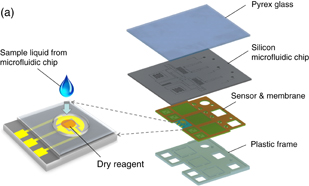
In an ideal operation, it is better that all the reagents for chip operation are preload and stored in the chip, preferably in the dried state, because doing so can eliminate the time needed to load the reagents, reduce the expertise needed to operate the device, reduce the risk of contamination, and enhance portability.11) In particular, dry-reagents implementation in a sensor chip has significance because the sensor chip could be used for multiple applications merely by replacing the reagents in accordance with the analytes. Figure 1(a) shows a schematic drawing of the concept of the LoC system having an EC sensor with a dry reagent. The system mainly consists of a plastic frame and a microfluidics chip. The plastic frame has a thin membrane made of silicone film, which contains components for flow control units, such as diaphragm pumps and valves, and also accommodates an EC sensor chip. The microfluidics chip has a silicon/pyrex stacked structure, which contains microfluidic components such as mixers, microreactors for PCR, and filters. An analyte processed in the microfluidic chip is transferred to the EC sensor chip, where it then dissolves and reacts with the dry reagents stored in the sensor cavity. After that, the analyte is ready for EC sensing.
Download figure:
Standard image High-resolution image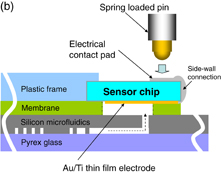
Fig. 1. (a) Conceptual schematic drawing of electrochemical sensor with a dry reagent implemented in a silicon-based-microfluidics LoC. (b) Cross-sectional drawing of the sensor chip connected to the LoC for SNP detection.
Download figure:
Standard image High-resolution imageFollowing the above concept, in this paper, we report on the development of an EC sensor that is implementable in a LoC system for SNP detection, that has dry reagents to detect pyrophosphoric acid (PPi) produced as a by-product of PCR amplification. We also report on the results of SNP detection in the ABO gene from human blood samples in combination with allele-specific PCR amplification using the LoC.
2. Operating principle, preparation and implementation of chip/reagents, and measurement procedure
2.1. Sensor chip fabrication and implementation to LoC for accommodation of dried reagents
Figure 1(b) shows a schematic drawing of the cross section for a LoC with an EC sensor chip for SNP sensing. The LoC is comprised of four layers: (1) Pyrex glass as the cover for microfluidics in the silicon layer, (2) silicon microfluidics capable of functioning of mixer, PCR, and filter, (3) sensor and membrane made of poly(dimethylsiloxane) (PDMS) that function as diaphragm-type pumps and valves, respectively, and (4) plastic frame made of poly(methyl methacrylate) (PMMA), which accommodates the sensor chip and pumps and valves. Details of the LoC structure and its fabrication process are described elsewhere.12)
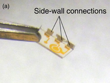
The sensor chip was dedicatedly fabricated on a glass substrate. The chip has three electrodes corresponding to the counter electrode (CE), working electrode (WE) and reference electrode (RE). The sensing electrodes were defined by a lift-off process; they were fabricated from a 100-nm-thick gold (Au) layer deposited on a 5-nm-thick titanium (Ti) adhesion layer. Part of the RE was covered with AgCl/Ag ink commercialized by ALS. The area of the working electrode is 0.29 mm2. After this process, the chips are diced to 5.5 × 3.6 mm2 with a dicing saw. Then, in order to obtain electrical contacts from the back of the sensor chip, side-wall connections composed of aluminum were deposited to the edge of the chip using a shadow mask by the metallization process. The fabricated sensor chip is shown in Fig. 2(a). After that, the sensor chip is placed face-down onto the membrane and secured with a thin adhesive layer. Thus, the sensor chip with dry reagents can be implemented in the LoC when the dried reagents are dotted on the surface of the EC sensor chip. A photograph of the sensor chip implemented in the LoC is shown in Fig. 2(b). The footprint of the LoC is 34 × 28 mm2.
Download figure:
Standard image High-resolution image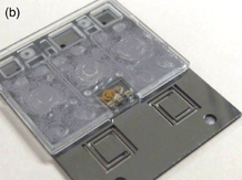
Fig. 2. (a) Fabricated sensor chip and (b) sensor chip implemented in LoC.
Download figure:
Standard image High-resolution image2.2. SNP detection principle with EC sensing of PPi
Prior to the EC detection of the SNP, an allele-specific PCR reaction is conducted. Owing to the use of allele specific primers (ASP), extension is only initiated when the SNP is present. At the same time, PPi is produced. The detection process in the EC sensor to sense the PPi is shown in Fig. 3. The words in orange represent components of reagents for PPi sensing. Through reactions with reagents (shown in Table I) involving three enzymes [pyrophosphatase, glyceraldehyde-3-phosphate dehydrogenase (GAPDH), and diaphorase], PPi provides electrons to potassium ferricyanide {K3[Fe(CN)6]} via glyceraldehyde-3-phosphate (GAP) and nicotinamide adenine dinucleotide (NAD+), a component of the detector chemical mixture, transforming it into potassium ferrocyanide {K4[Fe(CN)6]}. This ferrocyanide is then detected electrochemically; it is oxidized back to ferricyanide by applying oxidation voltage between the WE and RE, and then electrons are released as current flows in the sensor circuit. Details of ASP and EC sensing for SNP detection are also described in Refs. 10 and 13.
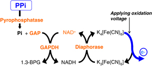
Fig. 3. Electrochemical reactions for PPi sensing. (The words in orange represent components of reagents for PPi sensing.)
Download figure:
Standard image High-resolution imageTable I. Components of reagent for PPi sensing.
| Components | Concentrationa) | Spotting volume for | |
|---|---|---|---|
| Test 1 | Test 2 | ||
| Tricine–NaOH (pH 8.8) | 45 mM | 1 µL | 0.34 µL (A) |
| NAD+ | 1 mM | ||
| MgCl2 | 1.7 mM | ||
| K3[Fe(CN)6] | 10 mM | ||
| GAP | 10 mM | 0.33 µL (B) | |
| Diaphorase | 10 U/mL | 0.33 µL (C) | |
| GAPDH | 32 U/mL | ||
| PPase | 5 U/mL | ||
a) Final concentration in mixture of spotting (total 1 µL).
2.3. Preparation of dry reagents
We prepared dried reagents under two different conditions named Test 1 and Test 2, as indicated in Table I. Reagents for Test 1 are mixtures of all the chemicals for EC sensing and are deposited as a drop with a volume of 1 µL. Reagents for Test 2 are mixtures of chemicals, group A [containing tricine–NaOH (pH 8.8), NAD+, and MgCl2], group B (containing GAP), and group C (containing enzymes), that are separately deposited dropwise with volumes of 0.33–0.34 µL. After that, the chips for Test 1 and Test 2 were loaded into a vacuum chamber for 15 min to dry the deposited chemicals. The chamber has a cold trap at a temperature of −50 °C, which is specialized for freeze-drying. The same procedure is also followed on the sensor chip for the demonstration of SNP detection in combination with LoC.
2.4. Measurement procedure
2.4.1. Measurement with PPi for characterization of EC sensor with dry reagents
In order to investigate the PPi response using the prepared EC sensor with dry reagents, we performed EC sensing experiments with dedicated EC sensor chips outside of the LoC. PPi detection was demonstrated at a concentration typical for SNP DNA replication. The potentiostat circuit was used in a chronoamperometric mode. Three different concentrations of PPi (final concentrations of 0, 0.05, and 0.1 µM) were prepared and dropped onto the dry reagents for Test 1 and Test 2, prepared by the procedure described in Sect. 2.3. Then, only 1 µL of the total mixture was transferred to the sensor chip by hand. After waiting 5 min, the potential of the WE was set at 0.6 V to generate oxidation potential and the time dependence of the current was measured.
2.4.2. Measurement for SNP detection processed in LoC
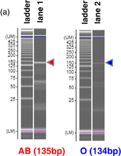
SNP detection was demonstrated by typing human genes in experiments conducted on AB- and O-type human blood, which, in the ABO gene, differ by only one nucleotide.12) Target sizes of fragments after PCRs are 135 bp for AB-type blood and 134 bp for O-type blood. In the LoC, 1 µL of diluted human blood (20%) and reagents for first (1st) and second (2nd) PCRs were preloaded and transferred to the mixer at flow rates of typically 0.25 and 2.25 µL/min, respectively. Then, cell lysis and DNA amplification were performed within 21 min in the 1st PCR. After the 1st PCR, the sample solution was purified using a pillar filter, and AS amplification was performed in the 2nd PCR. Details of the PCR conditions are described elsewhere.14) Then, 1 µL of the amplified product was transferred to the EC sensor chip with dry reagents divided into three groups (as Test 2). After waiting 5 min, current was measured by applying an oxidation voltage at 0.6 V in the chronoamperometric mode in a potentiostat circuit.
3. Results and discussion
3.1. PPi sensing using dry reagents prepared under different conditions
Figure 4 shows photographs of the state of dry reagents prepared under different conditions after freeze-drying and after dissolution in PPi solution. Dry reagents for Test 1 with a single spot [Fig. 4(a)] are not completely dissolved in PPi solution and some aggregates are observed in the mixture [Fig. 4(b)]. Using this mixture, sensing with different concentrations of PPi is conducted on the EC sensor chip. The result is shown in Fig. 5 by the blue dots and line. The measured current from the mixture in Test 1 is independent of PPi concentration, and high background current is observed even when there is no PPi. As the aggregates indicate, this result implies that an unfavorable chemical reaction might have occurred in the mixture. One possible reason for the high current under the condition of no PPi is that this aggregation itself might contribute the high current. Another possible reason might be the secondary reaction in the glyceraldehyde-3-phosphate dehydrogenase (GAPDH) reaction. A mechanism for GAPDH reactions has been mentioned in Ref. 15. The mechanism indicates that some NAD+ could gradually turn into NADH in the presence of GAP even when there is no PPi. Hence, NADH and ferrocyanide come out easily, which could generate high current under the condition of no PPi. This secondary reaction might occur easily during mixing and drying. In order to suppress the secondary reaction, we tried a separate placement of dry reagents divided into three groups: group (A) [tricine–NaOH (pH 8.8), NAD+, and MgCl2], group (B) (GAP), and group (C) (enzymes) as indicated for Test 2 in Table I. Dry reagents in Test 2 with three separate spots [(A), (B), and (C) in Fig. 4(c)] are completely dissolved in PPi solution, as shown in Fig. 4(d). Using these mixtures, sensing with different concentrations of PPi is conducted on the EC sensor chip. The result is shown in Fig. 5 by the red dots and line. The measured current from the mixture of Test 2 is dependent on the PPi concentration, and the background current clearly decreased under the condition of no PPi. These results suggested that separate spots are effective for highly sensitive PPi sensing with dry reagents.
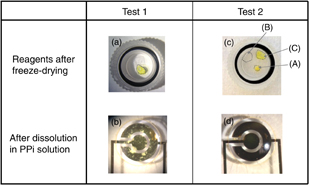
Fig. 4. Reagents (a) and (c) after freeze-drying, and (b) and (d) after dissolution in PPi solution for Test 1 and Test 2, respectively. The groups in (c) are group A [containing tricine–NaOH (pH 8.8), NAD+, and MgCl2], group B (containing GAP), and group C (containing enzymes), as indicated under Test 2 in Table I.
Download figure:
Standard image High-resolution image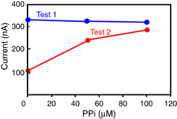
Fig. 5. Measured current signals depending on different concentrations of PPi for the samples of Test 1 and Test 2.
Download figure:
Standard image High-resolution image3.2. Demonstration of SNP detection in combination with LoC
Finally, we demonstrated SNP detection in the ABO gene from human blood samples combined with the allele-specific PCR amplification method through the developed LoC system. Following the conditions of Test 2, we separately dotted and dried the three mixtures of reagents on the sensor chip directly for the demonstration of SNP detection. The top view of the sensor chip is shown in Fig. 6. Figure 6(a) shows the schematic layout around the sensor chip. The sensor cavity is surrounded by a membrane, indicated in green. Part of the RE is covered with AgCl/Ag ink, and the microfluidics channel from the LoC is connected to the sensor cavity and approachs the area of the RE, because the RE region must always be wet to maintain stable current measurement. Photographs of sensor chip after separate dotting of liquid reagents and after freeze drying are shown in Figs. 6(b) and 6(c). As shown in Fig. 6(c), dry reagents were immobilized on the sensor electrodes. Then, the chip having dry reagents were set into the LoC. Figure 6(d) shows the system after filling the PCR amplicon. No aggregates are observed in direct dotting to the sensor chip. This indicates that the sensor chip with dry reagents is compatible with the LoC.
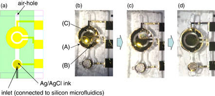
Fig. 6. (a) Schematic layout around sensor chip (sensor cavity is surrounded by membrane indicated by green color), and photographs of sensor chip (b) after separate dots of liquid reagents, (c) after freeze-drying, and (d) after filling the PCR amplicon containing PPi.
Download figure:
Standard image High-resolution imageThe selectivity of the 2nd PCR with respect to SNP was confirmed by gel electrophoresis, as indicated by lanes 1 and 2 in Fig. 7(a). The fragment from AB-type blood is strongly amplified (lane 1), while the fragment from O-type blood (lane 2) is little amplified. Figure 7(b) shows the time dependence of the average current with the amplicon from AB- and O-type blood samples. The current from the AB amplicon was always larger than that from the O amplicon. The efficiency of the SNP detector was demonstrated.
Download figure:
Standard image High-resolution image
Fig. 7. SNP detection result with the sensor having dry reagents for the samples of AS-PCR amplicons. (a) Gel electrophoresis patterns. (b) Current vs time for AB- and O-type blood and negative control after amplification using ASP.
Download figure:
Standard image High-resolution image
4. Conclusions
An EC sensor was implemented in a lab-on-chip (LoC) system, resulting in a sensor chip having side-wall electrodes that enable electrical contact from the top of the LoC. The functionality of an EC sensor with dry reagents was tested, and low background current was achieved in sensing using separate dots of different reagent mixtures. SNP detection in the ABO gene from blood was also successfully demonstrated with the dry reagents.
Acknowledgments
The authors would like to thank Dr. Peter Peumans and Liesbet Lagae at IMEC for their helpful support and encouragement throughout this work.