
Abstract
We report the realization of acoustic energy harvesting for low-frequency sound in a subwavelength system consisting of eight multiple-cavity units. This exotic energy harvesting phenomenon arises from a compound monopole Mie resonance (MMR) induced by mutual coupling between the system structure and the MMR of each unit. More importantly, the center intensity can reach about 9000 Pa2 with the parameter r/r0 of 0.73, providing the feasibility for realizing energy harvesting in a low-energy environment. The proposed system has rich compound Mie resonances, high energy harvesting, and strong robustness, which provides diverse routes to design novel acoustic devices with versatile applications.
Export citation and abstract BibTeX RIS
Nowadays renewable and clean energy have aroused more and more attentions owing to increasing environmental problems induced by traditional resources. Energy harvesting is defined as focusing and confining various ambient energy for use at a later time, including light,1) heat,2) wind,3) biochemical energy,4) and mechanical vibration,5) etc. With the rapid development of energy production and microelectronic devices,6) acoustic energy has attracted great interest from both physics and engineering communities owing to its clean, renewable, and abundant properties. However, owing to its relatively low power density in natural environments, acoustic energy generally needs to be focused or confined by special designed structures with a capability of acoustic energy harvesting (AEH).
Conventional Helmholtz7) and cavity resonators8,9) can be utilized to focus and confine acoustic energy and realize AEH simultaneously. References 8, 9 realized an AEH device based on a quarter-wavelength straight tube resonator, which could generate and confine standing acoustic energy inside the tube, and its working frequency is closely related to tube size. In the recent years, the emerging phononic crystals (PCs)10–13) and acoustic metamaterials (AMMs)14–19) with rich physics and many exotic properties has attracted great interest for designing AEH systems.20–23) Based on the Bragg scattering and local resonance mechanisms, acoustic band gaps of PCs can be adjusted and subsequently designed to realize AEH.24,25) Besides, by using the negative refraction mechanism, many acoustic energy focusing devices are realized by gradually changing structure parameters of PCs.26–28) However, the large lattice constant of PCs at low frequency hinder the applications of AEH owing to its structure size limitation. To overcome this, AEH devices with higher refractive index and thinner thickness are realized based on AMMs consisting of different units, such as Helmholtz resonator,29,30) cross structure,31) coiling up space,32,33) etc. Moreover, as a category of AMMs, acoustic metasurface34–36) has the advantages of ultrathin planar structure and wholly controlled phase delay, which shows great capabilities for designing advanced AEH devices with wavefront manipulation.37–39) Although the aforementioned systems have realized AEH through a variety of mechanisms, none are concerned with the design of subwavelength AEH structures at low frequency in low-energy environments.
Recently, a type of maze-like unit consisting of eight zigzag channels is proposed to realize rich Mie resonances, in which its monopole Mie resonance (MMR) mode can be used to realize high reflectance for low-frequency sound, and the size of the maze-like unit is only about 0.15λ.40) Moreover, the rich Mie resonances provide a variety of acoustic potential applications at low frequency, including the trapping,41) extraordinary transmission,42,43) enhanced emission,44) and directional propagation45) etc. Therefore, it inspires us to design an AEH system at low frequency in a low-energy environment based on Mie resonance units.
In this work, we propose a subwavelength AEH system for low-frequency airborne sound, which consists of eight multiple-cavity units with rich artificial Mie resonances. The AEH arises from the compound MMR of the system based on a type of out-phase resonance induced by the mutual coupling between the system structure and the MMR of the eight units. More importantly, we investigate the manipulation of the AEH performance by adjusting the inner radius r and the distance d of the units, in which the acoustic intensity can reach about 9000 Pa2 when the parameter r/r0 is selected as 0.73. Such a high intensity provides the feasibility for realizing AEH in a low-energy environment. Furthermore, the influences of incident acoustic directions and system shapes on AEH are also discussed in details, showing strong robustness of AEH.
As schematically shown in Fig. 1(a), we propose a circular multiple-cavity unit consisting of a central cavity surrounded by eight interconnected same resonant cavities, in which the cavities are filled with air and made of epoxy resins to satisfy the sound hard boundary condition. The thickness of solid frame is t, the width of channels is w, and the open width of cavities is h, and the outer and inner radii are R and r, respectively. Here, we adopt the finite element software (COMSOL Multiphysics) to numerically simulate acoustic characteristics of the multiple-cavity unit. The structure parameters are selected as t = 2.0 mm, h = 4.5 mm, w = 4.6 mm, r = 3.0 cm, and R = 5.0 cm, and the material parameters are used as follows: the density ρ = 1050 kg m−3, the Young's modulus E = 5.08 GPa, and the Poisson ratio v = 0.35 for epoxy resin; and ρ = 1.21 kg m−3 and the acoustic velocity c = 343 m s−1 for air.

Fig. 1. (Color online) (a) Schematic of a multiple-cavity unit. Simulated (b) pressure amplitude and (c) phase eigenfunctions of MMR of a multiple-cavity unit.
Download figure:
Standard image High-resolution imageFurther simulations about the eigenmodes show typical features of Mie resonances. The Mie resonances of the unit in Fig. 1(a) can be obtained by its multiple-cavity structure. Figures 1(b) and 1(c) show the pressure and phase eigenfunctions of MMR at 634 Hz. It is found from that, the MMR can concentrate acoustic energy in the multiple-cavity unit [Fig. 1(b)], and all cavities in the unit show a collective in-phase feature [Fig. 1(c)]. Besides, the diameter of the proposed multiple-cavity unit is only about 0.185λ, and the effective velocity the equivalent physical model of the unit is much slower than that of air (see the online supplementary data, available online at stacks.iop.org/APEX/12/044002/mmedia), which are similar to those of the previous maze-like structure.40)
To further demonstrate the MMR of the unit, we theoretically calculate the eigenfrequencies of the MMR by using the acoustic scattering theory (see the online supplementary data), in which the theoretical results agree well with the simulated ones. Moreover, the artificial Mie resonance dipole (1591 Hz) and quadrupole (1984 Hz) modes of the multiple-cavity unit are also simulated (see the online supplementary data). Note that the pressure and phase eigenfunctions cannot be distributed equally inside the unit for these modes, which is different from the characteristics of MMR. The rich Mie resonances of the multiple-cavity unit provide feasibility schemes to design acoustic devices with versatile applications.40–45)
As shown in Fig. 2(a), the MMR of the multiple-cavity unit can be excited by an external acoustic wave at 634 Hz, in which the initial amplitude of the incident wave is 1.0 Pa. Note that the acoustic energy is mainly concentrated in the unit induced by the MMR, and the intensity at the center of the unit is about 30 times than that of the incident wave. Figure 2(b) shows the acoustic intensities along the lines I and II in Fig. 2(a). It is found that the intensities along the lines I and II are larger than 26 Pa2, and reach about 32 Pa2 at the center of the unit, showing a high AEH performance. Moreover, the intensity spectrum at the center of the unit is shown in Fig. 2(c). The acoustic intensity is larger than 10 Pa2 in the range 590–680 Hz, and therefore the fractional bandwidth (the ratio of the bandwidth to the center frequency) could reach about 0.14.
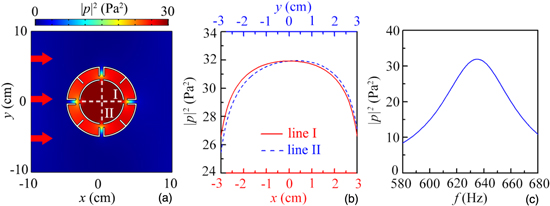
Fig. 2. (Color online) (a) Simulated distribution of pressure field induced by a multiple-cavity unit at 634 Hz, red arrows represent incident acoustic wave. (b) Acoustic intensities along lines I and II in a. (c) Acoustic intensity spectrum at center of multiple-cavity unit.
Download figure:
Standard image High-resolution imageBased on the multiple-cavity structure, we design an acoustic system consisting of eight multiple-cavity units, which enables the realization of compound Mie resonances. As shown in Fig. 3(a), the eight units with the same size are placed as a square shape, and the distance d between two adjacent units is 14.0 cm. Figures 3(b) and 3(c) show the simulated intensity and phase eigenfunctions of the compound MMR (716 Hz) of the system. As shown in Fig. 3(b), the compound MMR could also concentrate acoustic energy at the center region of the system, and the phase at the center region of the system is the same [Fig. 3(c)], showing a similar mode characteristic to the MMR [shown in Figs. 1(b) and 1(c)]. Meanwhile, the MMR also exists in the eight units, and the intensities in four units at the midpoints are higher than those at the corners owing to a small distance between the unit and the center position. Furthermore, the compound Mie resonance dipole (948 Hz) and quadrupole (1020 Hz) modes of the system are displayed (see the online supplementary data), in which the characteristics of both compound Mie resonances are similar to those of the corresponding Mie resonances.
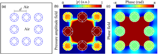
Fig. 3. (Color online) (a) Schematic of a square system composed of eight units. Simulated (b) pressure amplitude and (c) phase eigenfunctions of compound Mie resonant modes of system.
Download figure:
Standard image High-resolution imageSimilar to the MMR, the compound MMR of the system can also be obtained by an external acoustic wave at 716 Hz, which is shown in Fig. 4(a). The acoustic energy is concentrated at the center of the system, in which the intensity is about 60 times larger than that of the incident wave, and the system length is only about 0.79λ. Such a high intensity obtained at the center provides the feasibility for AEH in a low-energy environment. Compared with the AEH in a single multiple-cavity unit [Fig. 2(a)], the AEH at the center region of the system induced by the compound MMR is more convenient to be used in practice. Besides, the zoom of the intensity distribution of the system is displayed at the right side of Fig. 4(a). Note that, in addition to the incident direction of acoustic wave, all other acoustic velocity directions (white arrows) point toward the center of the system induced by the compound MMR, and thus the acoustic energy in the external area and the eight units is absorbed into the system structure, showing typical characteristics of energy harvesting. Therefore, based on the compound MMR, the system has the high performance of the AEH. Meanwhile, the AEH is further enhanced by the coupling of the MMR of the units. For comparison, we also simulate the compound MMR and its corresponding AEH in a system constructed by eight solid cylinders [shown in Fig. 4(b)], in which the system shape and the size of the solid cylinder are the same as those in Fig. 4(a). Note that the acoustic velocity direction is mainly consistent with the incident direction, and the characteristic of energy harvesting is not obvious. Therefore, the intensity at the center of the system is much smaller than that in Fig. 4(a). This is because the compound MMR of this system arises from the square structure but without the coupling the MMR of the eight units [zoom in Fig. 4(b)], which is different from the mechanism of Fig. 4(a).
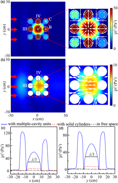
Fig. 4. (Color online) Simulated distributions of intensity field induced by two systems composed of (a) multiple-cavity units and (b) solid cylinders, respectively. Red arrows represent incident acoustic waves. Zooms at right side are intensity distributions of both systems, and white arrows represent sound velocity directions. Acoustic intensities along (c) line III and (d) line IV in a and b for three cases.
Download figure:
Standard image High-resolution imageFigures 4(c) and 4(d) show the acoustic intensities along the green dashed lines III and IV in Figs. 4(a) and 4(b), in which the corresponding results in the free space are also displayed for comparison. It is found that there exist three peaks along the lines III and IV for the multiple-cavity units, which further indicates that the AEH at the center region of the system is enhanced by the coupling of the MMR of the units. Besides, the maximum intensities in the units are larger than 120 and 80 Pa2 along the lines III and IV, respectively, while those for the solid cylinders and the free space are close to zero. This further indicates that the MMR does not exist in the solid cylinders and the AEH of this system is attributed to the square structure. Moreover, for the system composed of the multiple-cavity units, the intensity at the center can reach about 60 Pa2, and the full width at half maximum of AEH is only about λ/3 (16 cm) [shown in Figs. 4(c) and 4(d)]. Therefore, we can realize a subwavelength AEH in a low-energy environment based on the compound MMR of the system with the multiple-cavity units. Furthermore, we simulate the AEH induced by the compound MMR of the circle system (see the online supplementary data), in which the AEH performance in the circle system is much weaker than that of the square system.
Figure 5(a) shows the intensity spectra at points A, B and C [shown in Fig. 4(a)]. Note that the intensity peaks exist simultaneously for three points at f4 (716 Hz). Besides, at f1(542 Hz), f2(608 Hz), and f3(619 Hz), the intensity peaks also exist at points B and/or C, but it is very weak at point A. It is necessary to point out that the four frequencies are different from that of the MMR for a single multiple-cavity unit [634 Hz], while the MMR still exists in the eight units. Therefore, we deduce that the MMR at these frequencies arises from the mutual coupling of the units. However, the compound MMR of the system only exists at f4, which indicates that the coupling mechanism of the units at f4 is different from that at f1, f2, and f3. Furthermore, we also simulate the intensity distributions induced by the system at f1, f2, and f3 (see the online supplementary data). The results also demonstrate the aforementioned characteristics.
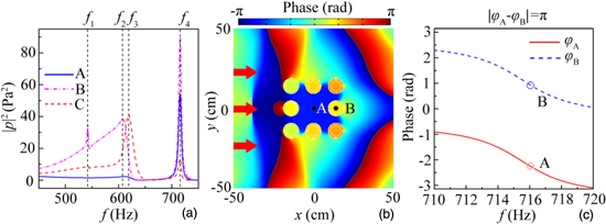
Fig. 5. (Color online) (a) Acoustic intensity spectra at points A, B, and C in Fig. 4(a). (b) Simulated distribution of phase field induced by system at 716 Hz (f4 in a). Red arrows represent incident acoustic waves. (c) Phase spectra at points A and B in b.
Download figure:
Standard image High-resolution imageTo further insight into the mechanism of the compound MMR, we simulate the phase distribution of the system induced by the system at 716 Hz, which is shown in Fig. 5(b). Similar to the phase distribution in Fig. 3(b), the phase distributions are almost the same in each unit, showing a typical characteristic of MMR. However, the phase at the center region of the system is almost opposite to those in the units. Figure 5(c) shows the simulated phase spectra at points A(φA) and B(φB) in Fig. 5(b) in the range 710–720 Hz. Note that the phase difference between points A and B (∣φA − φB∣) is calculated as π at 716 Hz, showing the out-phase characteristic between the center region of the system and the eight units. Therefore, we deduce that the compound MMR arises from a type of out-phase resonance induced by the mutual coupling between the system structure and the MMR of the eight units. To verify this, we also simulate the distributions of the phase field at f1, f2, and f3. The results show that the phase distributions are different in each unit, and the phase differences do not have the out-phase characteristic at f1, f2, and f3 (see the online supplementary data). Therefore, the compound MMR does not exist at these frequencies.
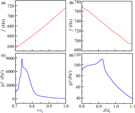
We also investigate the manipulations of the AEH performance by adjusting the inner radius r and the distance d of the system. Figures 6(a) and 6(b) show the eigenfrequencies of the compound MMR with different r/r0 and d/d0, where r0 and d0 are constants of 3.0 cm and 14.0 cm, respectively. Note that the eigenfrequencies of the compound MMR increase gradually with the increase of r/r0, but decrease gradually with the increase of d/d0, which indicates that the eigenfrequencies of the compound MMR can be manipulated by the parameters r and d. Moreover, we simulate the acoustic intensity at the center position with different r/r0 and d/d0, which is shown in Figs. 6(c) and 6(d), respectively. As shown in Figs. 6(c) and 6(d), the acoustic intensities (blue solid lines) at the center of the system vary with different r/r0 and d/d0, and can reach about 9000 Pa2 and 110 Pa2 when r/r0 = 0.73 and d/d0 = 0.93, respectively, which indicates that acoustic energy at the center can be manipulated by the parameters r and d. In addition, the high intensities at the center further demonstrate that the AEH induced by the compound MMR can be effectively applied to low-energy environments. Moreover, we simulate the intensity distributions induced by the system with different r/r0 and d/d0 (see the online supplementary data), which also clearly shows the manipulation of the AEH performance.
Fig. 6. (Color online) Eigenfrequencies of compound MMR with different (a) r/r0 and (b) d/d0. Acoustic intensities at center of system with different (c) r/r0 and (d) d/d0. r0 and d0 are constants of 3.0 cm and 14.0 cm, respectively.
Download figure:
Standard image High-resolution image
Furthermore, the AEH based on the compound MMR has strong robustness. The results show that the AEH with a high performance does exist with different incident angles, and can be obtained in different shaped systems (see the online supplementary data). Such a flexible AEH system with strong robustness can be applied to many specific application scenarios.
In conclusions, we have demonstrated a subwavelength AEH system at low frequency based on the compound MMR, in which the system is composed of eight multiple-cavity units with rich artificial Mie resonances. The results show that the AEH arises from the compound MMR of the system based on a type of out-phase resonance induced by the mutual coupling between the system structure and the MMR of the eight units. Besides, the AEH performances can be manipulated by the parameters r and d, and the acoustic intensity can reach about 9000 Pa2 when the parameter r/r0 is selected as 0.73. Such a high intensity provides the feasibility for realizing AEH in a low-energy environment. Moreover, the influences of the incident acoustic direction and the system shape on AEH are also discussed in details, showing strong robustness of AEH. The proposed subwavelength system exhibits rich compound Mie resonances, a high AEH performance, and a strong robustness that significantly extend our ability to control acoustic waves and have great potential applications in various scenarios, such as acoustic communication, acoustic sensing, energy collection, and ultrasonic medical treatment.
Acknowledgments
This work is supported by National Natural Science Foundation of China (Grant Nos. 11774137, 11834008 and 51779107), Six Talent Peaks Project in Jiangsu Province (Grant No. GDZB-019), Jiangsu Qing Lan Project, and the Practice Innovation Training Program Projects for Jiangsu University (Grant No. 201810299006Z).