


Abstract
We are developing the Gamma-Ray Astro-Imager with Nuclear Emulsion project, designed for 10 MeV–100 GeV cosmic γ-ray observations with a high angular resolution (5'/0 08 at 1–2 GeV) and a polarization-sensitive large-aperture (∼10 m2) emulsion telescope for repeated long-duration balloon flights. In 2018, a balloon-borne experiment was carried out in Australia with a 0.38 m2 sensitive area and a flight duration of 17.4 hr, including 6.7 hr of Vela observations. Significant improvements compared with the 2015 balloon-borne experiment were achieved by a factor of 5, including both an increase in effective area × time and a reduction in the background contribution. We aimed to demonstrate the telescope's overall performance based on detection and imaging of a known γ-ray source, the Vela pulsar. A robust detection of the Vela pulsar was achieved with a 68% containment radius of 042, at a significance of 6σ, at energies above 80 MeV. The resulting angular profile is consistent with that of a pointlike source. We achieved the current best imaging performance of the Vela pulsar using an emulsion γ-ray telescope with the highest angular resolution of any γ-ray telescope to date.
Export citation and abstract BibTeX RIS

Original content from this work may be used under the terms of the Creative Commons Attribution 4.0 licence. Any further distribution of this work must maintain attribution to the author(s) and the title of the work, journal citation and DOI.
1. Introduction
Observations of high-energy cosmic γ-rays provide direct information about high-energy phenomena in the Universe. The Fermi Large Area Telescope (LAT; ∼08 angular resolution at 1 GeV (68% containment radius);
6
Atwood et al. 2009, 2013) is among a number of telescopes that offer new insights by observing the γ-ray sky. However, both past and present observations have limitations. Improvements in angular resolution and polarization sensitivity are key to achieving the next breakthrough in the field of γ-ray astronomy.
There are several proposals for improvements, such as ASTROGAM (Angelis et al. 2018) and AMEGO (McEnery et al. 2019) with an active converter (passive converter-less) consisting of double-sided silicon detectors. Significant improvements below 1 GeV would be possible. However, there is still room for improvement in the performance of electron pair tracking with multiple Coulomb scattering. There are other approaches with a gaseous time projection chamber, such as HARPO (Bernard 2012, 2013; Bernard & Delbart 2012) and AdEPT (Hunter et al. 2014). Scattering material can be hugely reduced. On the other hand, it is difficult to increase the effective area.
We use a nuclear emulsion (emulsion film) that can record the three-dimensional trajectory of a charged particle with a spatial resolution of 50 nm. By precisely tracking the creation of an electron pair just below a γ-ray conversion point with an emulsion film (∼10−3 radiation length) and suppressed multiple Coulomb scattering, the incident γ-ray direction can be determined precisely, and it can be sensitive to any linear polarization of the γ-ray. Emulsion films can be made on a large scale. With the recent techniques of automatic large-area analysis and timestamping, a novel γ-ray telescope can be achieved.
We are developing the Gamma-Ray Astro-Imager with Nuclear Emulsion (GRAINE) project, pursuing 10 MeV–100 GeV cosmic γ-ray observations with a high (5'/008) angular resolution (68% containment radius) at 1–2 GeV and a polarization-sensitive large-aperture
7
(∼10 m2) emulsion telescope for repeated long-duration balloon flights (Takahashi & Aoki 2018). By means of scientific balloon-borne experiments, we can attempt to do the following: make pioneering polarization observations of high-energy γ-rays from pulsars, active galactic nuclei (AGNs), flares, and γ-ray bursts; directly probe proton acceleration through π0 detection and explore an emission mechanism with a spatial structure for supernova remnants; resolve the GeV γ-ray excess in the Galactic center region (Takahashi & Aoki 2018); probe new physics beyond the Planck scale through polarization observations of high-energy γ-rays propagating over cosmological distances; observe transient sources (e.g., γ-ray bursts and flares) with high sensitivity, high photon statistics, and high polarization sensitivity; make unique contributions to multimessenger astronomy, including joint measurements with neutrinos and gravitational waves; and contribute to improvements of a sensitivity gap in the MeV band from the high-energy region.
Various ground-based test experiments and developments of GRAINE have been undertaken (Takahashi et al. 2010; Takahashi 2011; Ozaki et al. 2016). In 2011, a first experiment with the balloon-borne emulsion γ-ray telescope was carried out at Taiki, Hokkaido, Japan, with a telescope of 125 cm2 sensitive area and a flight duration of 4.3 hr. In 2015, a balloon-borne experiment was performed in Australia with a 3780 cm2 sensitive area and a 14.4 hr flight duration. We thus demonstrated the feasibility and performance of experiments with the balloon-borne emulsion γ-ray telescope (Rokujo et al. 2013, 2018; Ozaki et al. 2015; Takahashi et al. 2015, 2016).
However, an important aim of the 2015 balloon-borne experiment was to detect γ-rays from the Vela pulsar, a known γ-ray source. That aim was not achieved because of problems with the telescope, i.e., malfunction of the mechanism to timestamp γ-ray events, improper timestamp operation that caused assignment of two timestamps to a single event, loss of operational time of star cameras, and loss of sensitive area due to damage to the emulsion film. During an improved balloon-borne experiment in 2018, we aimed to detect the Vela pulsar at energies above 100 MeV to demonstrate the telescope's overall performance.
In this paper, an overview of the emulsion γ-ray telescope is provided in Section 2. The instruments and the balloon-borne experiment carried out in 2018 are described in Section 3. Our procedure and details of the methodology applied to the flight data analysis are described in Section 4. The results of the flight data analysis are discussed in Section 5. The paper is summarized and an outlook is presented in Section 6.
2. Emulsion γ-Ray Telescope
The emulsion γ-ray telescope consists of a converter, a timestamper, and an attitude monitor (Figure 1).
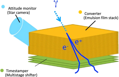
Figure 1. Schematic view of the emulsion γ-ray telescope.
Download figure:
Standard image High-resolution imageThe converter, which comprises a stack of emulsion films, detects, tracks, and measures energies of electron–positron pairs arising from γ-ray interaction. γ-ray events can be identified by requiring two track vertices without a parent track, topologically, and small-opening transverse momentum, kinematically. The momentum of each track is estimated from measurements of multiple Coulomb scattering. For some energy regions, dE/dx information is also available. Chance coincidences of charged particle tracks are the main background, occurring at a level below 5% thanks to the powerful anticoincidence with emulsion films located directly above the event (10−4–10−6 charged particle tracks), and excellent vertexing precision.
To reconstruct the direction of γ-ray arrival in celestial coordinates, the γ-ray direction in detector coordinates must be combined with the attitude information at the time of γ-ray arrival. As the emulsion film itself has no time information, multiple emulsion film stages (a multistage shifter) shifted at different cadences (like clock hands), called a timestamper, are used to create a time-dependent position relation during flight.
In principle, electron tracks can be reconstructed down to ∼10 MeV in the converter and timestamper, roughly corresponding to the lower limit for the γ-ray energy. In the emulsion γ-ray telescope, a lower limit to the energy range is determined based on the criteria for track reconstruction for a given track reconstruction efficiency and chance coincidence fraction. One demonstration has been given in Takahashi et al. (2015). The upper limit to the energy range is determined by photon statistics. The angular resolution depends on the γ-ray energy. The expected angular resolution is 1° at 100 MeV and 01 at 1 GeV. The effective area is determined mainly by the γ-ray conversion efficiency and the track reconstruction efficiency. The expected effective area is 2.1 m2 at 100 MeV and 2.8 m2 at 1 GeV for a 10 m2 sensitive area at normal incidence. The polarization sensitivity is limited by photon statistics. More information is given in Takahashi & Aoki (2018), and details of the intrinsic resolution of the emulsions and the scanning technique are given in Takahashi et al. (2015).
We aim to perform experiments with the balloon-borne emulsion γ-ray telescope during repeated balloon flights of one week (or longer) flight duration. Several groups have conducted balloon-borne emulsion chamber experiments with flight durations of one week or longer at mid-latitudes or in the Antarctic region, for 10 or more flights, producing data on cosmic-ray protons and nuclei (Asakimori et al. 1995, 1998; Apanasenko et al. 2001) as well as on very high-energy electrons and γ-rays (Nishimura et al. 1980; Kobayashi et al. 2012).
3. The 2018 Balloon-borne Experiment
An emulsion γ-ray telescope consists of a converter, a timestamper, and an attitude monitor. The detailed structure of the emulsion chamber is shown in Figure 2.

Figure 2. Detailed structure of the emulsion chamber. X0: radiation length; CFRP: carbon fiber reinforced plastic. (Units 3 and 4: alignment film, three emulsion films, 1.0 mm, 0.015 X0.) The Z-axis (polar axis) is oriented in the vertical direction; the X and Y axes point in the horizontal direction.
Download figure:
Standard image High-resolution image3.1. Converter
The converter, which consists of emulsion film stacks, detects γ-ray events. The emulsion film had a thickness of 330 μm and was composed of 75 μm thick emulsion layers with 45% volume occupancy of silver bromide crystals on both sides of a 180 μm thick polystyrene base. The converter consisted of 378 mm × 250 mm × 100 films × 4 units, for a total thickness of 33 mm or 0.51 radiation lengths, corresponding to a 33% conversion efficiency under normal incidence. Each converter unit was vacuum-packed. For the 2018 balloon-borne experiment, the fading of a latent image in the emulsion films was improved by reducing the volume occupancy of the silver bromide crystals (from 55 vol% to 45 vol%; Nishio et al. 2020). In addition, by increasing the thickness of the emulsion layer (from 70 to 75 μm), the γ-ray conversion efficiency was retained.
Alignment films are mechanically aligned emulsion films for the converter angle reference. The alignment films were placed on top of the converter. The alignment films consisted of the same type of emulsion films as used in the converter, which were vacuum-packed with a flat aluminum honeycomb board to maintain their flatness for calibration of the converter coordinates.
3.2. Timestamper
The timestamper, consisting of a multistage shifter, assigns timestamps to γ-ray events. By shifting positions between emulsion films in a predefined sequence, the recorded tracks have a time-dependent displacement between the emulsion films. From the track displacement, the recorded time can be reconstructed. To resolve longer time periods with higher time resolution, it is necessary to create many unique positional relations by many shifts in the single-stage shifter. Multiple emulsion films shifted at different cadences, called a multistage shifter, can create a great many unique positional relations among the emulsion films. The multistage shifter allows us to finely resolve the track time with an accuracy of better than one second for longer periods with smaller shifts. The multistage shifter, co-developed with Mitaka Kohki Co. Ltd., comprised three shifted stages and a static interface stage between the converter and the timestamper (see Figure 3). Gaps between the stages were 1 mm each, except for a 2 mm gap between the bottom stages. The emulsion film had a thickness of 280 μm and consisted of 50 μm thick emulsion layers on both sides of a polystyrene base. Thinner emulsion layers were implemented to reduce multiple Coulomb scattering events for track reconstruction while ensuring the track-finding efficiency. The emulsion films were 388 mm × 250 mm, which is longer than the converter in order to cover the whole converter even when the shifter is moved to its maximum end position. Two emulsion films were vacuum-packed with 600 μm thick carbon fiber reinforced plastic (CFRP) to avoid deflection by their own weight. The vacuum envelope was an aluminum-laminated plastic film of 118 μm thickness. 8 The packs (CFRP-backed emulsion films, vacuum-packed within the envelope) were embedded in 1 mm thick frame-shaped stages which consisted of the stage without a grid (only a frame), except for the third stage. A pack on the third stage contained three emulsion films with a 300 μm thick acrylic push-up bottom to reduce the gaps between the bottom stages. Nominal gaps between packs were 600 μm (corresponding to 840 μm separations between emulsion films between the stages) and 420 μm between the bottom stages (corresponding to a 660 μm separation between emulsion films). The total thickness of the sensitive area was 7 mm or 0.04 radiation lengths. Four units of the emulsion film packs (the rectangles in Figure 3) were deployed on the multistage shifter. In the 2015 balloon-borne experiment, half the sensitive area was inoperative for half the time due to unexpected increases in stage friction. For the 2018 balloon-borne experiment, the emulsion film mounting on the multistage shifter was redesigned to prevent the unexpected stage friction. Emulsion film packs with CFRP backing were embedded in the frame-shaped stage. This redesign ensured proper operation of the stage, reduced the distance between emulsion films between the stages for track reconstruction, and increased the effective area. Due to the reduction in the separation of the emulsion film between the stages, the track extrapolation distance between the stages can be reduced by a factor of 1.4 or more. Therefore, the allowed area for track reconstruction between the stages can be reduced by a factor of 2 or more. As a result, the signal-to-noise ratio for track reconstruction between the stages can be increased by a factor of 2 or more. For an increased effective area, the conventional grid-shaped stage has a 65% aperture ratio. The frame-shaped stage has a 100% aperture ratio. As a result, the effective area, particularly for low-energy γ-rays (e.g., 100 MeV), can be increased by ∼20%. In 2015, because of improper operational parameters of the timestamper, the position relations among the stages were not unique. Therefore, two timestamps were assigned to single events. This led to twice the background. The operating parameters were revised to ensure that the operation was based on a similar operation in an accelerator neutrino experiment, J-PARC T60, where the same multistage shifter hardware was employed as a timestamper (Yamada et al. 2017). The motion of the first stage is surcharged to the turnaround of the second stage to avoid the risk of overlap between the outward and return motions of the second stage as there is substantial uncertainty in the accuracy of the second stage at turnaround. The details of previous configuration of the multistage shifter are given in Takahashi et al. (2016).
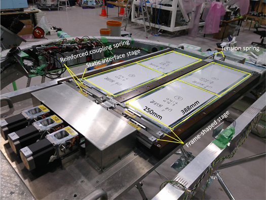
Figure 3. Photograph of the multistage shifter. Each rectangle represents one unit.
Download figure:
Standard image High-resolution imageEmulsion films for the converter and multistage shifter were produced, performance-tested, and preprocessed (initialized, dried, and vacuum-packed). During preprocessing for the 2018 balloon-borne experiment, quality control of the emulsion films was performed by monitoring the temperature and relative humidity at multiple points and by sampling the processed emulsion films. The converter handled a large number of emulsion films. High quality and performance were essential for all emulsion films in the multistage shifter.
3.3. Attitude Monitor
The payload is kept almost horizontal, pointing to the zenith, and the sources are observed while they pass within the field of view around the meridian. The attitude monitor, composed of star cameras, records the pointing attitudes of the telescope for all γ-ray event timestamps. The star cameras consist of a near-infrared-sensitive CCD camera (2/3 inch (8.8 × 6.6 mm2), 1920 × 1440 pixels, 2 × 2 binning), a middle telephoto lens (85 mm focal length; F1.4), a low-pass filter (50% at 690 nm, 90% at >730 nm), and an 860 mm long hood with baffles and a controller, including storage. The low-pass filter and the near-infrared-sensitive CCD camera aim to increase the signal-to-noise ratio by reducing the atmospheric scattered background light during daylight. This lens and camera configuration results in a field of view of 5.9 × 4.4 deg2 and a pixel size of (6.1 × 10⁻³ deg2). Three star cameras were mounted on the gondola, spaced in azimuth by 90°. To align the converter units, as well as the units and the star cameras, relative angles were measured on the ground by a 3D coordinate measurement instrument, FaroArm(R), with better than ∼01 precision. For the 2018 balloon-borne experiment, a robust hardware and software system was constructed for stable and highly reliable operations and to facilitate recovery from system failure. In addition, the position and mounting were redesigned to avoid light scattering around the hood's aperture, to facilitate good reproducibility, and to ensure a slip-tight structure of the hood and camera axes. Moreover, the frame rate was set at 10 Hz, with a sufficient precision for attitude determination, taking into account the rate of change of attitude (mainly azimuthal rotation of the gondola, ∼01 s−1).
3.4. Pressure Vessel Gondola
Each component was mounted on a pressure vessel gondola. The pressure vessel, characterized by a 300 hPa differential pressure at maximum, contained the vacuum packs and consisted of membranous shells and rings. The thickness of the shell was ∼0.1 g cm−2. More details of the pressure vessel are given in Rokujo et al. (2019).
3.5. Balloon-borne Experiment
The final assembly was completed at the Alice Springs balloon-launching station in 2018 March. We checked the operation of the onboard equipment (multistage shifter, star cameras, temperature meters, pressure meters, global positioning system, and battery) and assembled them on the pressure vessel gondola. Converter films were reordered to distinguish the tracks accumulated before mounting the films. After mounting the emulsion films and rehearsing for the launch, we were ready for flight operations by the end of 2018 March (see Figures 4 and 5). After waiting for appropriate wind conditions, and after two aborted launch attempts, the balloon was eventually launched on 2018 April 26 at 06:33 Australian Central Standard Time (ACST). It reached an altitude of 38 km at 2 hr after launch. Next, the balloon started a level flight, driven by a westerly wind. Telescope operations were terminated at 22:15 ACST, and the gondola was released at 23:17 ACST. The gondola landed by parachute about 900 km east of Alice Springs and 250 km southwest of Longreach at 23:54 ACST. Figures 6 and 7 show the flight path from the launch point to the landing point. Figures 8 and 9 show the altitude and residual atmospheric pressure, respectively. The total flight duration was 17.4 hr, with nearly 15 hr of level flight at 35–38 km altitude and 3–5 hPa residual atmospheric pressure. The Vela pulsar was observed continuously for more than 6 hr within 45° of the zenith.
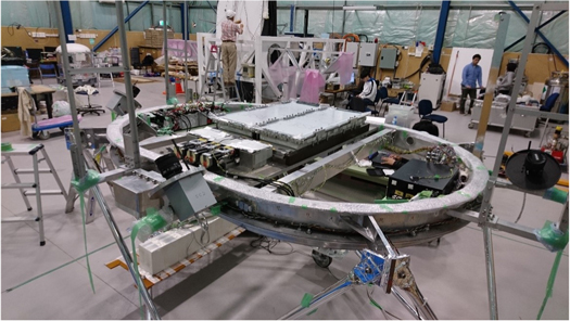
Figure 4. Photograph of the gondola during final preparation. The emulsion chamber on the multistage shifter was mounted inside a pressure vessel ring (1.5 m long along the minor axis). The star cameras, separated by 90° in azimuth, were mounted outside the pressure vessel.
Download figure:
Standard image High-resolution image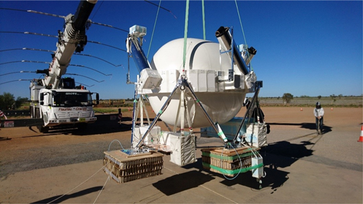
Figure 5. Photograph of the gondola, ready for flight. The vessel shell was closed and pressurized. The star cameras, equipped with a 860 mm long hood, are seen separated by 90° in azimuth.
Download figure:
Standard image High-resolution image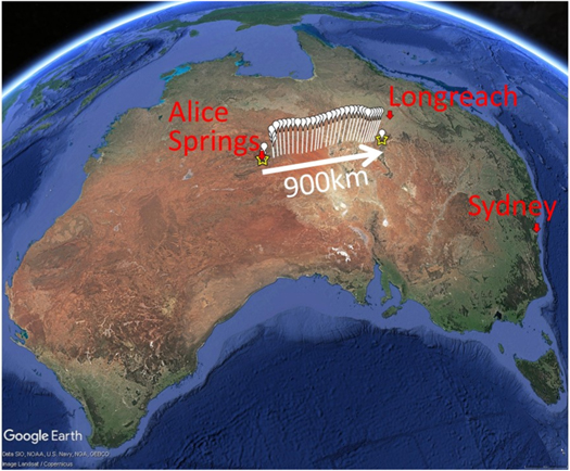
Figure 6. Google Earth image of Australia showing the flight path. The star symbols represent the launch (left) and landing (right) points.
Download figure:
Standard image High-resolution image
Figure 7. The flight path is shown from launch to termination in longitude (horizontal axis) and latitude (vertical axis). The circle and square represent the launch and landing points, respectively. The distance from Alice Springs to Longreach is 1060 km.
Download figure:
Standard image High-resolution image
Figure 8. Altitude of the gondola as a function of time.
Download figure:
Standard image High-resolution image
Figure 9. Residual atmospheric pressure as a function of time.
Download figure:
Standard image High-resolution imageFigure 10 demonstrates the operation of the multistage shifter. It operated after launch at a speed of 1 μm s−1 in the third stage. Starting from 14:48 ACST, the operation mode was changed to 10 μm s−1 in the third stage so as to cover the Vela pulsar within 45° from the zenith with sub-second timing resolution, sufficient to image the Vela pulsar with a resolution of 1° at energies above 100 MeV, which was our aim in this experiment. A 10 μm s−1 velocity in the third stage corresponds to a 0.5 s timing resolution in the precision of the 5 μm track connection. The operation was terminated at 22:15 ACST. Figure 10 also shows the repeatability with which the third and second stages of the multistage shifter returned to their reference positions. We stably operated the multistage shifter during the flight. The star cameras also operated stably during the flight (see Figure 11). Hence, the emulsion γ-ray telescope operated stably throughout.
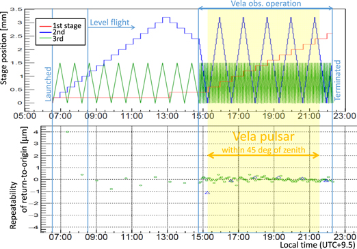
Figure 10. Operation (top) and stability (bottom) of the multistage shifter. The circles and triangles show the third and second stages, respectively.
Download figure:
Standard image High-resolution image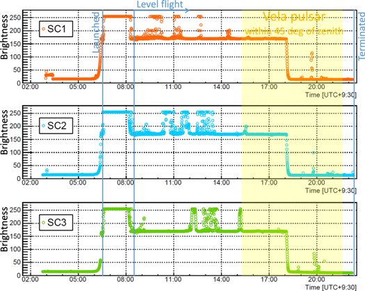
Figure 11. Operation of the star cameras. A brightness of 0–255 is defined as the average brightness of all pixels. The brightness saturation during the level flight indicates that the star camera's orientation was close to the Sun. The drop in brightness around 18:00 indicates sunset. The spikes after sunset indicate that the star camera's orientation was close to the Moon.
Download figure:
Standard image High-resolution imageThe gondola was successfully recovered from the landing point and transported to Longreach the next day. The emulsion films were sent by ground transportation from Longreach to Sydney on 2018 April 28 in a refrigerator at a temperature below ∼10°C. The placement of the timestamper film packs was controlled from pack retrieval to development. Post-flight emulsion film processing was done at the University of Sydney. All emulsion films were developed by 2018 May 13, with negligible loss caused by errors in emulsion development.
We thus successfully performed the 2018 balloon-borne experiment. Significant improvements were achieved with respect to the 2015 experiment. The stable operation of the multistage shifter yielded an increase in effective area × time. In 2018, the entire area was stably operated for the entire period. As a result, the effective area × time was increased by a factor of 1.3. The modified operation of the multistage shifter yielded a reduction in background. Thanks to our revision of operation parameters in 2018, the background was reduced to one-half of the 2015 background. The stable operation of the star cameras yielded an effective increase in observation time. The operational time of the star cameras in 2015 corresponded to a fraction of 0.56 of the total observation time because of the system instability and failure. Because of the stable operation in 2018, the effective observation time was increased by a factor of 1.8. The higher quality of the emulsion films increased the effective area. In 2015, 29 emulsion films (5.7% of the total) were damaged due to inadequate drying during preprocessing. The damaged emulsion films were concentrated on the bottom of the converter unit, which was the interface to the timestamper. Therefore, the converter unit could not be analyzed (one-quarter of the total area). By virtue of various tests and high-quality control in 2018, a higher quality of the emulsion films was achieved. Thus, the effective area of the films was increased by a factor of 1.3. Table 1 includes a summary of the improvements implemented. After taking into account the correlations between the improvement factors, a total improvement by a factor of  was achieved for the detection sensitivity to a γ-ray source with
  , where s and b are the numbers of signal and background events, respectively. (For more details of the detection sensitivity, see Takahashi et al. 2016.)
Table 1. Improvements in Sensitivity
| Effect | Factor | |
|---|---|---|
| Stable operation of multistage shifter | Area × time | 1.3 |
| Modified operation of multistage shifter | Background | 2 |
| Stable operation of star cameras | Time | 1.8 |
| High quality of emulsion films | Area | 1.3 |
| Total improvement in sensitivity (including correlations between improvement factors) | 5 | |
Download table as: ASCIITypeset image
4. Flight Data Analysis
4.1. γ-Ray Event Detection, Track Timestamping, and Attitude Determination
All emulsion films were scanned using the latest emulsion scanning system, the hyper-track selector (HTS; Yoshimoto et al. 2017).
For the converter, γ-ray event detections were processed for energies above 80 MeV. The converter outputs γ-ray events with local angles and energies. γ-ray events can be detected by requiring two track vertices without a parent track in topological and small-opening transverse momentum kinematics. An opening angle within 0.15 radians was applied in this analysis. This is sufficient to select electron pairs with γ-ray energies above 80 MeV. The γ-ray energy can be reconstructed from the momentum of an electron and a positron by measuring multiple Coulomb scattering events. The first and systematic momentum measurements with NETSCAN have been described elsewhere (Kodama et al. 2002, 2007; Nonaka 2002). γ-rays from hadronic interactions in the converter and those originating from the launch plate were confirmed. A more detailed analysis of the converter is provided by Nakamura et al. (2021).
For the timestamper, track timestamps were processed. Major improvements with respect to the 2015 experiment and proper operation of all stages were confirmed. Sub-second timing resolution, which was sufficient for the 1° imaging resolution above 100 MeV sought in this experiment, was evaluated using hadronic interaction tracks.
For the attitude monitor, the attitude determination was processed. Complementary attitude monitoring was performed by the three star cameras separated by 90° in azimuth. Attitude determination to within 98.9% of the time and sufficient attitude monitoring precision to within 0022 were achieved.
The converter, timestamper, and attitude data were combined to reconstruct arrival timing and directions of the γ-rays. All data processing was performed over the course of a year (Figure 12).
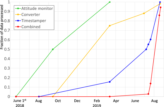
Figure 12. Progress of each data processing step and the combined data processing (first version).
Download figure:
Standard image High-resolution image4.2. γ-Ray Event Timestamps
The track timestamp was reconstructed by fitting a continuous track between the static interface stage and the first stage, between the first stage and the second stage, and between the second stage and the third stage, with track angle and position matching, and the position of the stages allowed to vary (see Takahashi et al. 2010). γ-ray events were combined with the track timestamp data. γ-ray events were followed down to the bottom of the converter and connected to the static interface stage of the timestamper. Track timestamping was applied independently to each track. We required that the events had at least one track with a single timestamp. In most events, only one track has a proper timestamp due to inefficiencies in following tracks down to the bottom of the converter and track registration over all the stages. The main reason for inefficiencies was low momentum in the present analysis. We took a single timestamp of the sole track as an event timestamp in these cases. For events that had two tracks with a single timestamp each, we assigned the average timestamp to the event timestamp. We focused on the observation of the Vela pulsar ("Vela observation"). Figure 13 shows the timestamp agreement between two tracks with a single timestamp each for an event in a data processing area. Of 4125 events, 3946 were obtained within ±5 s, with a standard deviation of 1.18 s. Therefore, a timestamp purity of 98%  and a timestamp resolution of 0.84 s (1.18/
 ) were achieved for the γ-ray event timestamping as well as for the other data processing areas.
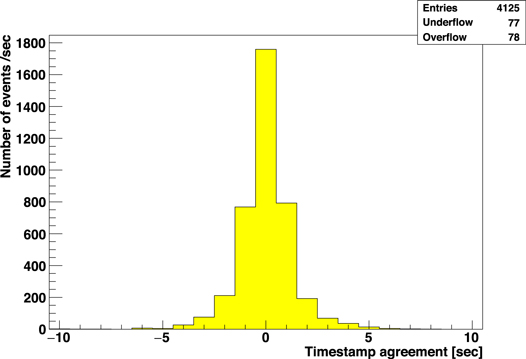
Figure 13. Timestamp agreement between two tracks with a single timestamp each for an event in a data processing area (unit 4, area 5–8).
Download figure:
Standard image High-resolution imageBased on the first version of the γ-ray event timestamping, improvements were made as follows. By taking into account information on the first stage of the multistage shifter with 40-minute timestamps, the connection inefficiency between the bottom film of the converter and the static interface stage of the timestamper was improved. Without 40-minute timestamps, the track connection efficiency between the bottom film of the converter and the static interface stage of the timestamper degraded due to the accumulation of tracks over the entire period from assembly to disassembly. As a result, the timestamped γ-ray event count was improved by nearly 20%. Fake γ-ray events, which were poor reconstructions of hadronic interactions in the converter, were reduced by more than 10% for the γ-ray events. To achieve further improvements, a pilot study was done of γ-ray events with multiple timestamp tracks. By uniquely determining multiple timestamps with a simple minimum χ2 method with differences in position and angle for the track reconstruction in the timestamper, we identified potential for a 10% improvement in the timestamped γ-ray event count, including a timestamp impurity of 2%.
Figure 14 shows the γ-ray event rate as a function of time for all units and areas, for the duration of the Vela observation. Uniform γ-ray event timestamping was achieved for the duration of the Vela observation.
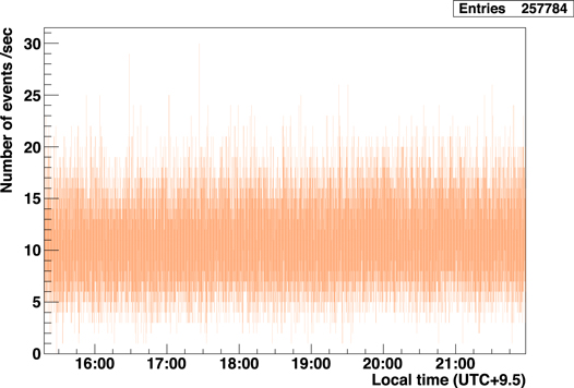
Figure 14. γ-ray event rate as a function of time for all units and areas, for the duration of the Vela observation.
Download figure:
Standard image High-resolution image4.3. Identification of Cosmic-Ray-induced Events
γ-ray events at balloon altitude include γ-rays generated by hadronic interactions in the converter and γ-rays generated by electrons (hadron- or electron-induced γ-rays). Flight data analysis of the 2011 balloon-borne experiment revealed hadron- or electron-induced γ-rays based on fully combined converter–timestamper analysis (Takahashi et al. 2015). Hadron- or electron-induced γ-ray identification not only allows a reduction in the background but can also be used for calibration (γ-ray direction, timing, energy, polarization, and detection efficiency). In the present analysis, we performed hadron-induced γ-ray identification based on the timestamper data. The timestamper data have information on track position and angle as well as timing. In the present analysis, the converter data were only used to determine which tracks were γ-ray event tracks in the timestamper. To identify hadron-induced γ-rays, track vertices were reconstructed as hadronic interactions using track coincidence with their position, angle, and timing. Then, γ-ray events were linked to the hadronic interactions based on their position, angle, and timing. The multiplicity of hadron interactions was required to be at least two tracks, not including the tracks of γ-ray events, in order to lower the threshold as much as possible. Figure 15 shows a result linking hadronic interactions and γ-rays. A coincidence peak was clearly detected, above a random chance coincidence. A total of 46% of the γ-ray events were identified as hadron-induced γ-rays within ±3 s (in part including the remaining poorly reconstructed hadronic interactions in the converter in the 2018 flight data analysis), which includes a 5% chance coincidence to misreconstruct hadronic interactions or to misidentify an independent γ-ray as associated with hadronic interactions.
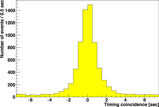
Figure 15. Timing coincidence for γ-rays linked to hadronic interactions in the data processing area (unit 4, area 5–8).
Download figure:
Standard image High-resolution imageThis 5% chance coincidence can be reduced by combination with the converter data due to a tighter coincidence with their position and angle. With the converter data, hadronic interactions can be confirmed in the converter. In addition, by using the confirmed track vertex positions and γ-ray conversion points, the extrapolation distance can be shortened and the association of γ-rays with the hadronic interactions can be made more reliable. In the present analysis, the fraction of substantial identifications was 41% (0.46 – 0.05). There is an identification loss of 7% associated with the edges of the data-processing area of the timestamper, estimated from the position distribution. The emulsion films of the timestamper were scanned with 4 × 3 divided areas with overlaps due to the working stroke of the HTS. In the data processing, scanned areas were merged to 1 × 3 with an overlap region. In the present analysis, for merging four scanned areas into one, it is only necessary to fit two adjacent scanned areas with an overlap region. This is the simplest way for merging. On the other hand, for merging 4 × 3 scanned areas into one, it is necessary to fit 12 scanned areas with 17 overlap regions in self-consistent and optimal position relations across all the areas. In principle, this is possible. By merging 4 × 3 scanned areas into one with more merging studies or developing a scanning system with larger working stroke, a seamless data area can be produced. This loss can be eliminated by using a seamless data area. Thus, the identification fraction can be increased to 44% (0.41/(1 − 0.07)).
In addition, Figure 16 shows the identification fraction as a function of the track multiplicity threshold. By lowering that threshold from two to one, combined with the converter data, the identification fraction can be increased to 50%–60%. Moreover, a pilot study of subsamples has been undertaken to identify electron-induced γ-rays. The identification fraction of electron-induced γ-rays was 4%, with a negligible chance coincidence based on timestamper data with converter confirmation. The combined identification fraction can be increased to ∼60%. The identification fractions are summarized in Table 2.
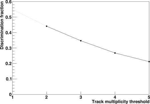
Figure 16. Identification fraction as a function of the track multiplicity threshold. The dots and solid line represent the identification fraction minus the chance coincidence, corrected for processing edge losses. The dashed line represents the prediction for a track multiplicity threshold of one.
Download figure:
Standard image High-resolution imageTable 2. Identification Fraction
| Substantial identification fraction | 0.41 |
| Expected identification fraction | (combined) |
| Edge loss elimination | 0.44 |
| Track multiplicity threshold set to one | 0.5–0.6 |
| Electron-induced γ-ray identification | ∼0.6 |
Download table as: ASCIITypeset image
4.4. γ-Ray Arrival Directions
γ-ray arrival directions were reconstructed for the timestamped γ-ray events combined with reconstructed attitudes from the star cameras. The highest-frequency motion was represented by the rotation of the gondola around the polar axis of the detector, with an average frequency of 03 s−1. The frequencies of other motions, such as pendulum and diurnal motions, were orders of magnitude smaller. The γ-ray timestamp resolution was 0.84 s. The γ-ray incident polar angle in the detector was ≤45°. Thus, the precision of the γ-ray arrival direction from the attitude determination was ≤018. Figure 17 shows the reconstruction fractions of the γ-ray arrival directions as a function of time. Although a minor lack of reconstruction fractions is seen (in part because of inefficiencies in attitude reconstruction), an overall high fraction of 99% was obtained over the entire duration of the Vela observation.
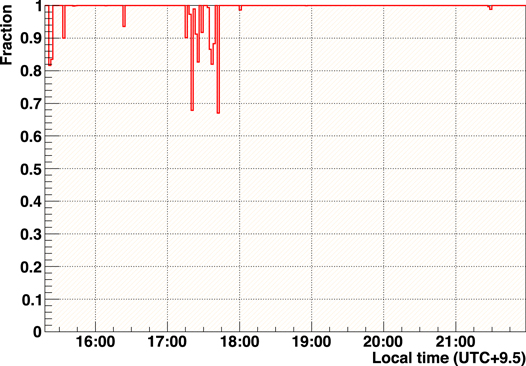
Figure 17. Reconstruction fraction of γ-ray arrival directions as a function of time.
Download figure:
Standard image High-resolution image4.5. Summary of the Number of Events
Table 3 summarizes the number of events left after each process explained above. Based on timestamping, γ-ray events were selected for the duration of the Vela observation. Most γ-ray events outside of the Vela observation period were recorded in the emulsion during the period of preparation and the need to wait for suitable wind conditions for 42 days in the hangar on the ground (540 m above sea level). Events were also rejected owing to accumulation of γ-ray events before and after the Vela observation (duration 6.7 hr) during the 10.7 hr flight, including the 2.7 hr ascent and descent phases during the total flight time of 17.4 hr. By simply using timing information, off-time events were removed, reducing the event count by a factor of 22.2. For "Hadron-induced γ-ray rejection" in Table 3, the number of events was reduced by a factor of 1.9 by rejecting hadron-induced γ-rays (partially including the remaining poorly reconstructed hadronic interactions in the converter during analysis of 2018 flight data) based on timestamper data. The data-processing areas in the timestamper have mutual overlaps. These create double-counted events for a single event in the overlap regions. The double-counted events were defined ("Consolidation of double-counted events"). "Directed" means events reconstructed for γ-ray arrival directions with attitudes from the γ-ray event timestamps.
Table 3. Summary of the Number of Events Left after Each Process
| Number of Events | Reduced Fraction | |
|---|---|---|
| (× 105) | ||
| γ-ray candidates | 57.61 | |
| Vela observation | 2.58 | 0.96 |
| Hadron-induced γ-ray rejection | 1.38 | 0.46 |
| Consolidation of double-counted events | 1.34 | 0.03 |
| Directed | 1.33 | 0.01 |
Download table as: ASCIITypeset image
4.6. Directional Analysis
A γ-ray angle with respect to the axes of each film of the converter (in the converter film coordinates) was reconstructed in the converter by using electron and positron track angles measured immediately beneath the conversion point and weighted by each momentum. The γ-ray angle in the converter film coordinates was corrected to a γ-ray angle in the converter unit coordinates with respect to the axes of the alignment film by using tracks penetrating from the alignment films to the converter. The alignment films were mechanically supported with a flatness of ∼01 and located at the top of the converter. The correction was fine-tuned using penetrating tracks, i.e., heavy ionization tracks such as those from helium nuclei accumulated during the flight with high momentum, yielding good linearity.
To align the converter units, as well as the units and the star cameras, relative angles were measured on the ground by a 3D coordinate measurement instrument, FaroArm(R), with better than ∼01 precision. After closing the vessel shell, pressurizing the vessel and packing the gondola, the mounted angles of the converter units and star cameras with respect to the coordinates defined by FaroArm(R) measurements moved by ∼1°, as monitored by the star cameras on the ground and during the flight. During the Vela observation, the mounted angles were stable to within 002, as monitored by the star cameras. Therefore, by using the flight data of the star cameras for the duration of the Vela observation, the mounted angles were adjusted to within 002 between the star cameras to achieve an even displacement of the converter units.
Based on these angles, γ-ray arrival directions were plotted in celestial coordinates. An excess associated with the position of the Vela pulsar within ∼1° was detected. To understand this angular spread, we carefully checked angular displacements from the Vela pulsar for a given detector (γ-ray telescope, Figure 18). In the detector's angular parameter space, the effect of the source structure can be eliminated because of a significant rotation of the detector (in celestial coordinates) during the flight. Figure 19 shows the γ-ray angular displacements from the Vela pulsar in the detector's X and Y directions. Offsets caused by the tilt of the detector's polar axis in the X and Y directions were corrected for. Figure 20 shows the γ-ray angular displacements from the Vela pulsar in the transverse (lateral, L) and longitudinal (radial, R) directions in the detector's angular parameter space. The lateral direction is correlated with rotation around the detector's polar axis. The radial direction is correlated with expansion/contraction of the detector's polar axis. They exhibit offsets that follow the polar angle of the γ-ray in the detector. The rotation and expansion/contraction determined from the lateral and radial directions were corrected for. We thus corrected the rotation, expansion/contraction, and tilt of a detector's polar axis with a scale of 1° for each unit.
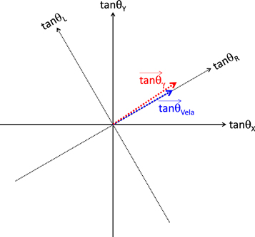
Figure 18. Schematic view of a detector's angular parameter space.
Download figure:
Standard image High-resolution image
Figure 19.
γ-ray angular displacements from the Vela pulsar in the detector's X (left) and Y (right) directions before (top) and after (bottom) correction (unit 3). The unhatched regions correspond to the tolerance of the correction (roughly corresponding to ±15).
Download figure:
Standard image High-resolution image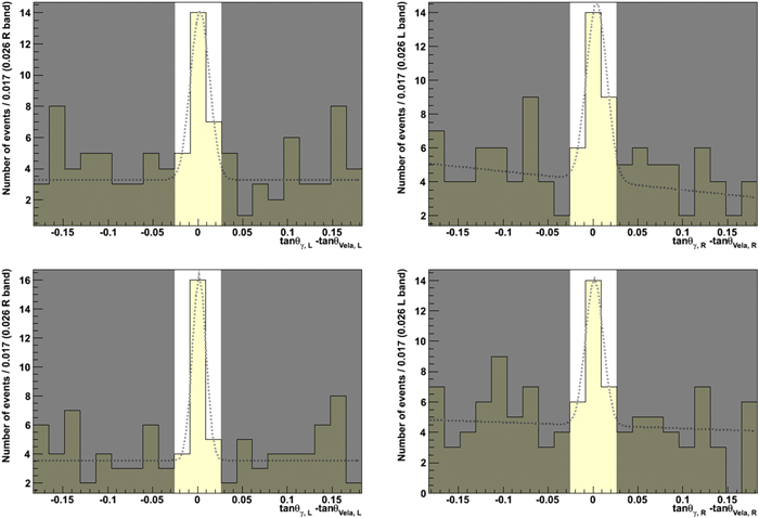
Figure 20.
γ-ray angular displacements from the Vela pulsar in the lateral (left) and radial (right) directions in the detector's angular parameter space before (top) and after (bottom) correction (unit 1), where  and
and  . The unhatched regions correspond to the tolerance of the correction (roughly corresponding to ±15 at
  ).
).
Download figure:
Standard image High-resolution image4.7. Spectral Energy Distribution
The spectral energy distribution of the Vela pulsar was derived. The observed number of signal events was obtained from the on-source region (a circle of 1° radius centered on the Vela pulsar), from which an off-source region (3°–5° radius) was subtracted. In addition, we estimated the transmittance through the residual atmospheric depth, the projected area as a function of incident polar angle, the conversion fraction in the converter, the detection efficiency, the energy measurement efficiency, the followed-down efficiency, the timestamp efficiency, the attitude efficiency, the on-source region efficiency, and the energy migration for each energy, incident polar angle, and time for the duration of the Vela observation using flight data and simulations.
5. Results
Figure 21 shows a post-correction count map in equatorial coordinates centered on the Vela pulsar. Figure 22 shows the squared radial angular distribution (θ2) centered on the Vela pulsar. The inset shows the background-subtracted squared radial angular profile (θ2) based on the number of events in the θ2 range from 0.5 to 5 deg2, assuming a uniform distribution. A clear excess is apparent at the Vela pulsar's position. By taking account of background fluctuations following a Poissonian distribution equal to or larger than the excess in the source region (θ < 042), the background-only null hypothesis was rejected with a p value of 2.3 × 10⁻¹⁰ (a simple on–off technique). The p value corresponds to 6.2 standard deviations, assuming a Gaussian probability distribution. The Li–Ma statistical significance (Li & Ma 1983) was also calculated, at 6.1 standard deviations. Therefore, we conclude that γ-rays from the Vela pulsar were robustly detected with a significance of 6σ (>80 MeV). A 68% containment radius of  deg was obtained. The uncertainties quoted on the 68% containment radius are statistical errors. Nearly symmetrical statistical errors were projected onto the containment radius using a cumulative curve. The radius can be improved by additional analysis to reduce scanning systematics, which contributed the major uncertainties in the current analysis.
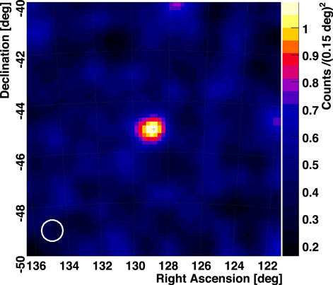
Figure 21. Smoothed count map for energies above 80 MeV in equatorial coordinates (J2000) centered on the Vela pulsar. The count map has been smoothed with a 5 × 5 weighted averaging filter. The white circle at bottom left represents the point-spread function (68% containment radius). The position of the Vela pulsar is marked with a cross.
Download figure:
Standard image High-resolution image
Figure 22. Squared radial angular distribution (θ2) for energies above 80 MeV centered on the Vela pulsar. Inset: background-subtracted squared radial angular profile (θ2). Points with error bars represent the data. The dashed curve represents a simulated point-source profile.
Download figure:
Standard image High-resolution imageA simulated angular profile is also shown in the inset of Figure 22. A signal profile was simulated with a point source using GEANT4 (10.6.p2, Agostinelli et al. 2003; Allison et al. 2006, 2016). According to the observed energy distribution, the events were generated through multiple Coulomb scattering events and angular measurement errors. The angular measurement error σ was derived from the data. The criteria for selection and reconstruction were the same as for the real data. The signal profile was normalized by the number of events in the θ2 range from 0 to 0.5 deg2. The angular profile of the data is well reproduced by the simulation. The 68% containment radius in the simulation is 055, which is compatible with the data. The angular profile of the data is consistent with a pointlike source. This result is compatible with previous observations (Abdo et al. 2009, 2010a, 2010b; Pellizzoni et al. 2009, 2010; Grondin et al. 2013).
Here, we achieved the highest imaging resolution in this energy regime to date.
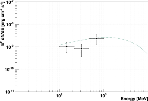
Figure 23 shows the derived spectral energy distribution for the Vela pulsar. Figure 23 also shows the best-fitting curve modeled by a power law and hyper-exponential cutoff based on Fermi-LAT observations (Abdo et al. 2010a). The spectral energy distribution is in good agreement with previous observations (Abdo et al. 2010a). Measurement errors are dominated by statistical errors.
Figure 23. Spectral energy distribution (dots with bars) for the Vela pulsar. The vertical bars represent statistical uncertainties. The horizontal bars represent energy intervals. The dotted curve represents the best-fitting model based on a power law and hyper-exponential cutoff using Fermi-LAT observations (Abdo et al. 2010a).
Download figure:
Standard image High-resolution image
6. Summary and Outlook
We are developing the GRAINE project, involving 10 MeV–100 GeV cosmic γ-ray observations with a high angular resolution (5'/008 at 1–2 GeV) and a polarization-sensitive emulsion telescope with a large aperture area (∼10 m2) for repeated long-duration balloon flights.
In 2018 April we performed a balloon-borne experiment with a 0.38 m2 sensitive area and 17.4 hr flight duration in Australia, including 6.7 hr of Vela observations. Significant improvements were achieved compared with a 2015 balloon-borne experiment, with an increase in effective area × time and a reduction in the background, by a factor of 5. This experiment was undertaken to demonstrate the overall performance of the telescope based on detection and imaging of a known γ-ray source, the Vela pulsar.
Finally, we achieved a robust detection of the Vela pulsar, with a significance of 6σ for energies above 80 MeV. We obtained a 68% containment radius of 042. The resulting angular profile was consistent with that of a pointlike source. With more exposures, we can assess the extended morphology of the source, the Vela-X pulsar wind nebula, with the highest imaging resolution ever attained. Moreover, a higher angular resolution can be achieved by moving to a higher energy regime. In addition, with a higher timestamp resolution, e.g., milliseconds, phase-resolved analysis can be performed for observations of nonpulsed emission and phase-correlated polarization. Phase-resolved analysis allows us to select emission in the off-pulse region (40% of an 89 ms period) where the steady component, the Vela-X pulsar wind nebula, is expected to be present based on previous observations (Abdo et al. 2009, 2010a, 2010b; Pellizzoni et al. 2009, 2010; Grondin et al. 2013). The derived spectral energy distribution is consistent with previous measurements. We achieved the highest imaging resolution for the Vela pulsar to date and validated the operation of the emulsion γ-ray telescope with the highest angular resolution in this energy regime.
Based on the experience and results of the 2018 balloon-borne experiment, we aim to continue scientific observations by expanding the sensitive area and flight duration of repeated balloon flights. To achieve a 10 m2 sensitive area, we need to achieve mass production of emulsion films (a total of 10 m2 × ∼100 films), and develop a large and lightweight multistage shifter (less than 1 ton with a 10 m2 sensitive area) and a high-speed emulsion scanning system (∼1000 m2 emulsion film scanning in total). To achieve 01 or higher angular resolution, we need to procure a high-precision multistage shifter (0.1 s or higher timestamp resolution) and systematic precision measurements for γ-ray events. To achieve a low energy threshold down to ∼10 MeV, we need to develop a thin multistage shifter (a total of ∼1 g cm−2 and ∼10−2 radiation lengths, for separations of less than ∼500 μm between stages). To achieve the above, we are developing an emulsion film production facility, a roller-driven multistage shifter, a next-generation scanning system, and a precise measurement system. The pressure vessel gondola will simply be expanded from the one used in 2018. A racetrack-shaped pressure vessel ring (Figure 4) will be expanded to a length of ∼8 m along the major axis with a minor-axis length of ∼1.5 m, corresponding to the diameter of the cylindrical body. It will be arranged in two parts. The 2018 data processing was limited by the data processing of the timestamper. In the latter stage of that processing, we achieved a data processing rate of 40% per month, corresponding to a data processing rate of 0.15 m2 timestamper area per month. In addition, by increasing the processing efficiency and increasing the parallelization rate of the processing, we can achieve an improvement by a factor of 5–10. The data processing can be performed reasonably well.
For high-energy γ-ray polarization, there have been no significant observations, past or present (AGILE, Fermi-LAT and so on), because of technical difficulties. The azimuth of the electron pair plane weakly correlates with the direction of γ-ray polarization. It is difficult to measure the azimuth because of a tiny opening angle of an electron pair. The nuclear emulsion films can measure the azimuth by precisely tracking the creation of an electron pair and suppressed multiple Coulomb scattering. Therefore, the emulsion γ-ray telescope can observe the γ-ray polarization. The emulsion γ-ray telescope can pioneer polarization observations of, e.g., pulsars, AGNs, flares, γ-ray bursts, etc. The minimum detectable polarization at 3σ is close to 10% for the Vela pulsar for 700 m2 × day-flight (Takahashi & Aoki 2018), where 700 m2 × day-flight corresponds to [sensitive area] × [flight days]. For the 10 m2 sensitive area, it corresponds to a 70 day flight. At 7 days per flight, this corresponds to 10 flights. On another note, for observations of the Galactic center region, this is comparable to Fermi-LAT in point-source detection sensitivity in the energy range from several tens of MeV to several GeV for 700 m2 × day-flight (Takahashi & Aoki 2018). In addition, spatially resolved observations can be performed by the emulsion γ-ray telescope in highly confused regions at high angular resolution. In 2023, we had a balloon-borne experiment in Australia, to be undertaken by JAXA Scientific Ballooning, with a 2.5 m2 sensitive area and a flight duration of 27 hr (Takahashi 2023). We aim to achieve the largest sensitive area of any γ-ray telescope in this energy regime; observe the Vela pulsar to obtain polarization measurements (a quarter of the events will be accumulated for the minimum detectable polarization (at 3σ level) of 100%, Takahashi & Aoki 2018), higher-resolution imaging in the GeV band, a demonstration of observability below 100 MeV, and developments for phase-resolved analysis; observe the Galactic center region with the highest angular resolution to date; observe transient sources with the largest sensitive area, where we expect to observe ∼2 AGN flares, based on Fermi-LAT observations (Abdollahi et al. 2017); and observe other sources including Galactic diffuse emission in the Galactic plane region, Geminga, PSR J1709–4429, 3C 454.3, the Crab pulsar, the Moon, PKS 1510–08, W44, and the Sun.
Acknowledgments
The balloon-borne experiment was conducted by the Scientific Ballooning (DAIKIKYU) Research and Operation Group, ISAS, JAXA (PI support: C. Ikeda) with CSIRO. The final preparations and launch were done at the Alice Springs balloon-launching station managed by R. Sood and others, University of New South Wales, including a NASA hangar. The recovery was supported by D. Sullivan and others. Post-flight emulsion film processing (development) was supported by A. Bakich, K. Varvell, D. Beech, N. Ioannidis, and others at the University of Sydney. Production of the power control and other circuits, and implementation of the star cameras on the gondola, were supported by K. Matsumoto, Y. Yoshizawa, and other staff of the Technical Division, Graduate School of Engineering, Kobe University. The baffles for the star camera hood were designed and implemented by H. Hayashi, F-lab, Physics, Nagoya University. English proofreading of this manuscript was done by a professional editor. This work was supported by JSPS KAKENHI (grant Nos. 17H06132, 18H01228, and 18K13562). We would like to thank a reviewer in this journal for the careful readings and fruitful comments. And also, we would like to thank six reviewers in other journals for the careful readings and fruitful comments for two years.
Footnotes
- 6
P8R3_SOURCE_V3, total. ∼0
4 for some point-spread function subtypes. - 7
The aperture area corresponds to the sensitive area.
- 8
OP40/PE13/AL7/PE13/PE45.