
Abstract
This paper reviews recent progress in acoustic metasurfaces and the novel concept of "topological acoustic/phononics" for designing compact yet efficient acoustic devices. After a brief review of this research area and its impact on ultrasonic technologies, some of the efforts to develop highly efficient sound absorption devices using acoustic metasurfaces are introduced. A resonance-based mechanism to achieve efficient absorption in metasurface structures thinner than the wavelength of the incident sound is briefly discussed, and its extensions to a broad spectrum are highlighted. Next, a valley topological phononic system is introduced, and its applications to the design of phononic waveguides are exemplified. The band structure design for extracting topologically protected edge modes is shown together with a numerical and experimental demonstration of the robustness of phononic waveguides constructed in both acoustic and elastic regimes.
Export citation and abstract BibTeX RIS
1. Introduction
Artificially engineered subwavelength structures that respond to electromagnetic waves in ways not found in nature, called metamaterials, 1–6) have significantly broadened the range of research not only in electromagnetics but also mechanics, 7–9) acoustics 10–16) and seismology. 17,18) In particular, acoustic metamaterials have provided novel insights into the development of acoustic/elastic devices used in many industrial sectors. The ability to realize exotic responses to the incident sound, such as negative refraction, 19–21) cavity resonance 22,23) and nonreciprocal propagation, 24–26) has offered a novel design space in ultrasonic devices, including ultrasonic lenses, sound cloaking, and acoustic switches/diodes. Among these, active wavefront control and perfect sound absorption realized by acoustic metasurfaces have received much attention considering the high demand for noise isolation in architectural and automotive applications. 15,16)
Phononic crystals (PnCs), 27–29) composite structures made of materials with different elastic properties periodically arranged, have also shown promise in the design of novel acoustic/elastic materials, especially as an analogs of photonic crystals (PtCs). 30,31) The frequency band structure in the reciprocal space provides the fundamental information for designing wave propagation in the PtC/PnC. Some exotic responses to the incident sound, already mentioned above, can also be realized in PnCs by designing the band structures. A typical application of a PnC to wave-propagation control is as an acoustic waveguide. By introducing a cavity region at any place in the crystal, a localized mode appears at a frequency within a band gap that can be used for waveguide design. However, the waveguides thereby designed suffer from strong degradation at the corners and at defects along the path due to backscattering. The rapid growth of research in another topic of the present review, topological phononics, has been mainly due to this drawback of PnCs.
The emergence of topological physics based on the analogy of the electron wave function in a topological insulator 32–34) to classical wave propagation 35–40) has recently initiated a new trend in ultrasonic technology. So far, these approaches have been examined and verified mainly within the audible range (kHz) and ultrasonic waves (MHz). The ability for unidirectional propagation and/or protection against backscattering at defective areas in the path and its possible extension to the extreme ultrasonic frequency regime (GHz) are keys to the realization of the next generation of acoustic devices implemented in beyond 5G/6G information technologies.
This paper, based mainly on our recent efforts, attempts to review the research trends and progress in the design of acoustic metasurfaces and a topological physics approach for acoustic waveguide design utilizing the phase invariant of the phonon band of PnCs. As for metasurfaces, we focus specifically on a membrane type and a thin tubular type of metasurface and their application to sound absorbers, with valley topological waveguide designs being discussed as the second topic of this review.
All the numerical calculations on eigenmode analyses and the wave-propagation simulations presented in this paper were performed by solving the linear elastic-wave equations based on the finite-element method (FEM) using the software package COMSOL Multiphysics. 41)
2. Acoustic metasurfaces
2.1. Resonator-based implementation of metasurfaces
The recent attention to metasurfaces began in the context of a generalization of Snell's law 42) applied to controlling light reflection/refraction on a surface by introducing phase modulations/discontinuities induced resonantly by plasmonic nanostructures fabricated artificially on a surface. 43,44) This concept can be applied to tailoring wavefronts for sound-wave refraction, as schematically illustrated in Fig. 1. Modulation of sounds with a longer wavelength than the thickness of the metamaterial is realized, for example, by tuning the material's impedance through resonators built in the structure and by its nonuniform distribution. 10) Among the various attempts to realize such exotic acoustic properties, nearly perfect sound absorbers based on acoustic metasurfaces have attracted much attention as a simple yet powerful scheme for designing new acoustic devices for practical applications such as noise shielding. Unlike conventional sound absorbers, which rely on materials loss and/or interference with transmitted and reflected waves, metasurfaces utilize the strong wave–matter interaction of resonators to achieve perfect impedance matching at the interface as well as generate strong losses in the thin structure.
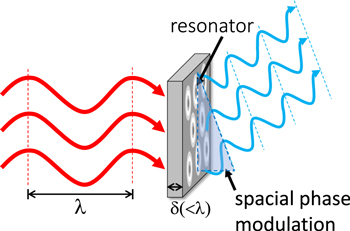
Fig. 1. Schematic of an acoustic metasurface with wavefront controllability for an incident wave
Download figure:
Standard image High-resolution imageThe (complex) acoustic impedance of the mth vibration mode Zm can be expressed in general as

where ωm and Am respectively represent the eigenfrequency and some relevant pre-factor (area per unit mass) of the mth mode in the resonator. 13,15) The highly efficient sound absorption requires that the perfect matching conditions with an incident wave from the air (impedance Z0), expressed as

are fulfilled, which is equivalent to the no-reflection condition 
2.2. Metasurface design based on a membrane resonator
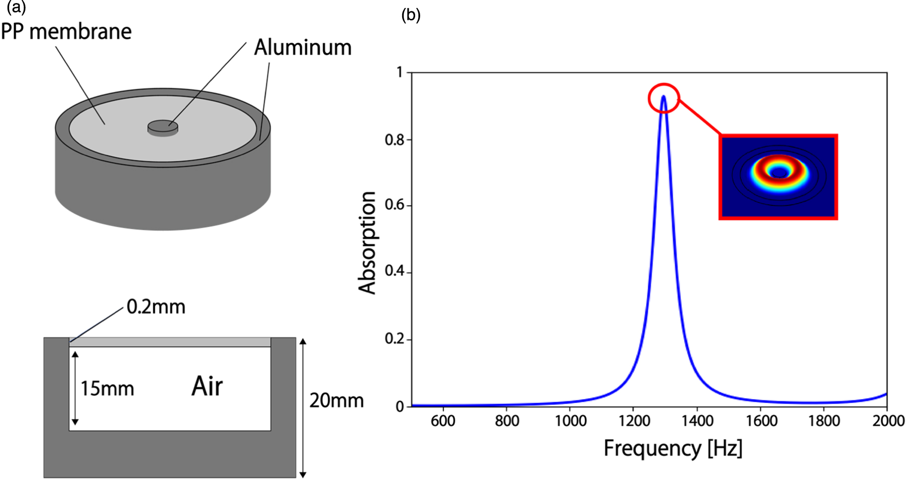
The above discussed metamaterials properties have been realized by decorated membrane resonators (DMR), 15,45) depicted in Fig. 2(a). High sound absorption occurs when the membrane and air layer vibrate to dissipate sound energy as heat. The natural vibration modes of the membrane are coupled with the air layer behind to generate a new vibration mode, which leads to efficient sound absorption. At the hybrid-mode frequency, the membrane is displaced concentrically so that a solid button placed at the center of the membrane can act as a piston to efficiently compress the air and produce large deformation of the membrane, hence leading to highly efficient energy dissipation, as shown in Fig. 2(b).
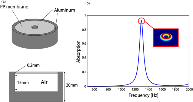
Fig. 2. (a) A schematic of a DMR and its cross-sectional view. (b) The sound absorption coefficient and the mode profile of the membrane at the peak frequency. (Adapted from Ref. 46.)
Download figure:
Standard image High-resolution imageThe high efficiency for sound absorption of a DMR is achieved by the hybridization of vibration modes in the membrane and the backing air layer in the DMR. The (complex) acoustic impedance of the hybridized vibration mode can be expressed as

In this expression

and  are the impedance of the membrane and of the air layer in the DMR, respectively. Here

 , and
, and  represent the adiabatic index of air, the average pressure of the incident wave, the thickness of the air layer, and the angular frequency of vibration. The membrane impedance
  involves the dissipation coefficient
  and mode-dependent parameters, i.e. the angular frequency
  and an effective mass density
  of the mth mode that is a weighted average with displacement of the mode. Highly efficient sound absorption occurs at the perfect matching conditions of the hybrid mode with an incident wave, as expressed again in Eq. (2).
As an example, the lowest two membrane modes generate a hybrid mode, which can be expressed approximately as
where  are the frequencies of the hybrid mode and the ith membrane mode, and the average effective mass density of the modes, respectively. In Fig. 3, two-mode hybridization is demonstrated numerically using the FEM and compared with the frequency predicted analytically. The circular membrane made of polypropylene with a diameter of 30 mm and thickness of 0.2 mm possesses the lowest concentric eigenmodes at f1 = 586 Hz [(0,1) mode] and f2 = 2279 Hz [(0,2) mode] for the peripherally fixed condition. By giving a proper value for
  one can approximately obtain the frequency for a hybrid mode via Eq. (5) to be 1193 Hz (fh), whereas FEM calculation gives 1120 Hz in the case of an incident pressure (p) of 1 Pa. It should be noted that there is a non-concentric mode [(1,1) mode] between f1 and f2. However, this mode does not contribute to the generation of the sound-absorbing mode as its average displacement vanishes. Thus, it is essential to control the number and position of the individual resonance modes of the membrane in order to properly design the absorption spectrum.
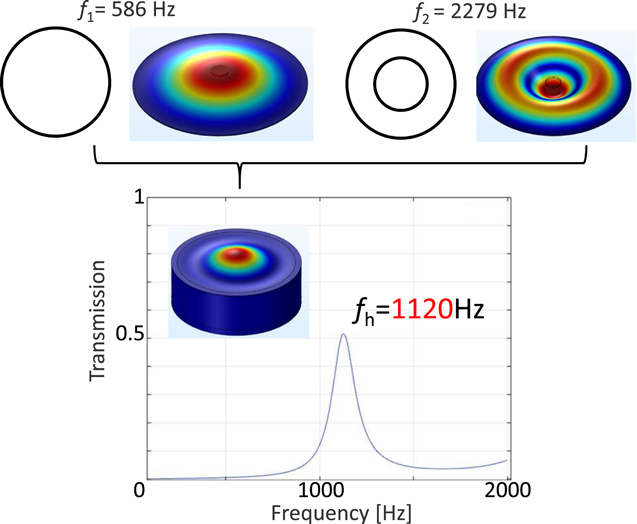
Fig. 3. An example of hybrid-mode generation. The first and second fundamental eigenmodes, with frequencies of 586 Hz and 2272 Hz, are coupled with an air layer, leading to the generation of a hybridized mode at 1120 Hz, which is approximately predicted by Eq. (5).
Download figure:
Standard image High-resolution imageDespite the nearly 100% sound absorption at the resonance frequency of the DMR, the very narrow spectrum hampers the application of the design concept to practical sound insulation, where a broader absorption spectrum is needed for efficient sound shielding. 47) We have recently proposed a novel metasurface structure that can exhibit a broader absorption spectra. 46) Our approach is based on the multiplication of membrane modes by simply introducing an asymmetry in the membrane shape. Figure 4(a) shows designed structures with dimer and trimer shapes of the circular membranes, along with their absorption spectra obtained by FEM simulations. The results show multiplexing and broadening of the absorption peak with the proposed DMR structures. This approach to broadening the absorption spectra is validated by experimental measurements. Figure 4(b) depicts three-dimensional (3D) printed DMR structures with dimer and trimer membranes. Their absorption spectra for an incident wave are also plotted in Fig. 4(b). It has thus confirmed that our simple approach is effective at overcoming the original drawback of DMR, namely its extremely narrow absorption spectrum.
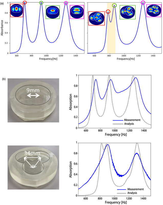
Fig. 4. (a) Sound absorption and mode diagram with dimer (left) and trimer (right) membrane structures. (b) Fabricated structures (left) and absorption spectra (right) for the respective structures in numerical simulations and experimental measurements. (Adapted from Ref. 46).
Download figure:
Standard image High-resolution image2.3. Metasurface design based on a split-tube resonator
Although the membrane resonators exemplified above have been proved to be effective, an absorption function in the frequency range below than 1000 Hz is desired for metasurfaces in practical applications such as environmental regulation of traffic noise. A low-frequency tunable acoustic absorber based on split-tube resonators was originally proposed in order to meet such a demand. 48) The tubular resonator of an elliptic cylinder with a side cut was examined; polylactide (PLA) was adopted a the base material in order to reduce the total weight of the structure. An aluminum plate placed behind the tube has the role of reflecting sound waves that resonate with the sound absorber, and also prevents sound transmission. Figure 5(a) shows the basic structure (insets) and absorption coefficient of the single split-tube resonator. The wavelength of the 516 Hz sound wave, the sound absorption peak in Fig. 5(a), was about 660 mm, whereas the thickness of the sound-absorbing structure, including the split-tube and the aluminum plate, was 25 mm. A high sound absorption characteristic was thereby demonstrated even for low-frequency sounds, for which sound absorption is generally difficult due to the large difference in size between the wavelength and the structure. The position of the resonance peak can be estimated from the elastic vibration of the split-tube coupled with the air layer in the tube as a Helmholtz-like resonance, as schematically illustrated in Fig. 5(b). Efficient absorption occurs based on the conversion of sound energy into heat energy through the hybrid resonance.
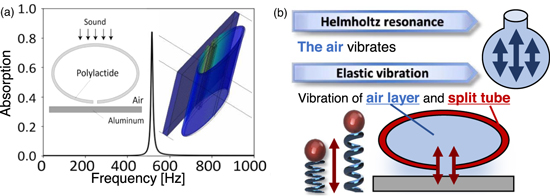
Fig. 5. (a) Cross-sectional view, absorption spectrum, and resonance mode at 516 Hz of a split-tube. (b) A schematic of the hybridization mechanism of the elastic vibration of the tube with the air layer in the tube.
Download figure:
Standard image High-resolution imageDespite achieving nearly 100% sound absorption at relatively low frequencies, the sharp peak at the resonant frequency hampers the utilization of the structure in practical applications that have ambient sound environments with relatively wide frequency spectra. To solve the problem of the narrow frequency spectrum, we again adopted the method of superposition of peaks by multiplexing split tubes of different sizes. 49) By numerical simulation, we examined the dependence on the number of layers of the tube from two through six. From the results of each multiply layered tube, two types of sound absorption peaks were obtained: a single-mode sound absorption peak in which each tube vibrates nearly independently and a hybrid-mode sound absorption peak in which all the layers vibrate. Figure 6 reveals that the sound absorption peaks due to the single vibration modes appear at frequencies in the frequency range lower than 495 Hz, whereas the peaks at frequencies higher than 495 Hz are attributed to excitations of the hybrid modes. Thus, multiple mode generation can be demonstrated by a thin split-ring tube via hierarchical hybridization of resonance.
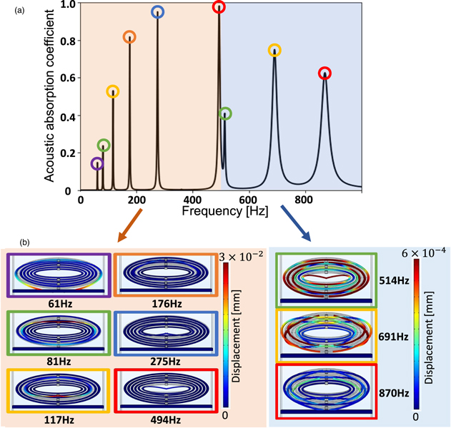
Fig. 6. (a) The sound absorption spectrum of six-layer split tubes. (b) The mode shapes and displacements at each corresponding peak in the spectrum. (Adapted partially from Ref. 49).
Download figure:
Standard image High-resolution image3. Topological phononics
3.1. Topology in acoustic/elastic systems
Another topic discussed in this review is the topological physics approach to designing acoustic/elastic-wave devices. Predictions and discoveries concerning the spin Hall effect 50,51) and topological insulators 52,53) have stimulated the search for analogous topological states in classical systems such as light, 35–37) sound 38–40) and mechanical waves, 39) especially after the Nobel prize in physics was awarded to three theoretical founders of topological physics in condensed-matter physics. 54)
Topological invariance in dispersion curves drawn in the reciprocal ( ) space also holds in classical systems.
36,38) We can write a wave equation of a periodic system in general form as
) space also holds in classical systems.
36,38) We can write a wave equation of a periodic system in general form as

Invoking Bloch's theorem, the nth eigenfunction can also be written as

The Bloch state  also obeys the same periodicity as the system:

The physical property of the eigenstate is characterized in part by its dispersion relation between  and
and  but also by topological quanta such as the Berry phase, defined as

where

is the Berry connection. The integrant in Eq. (9),

is called the Berry curvature. This has an analogous form to the magnetic flux in real space, given that the Berry connection has a similar physical property to a gauge-variant vector potential under a gauge transformation  The single-valuedness of
  for a given closed path defines an invariant modulo 2π of
  for the Bloch state.
As for acoustic cases, the wave equation for a scalar quantity  in a fluid (pressure) or an isotropic solid (one-dimensional displacement) can be represented in the form

where  and
and  are mass density and elastic modulus, respectively. When the system has periodicity in
  and
and  the Bloch theorem holds in its eigenstate, specifying the Bloch state
  A PnC is such a system. The dispersion relation between eigenfrequency and wave vector provides rich information helpful in designing acoustic properties, such as band gap, cavity state, and negative effective masses. Moreover, as discussed above, the characteristics of the Bloch state can also be captured by its topological features, such as the Berry phase and the Berry curvature.
When the phononic system has a band gap in its dispersion relation and has eigenstates with two different topologies near the band gap, there exist bands which show the phase transition of their band topology while the structure is continuously changed. Figure 7(a) illustrates a schematic of phononic bands and localized propagation modes (edge modes), depicted in red and blue lines, generated at the interface between bands with different phases ( ). The transmission characteristic with very small loss is obtained at the frequency within the red dashed circle in the figure due to propagation through this topologically protected state. In two-dimensional (2D) phononic structures, hexagonal symmetry is often adopted to express the edge state in the band gap. In a system with C3v
symmetry, the Brillouin zone has a hexagonal shape, and gap closing (the Dirac point) occurs at the K points. Also, the Berry curvature in the Brillouin zone of such a system has peaks at the K points. Thus, the edge modes appear in the gap near the K points, not the Γ point. Such a topological feature is called valley-topological. One can define a topologically invariant value called the valley Chern number obtained by integrating the Berry curvature around each Dirac point. If the Berry curvature at a K point has an opposite sign to the neighboring K points, as schematically shown in Fig. 7(b), it has been shown that the edge states in the gap appear at an interface between two hexagonal PnCs with the valley Chern numbers of the sign opposite to each other at each corresponding K point. Such an interface can be an efficient waveguide. In the following sections this concept is applied to the design of a topological acoustic waveguide in a phononic structure, and it is demonstrated numerically and experimentally that robust wave transmission, i.e. immune to backscattering by defects and/or corners in the waveguide, is possible even in waveguides with complex propagation paths as long as the edge mode is properly excited in the paths.
). The transmission characteristic with very small loss is obtained at the frequency within the red dashed circle in the figure due to propagation through this topologically protected state. In two-dimensional (2D) phononic structures, hexagonal symmetry is often adopted to express the edge state in the band gap. In a system with C3v
symmetry, the Brillouin zone has a hexagonal shape, and gap closing (the Dirac point) occurs at the K points. Also, the Berry curvature in the Brillouin zone of such a system has peaks at the K points. Thus, the edge modes appear in the gap near the K points, not the Γ point. Such a topological feature is called valley-topological. One can define a topologically invariant value called the valley Chern number obtained by integrating the Berry curvature around each Dirac point. If the Berry curvature at a K point has an opposite sign to the neighboring K points, as schematically shown in Fig. 7(b), it has been shown that the edge states in the gap appear at an interface between two hexagonal PnCs with the valley Chern numbers of the sign opposite to each other at each corresponding K point. Such an interface can be an efficient waveguide. In the following sections this concept is applied to the design of a topological acoustic waveguide in a phononic structure, and it is demonstrated numerically and experimentally that robust wave transmission, i.e. immune to backscattering by defects and/or corners in the waveguide, is possible even in waveguides with complex propagation paths as long as the edge mode is properly excited in the paths.
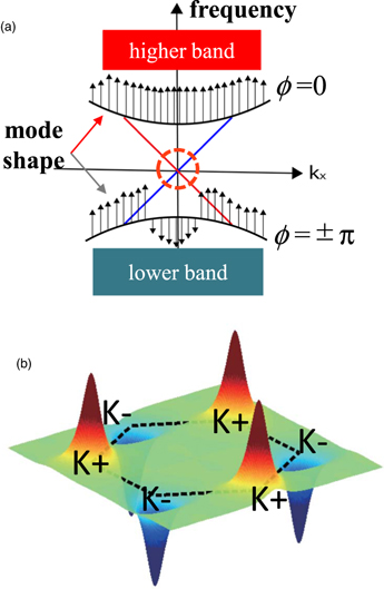
Fig. 7. (a) Schematics of topological phase transition in a phononic band and an edge mode generated at the interface between bands with different topological phases (ϕ). (b) A schematic of the Berry curvature distribution in a phononic structure with C3v symmetry.
Download figure:
Standard image High-resolution image3.2. Design of a valley topological acoustic waveguide
Many of the 2D valley topological systems that have been proposed and examined previously have C3v symmetry realized by a unit-cell structure with triangular elements. 55–58) On the other hand, we have recently proposed a new structure that can be easily fabricated yet retains C3v symmetry by using three rods with a circular cross section in the unit cell, as illustrated in Fig. 8(a). 59,60) The center of mass of the three rods is located at the hexagonal lattice points. The three rods are made of stainless steel and embedded in water. The arrangement of the three rods ensures that the unit cell has C3v symmetry, with the Dirac point at the K points, and the rotation angle α is defined as a parameter to specify the phase of the system. Figure. 8(b) shows the eigenmodes and band diagrams of the three-rod unit cell. It shows that the K+ mode and K− mode appear at the K point in the band diagram for structures of α = −30° and 30°, respectively. By continuously changing α from −30° (left) to 30° (right), the gap is narrowed and closed at α = 0° with a Dirac-like cone, exhibiting a topological phase transition where the topologies of the bands above and below the gap are flipped.
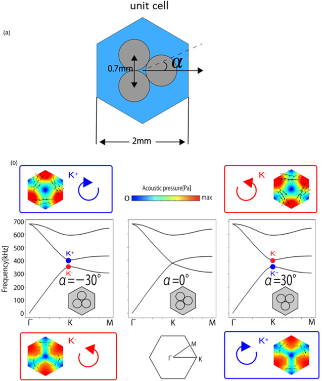
Fig. 8. (a) Unit cell structure. (b) The phonon band structure of a three-rod valley-type phononic crystal. (Adapted from Refs. 59 and 60.)
Download figure:
Standard image High-resolution imageWe construct an acoustic waveguide with a topological phononic supercell created by arranging unit cells composed of three rods with α = −30° in the lower layer and α = 30° in the upper layer. The lattice constant of the PnC structure is a = 2.2 mm. Figure 9(a) shows the band structure of a supercell with unit cells of α = −30° in the lower layer and α = 30° in the upper layer. The eigenmode analysis of this supercell reveals that the edge state appears at a frequency around 400 kHz. Figure 9(b) shows the sound pressure distribution (absolute value) in a straight waveguide with three-rod valley-type PnCs for a 400 kHz incident wave. The sound wave propagates on the boundary efficiently through the topologically protected edge mode.
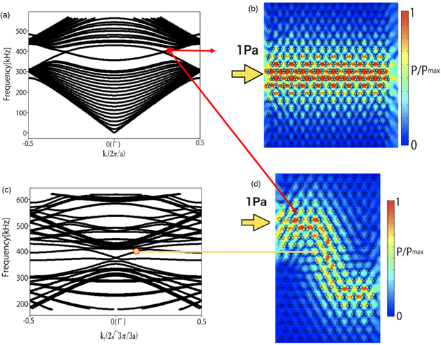
Fig. 9. (a) Band structure of a supercell combining two unit cells of α = −30° and α = 30° with the interface along the Γ–K direction. The solid red circle indicates upper band edges near the edge states, where two bands cross each other. (b) Sound pressure distribution (absolute value) in a straight waveguide for a 400 kHz incident wave. (c) Band structure of a supercell combining two unit cells of α = −30° and α = 30° with the interface perpendicular to the Γ–K direction. (d) Sound pressure distribution (absolute value) in a crank-shaped waveguide for a 400 kHz incident wave. (Adapted from Ref. 59).
Download figure:
Standard image High-resolution imageFigure 9(c) shows the band structure for the supercell, which combines two unit cells of α = −30°and α = 30° with the interface perpendicular to the Γ–K direction. Figure 9(d) shows the sound pressure distribution (absolute value) in the crank-shaped acoustic waveguide with a three-rod valley-type topological structure for a 400 kHz incident wave. The sound wave propagates on the boundary between two topologically inverted phononic structures with a crank shape.
Based on the results of the 2D FEM simulation described above, we fabricated a 3D three-rod valley topological waveguide. Figure 10(a) is a photograph of the fabricated acoustic waveguide of three-rod valley topological PnCs with a crank-shaped interface. The waveguide is fabricated by inserting stainless steel rods into a 3D printed mold. In contrast to other works based on an equilateral triangle valley-type structure, it does not require metal processing and can thus be fabricated easily. We measured sound pressure in water using the fabricated waveguide. The experimental setup in the present study is illustrated in Fig. 10(b). Figure 10(c) shows transmission in the FEM simulation and in the experiment for the crank-shaped, three-rod, valley-type topological acoustic waveguide. From Fig. 10(c), both the experimental and simulation results verified the high robustness of the valley phononic waveguide for an incident wave around 400 kHz.
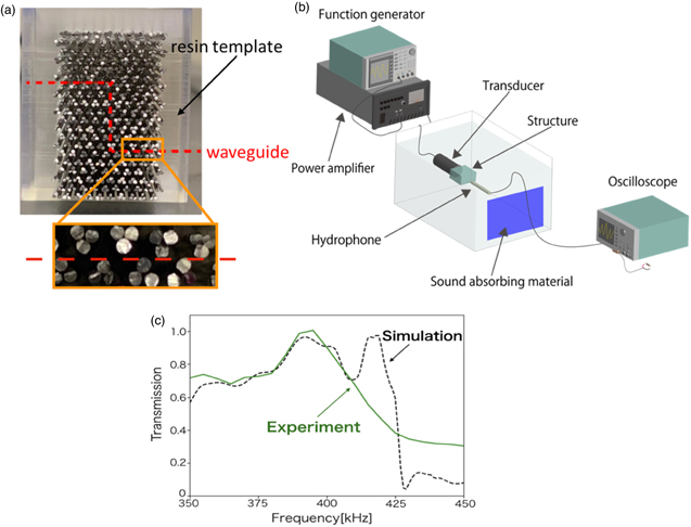
Fig. 10. (a) Crank-shaped three-rod valley-type topological acoustic waveguide fabricated in a resin template. (b) Schematic of the experimental setup. (c) Transmission spectra measured in simulation and experiment of the crank-shaped, three-rod, valley-type topological acoustic waveguide. (Adapted from Ref. 59).
Download figure:
Standard image High-resolution image3.3. Valley topological elastic waveguide
Wave propagation in the 2D acoustic systems exemplified above is inherently limited within longitudinal modes. In view of further applications, by implementing the functionality into on-chip systems, phononic systems should be designed in 3D solid-state media. Here, a topological phononic structure in a thin plate and the edge mode of an elastic wave is designed for developing an efficient elastic waveguide. The realization of next-generation mobile communication devices relies on the development not only of high-speed logic gates but also of efficient signal processing components such as surface acoustic wave (SAW) filters.
The phononic structure adopted here consists of a 3D unit cell with snowflake-shaped holes in a hexagonal grid, as illustrated in Fig. 11(a). 61) A valley-shaped band structure can be varied by changing the length of the six legs of the snowflake (Δr). These snowflake-like unit cells have been adopted in a variety of studies for PnCs as simple but highly controllable structural units in designing phonon band structures. 23,62–64)
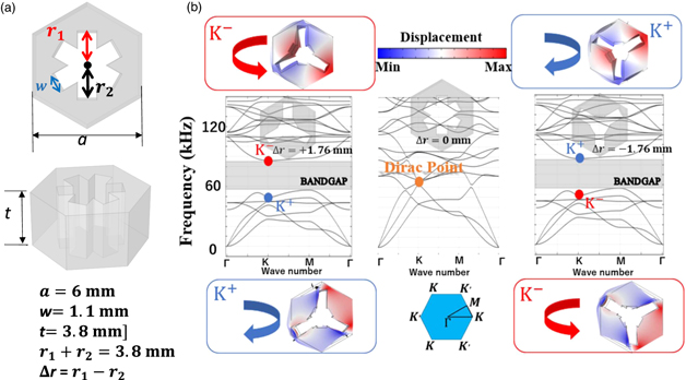
Fig. 11. (a) Snowflake-like unit-cell structure in a PnC. (b) Phonon band diagrams and eigenmodes at K points for three unit-cell structures with different Δr. (Adapted from Ref. 61).
Download figure:
Standard image High-resolution imageFigure 11(b) shows the band diagram of a phononic structure with a snowflake-shaped unit cell, revealing that the band gap opens at Δr = ±1.76 mm. Although the two eigenmodes have similar shapes, the vortex directions of the mechanical energy flow are opposite to each other. It can also be seen that the direction of the vortices changes above and below the band at Δr = 0. Since this indicates a topological phase transition, we can expect valley chiral edge states to appear around this frequency. 55) From Fig. 11(b), we can confirm that the phonon-band topological phase transition in a PnC on a thin plate occurs in reciprocal space and can be easily controlled by a single parameter Δr.
We then designed and examined a Z-shaped waveguide and its transmission properties for an incident wave. As the interface along the oblique line in the Z shape has the same type of symmetry as that along horizontal lines, these waveguides were used to assess the robustness of wave propagation against backscattering by the corners of the paths. Figure 12(a) illustrates the designed waveguides along the interfaces between phononic structure with different Δr (Δr = +1.76 mm and −1.76 mm).
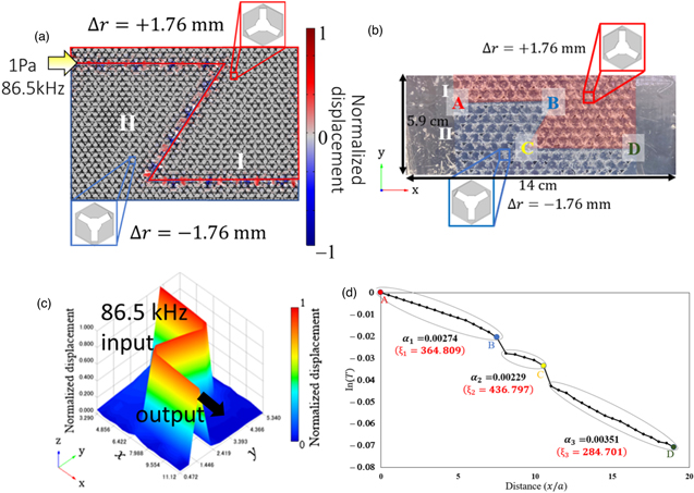
Fig. 12. Structures and displacement fields in numerical simulation for an incident wave at 84.2 kHz in Z-shaped topological waveguides between the unit cells of Δr =  1.76 mm and (b) its fabricated sample. (c) Distribution of normalized displacement, and (d) logarithmic plot of the transmittance along the path of the Z-shaped waveguide obtained by a laser Doppler measurement. The points designated by A, B, C, and D in Fig. 12(d) correspond to the points in Fig. 12(b). (Adapted from Ref. 61).
Download figure:
Standard image High-resolution imageNext, topological Z-shaped waveguides made of polypropylene were fabricated using a 3D printer, as depicted in Fig. 12(b). The induced elastic waves at the entrance of the waveguide were measured and mapped with a laser Doppler vibrometer. Figure 12(c) depicts the spatial distributions of the displacement. The large displacement was observed only along the interface regions, indicating that highly efficient wave propagation is realized as predicted in the numerical simulations.
Recently, a degradation of robustness by the presence of corners and/or structural randomness has been quantitatively evaluated in terms of the "backscattering length" ξ in valley topological photonic waveguides. 65–67) The same evaluation in terms of ξ should be valid in valley topological phononic waveguides. Figure 12(d) show logarithmic plots of the transmittance along the paths of the Z-shaped waveguides in the experiment. The values of ξ are evaluated from the negative slope of the logarithmic plot (ξ ∼ −x/logT ) for each segment AB and CD to give approximately 365 and 285, respectively. On the other hand, B and C (corners in the waveguides), have a smaller ξ (∼100) than the former. This indicates that the effect of backscattering is more pronounced in corner sections than the structural randomness in the straight sections. The attribution of lower values of the Z-shaped topological waveguide than for the straight topological waveguide is thereby shown quantitatively. Despite that, the prevention of backscattering is shown to be degraded; the present values of around 300 in the straight waveguides prove to be very efficient compared with the reported values (∼100) in valley topological photonic systems. 65,66) This may imply that SAW are more efficient in transmission than photonic circuits in utilizing topological waveguides.
Recently, further attempts have been made to control elastic waves in the ultra-high frequency regime (GHz) in thin films with PnCs. 23,68–70) Moreover, in view of further developments beyond the current telecommunication frequency (6G), nanoscale phononic design towards the THz frequency range, which may reach the atomistic level, 71,72) should be within our scope. 73) Here we preliminarily examine topological waveguides for this purpose. Figures 13(a) and 13(b) present trial designs of Z-shaped and double Z-shaped waveguides designed on GaAs substrates with micrometer- and nanometer-scale phononic structures, respectively. Also shown are the displacement fields in the FEM simulations for the incident waves depicted in the figures. It is thus revealed that topologically protected elastic waves can also be excited and propagate efficiently along the interfaces. These analyses clearly indicate that the design scheme based on the band analysis to find topological phase transition is effective even at the nanometer scale.

Fig. 13. Unit-cell structures and out-of-plane displacements in finite-element simulations of topological phononic waveguides fabricated in GaAs membranes with (a) micrometer-scale and (b) nanometer-scale lattice constants. The incident-wave frequencies to the waveguide are (a) 0.78 GHz and (b) 0.91 THz, respectively.
Download figure:
Standard image High-resolution image
4. Conclusions
This paper has introduced some topics concerning recent advances in acoustic metasurfaces, and in topological phononics/acoustics, which were partly presented at the 43rd Symposium on Ultrasonic Electronics (USE2022) and its Proceedings volume. 74) The design scheme for resonator-based metasurfaces and its applications to sound-absorbing structures (the DMR and the split-tube resonator) are proposed, emphasizing the possible broadening by multiplexing of their resonant modes. The metasurface approach can be specifically useful for developing noise-shielding material, used, for example, in electric vehicles in which light weight yet high performance in noise shielding is required. As for topological phononics, highly efficient transmission in topological waveguides was demonstrated by both numerical simulations and experiments. The band topology was proven to be a powerful tool for designing acoustic/elastic waveguides implemented especially in SAW devices. Regarding the actual design, however, the band design still involves trial-and-error processes, especially for searching the topological phase transition that is a key to constructing the interface where the topologically protected edge mode appears. Theoretical and/or computational methodology to systematically identify the topological index (Berry phase) for arbitrary PnC structures should be developed to accelerate device development. Also, high demands are expected in the extension of the methodology presented here to higher-frequency regions for the next-generation (6G and beyond) communication era. 73) Researchers in the field of ultrasonic electronics should play a central role in responding to this demand.
Acknowledgments
I am grateful for helpful discussions, guidance, and collaborative works related to this study provided by collaborators, namely, Professors Satoshi Iwamoto, Jun Kondoh, Osamu Matsuda, Masaaki Misawa, Masahiro Nomura, Keiji Sakai, Motonobu Tomoda, Oliver B. Wright, Ken Yamamoto, and Drs. Daiki Hatanaka, Atsushi Ishikawa, and Hiroshi Yamaguchi, as well as present/former graduate students at Okayama University. This work was supported in part by the JSPS KAKENHI grant numbers JP21H05020 and JP21K18877.