Article

An Autonomous Device for Solar Hydrogen Production from Sea Water

by
Jesús González-Cobos
1,†,
Bárbara Rodríguez-García
1,
Mabel Torréns
2,
Òscar Alonso-Almirall
3,
Martí Aliaguilla
3,
David Galí
3,
David Gutiérrez-Tauste
3,
Magí Galindo-Anguera
3,
Felipe A. Garcés-Pineda
1,* and
José Ramón Galán-Mascarós
1,4
1
Institute of Chemical Research of Catalonia (ICIQ), The Barcelona Institute of Science and Technology (BIST), Av. Països Catalans, 16, 43007 Tarragona, Spain
2
Departament d’Enginyeria Química, Universitat Rovia i Virgili, Av. Països Catalans, 26, 43007 Tarragona, Spain
3
LEITAT Technological Center, C/de la Innovació 2, 08225 Terrassa, Spain
4
ICREA, Passeig Lluís Companys 23, 08010 Barcelona, Spain
*
Author to whom correspondence should be addressed.
Present address: Institut de Recherches sur la Catalyse et l’Environnement de Lyon UMR 5256, CNRS, Université Claude Bernard Lyon 1, 2 Avenue A. Einstein, 69626 Villeurbanne, France.
Water 2022, 14(3), 453; https://doi.org/10.3390/w14030453
Submission received: 15 December 2021 / Revised: 25 January 2022 / Accepted: 28 January 2022 / Published: 2 February 2022
(This article belongs to the Special Issue Immobilized Molecular Water Oxidation Catalysts)

Abstract

:
Hydrogen production from water electrolysis is one of the most promising approaches for the production of green H2, a fundamental asset for the decarbonization of the energy cycle and industrial processes. Seawater is the most abundant water source on Earth, and it should be the feedstock for these new technologies. However, commercial electrolyzers still need ultrapure water. The debate over the advantages and disadvantages of direct sea water electrolysis when compared with the implementation of a distillation/purification process before the electrolysis stage is building in the relevant research. However, this debate will remain open for some time, essentially because there are no seawater electrolyser technologies with which to compare the modular approach. In this study, we attempted to build and validate an autonomous sea water electrolyzer able to produce high-purity green hydrogen (>90%) from seawater. We were able to solve most of the problems that natural seawater electrolyses imposes (high corrosion, impurities, etc.), with decisions based on simplicity and sustainability, and those issues that are yet to be overcome were rationally discussed in view of future electrolyzer designs. Even though the performance we achieved may still be far from industrial standards, our results demonstrate that direct seawater electrolysis with a solar-to-hydrogen efficiency of ≈7% can be achieved with common, low-cost materials and affordable fabrication methods.

1. Introduction

Water is an environmentally clean hydrogen source. It is carbon-free and highly available. The electrochemical conversion of water into hydrogen and oxygen through a water electrolysis process appears to be the most promising method to produce high-quality green hydrogen on both large and domestic scales. Although water is abundant on earth, pure water is scarce because 97.5% of water is salty and only 2.5% is fresh. In total, 80% of fresh water is frozen in the icecaps or combined as soil moisture [1]. Considering that fresh water is vital for human life and that there are major access problems in large parts of the world [2], the advantage of using salty water sources as feedstock for hydrogen production seems obvious.
A first option would consist of a two-step process, with the initial treatment of seawater (distillation, reverse osmosis, etc.) to obtain pure enough water for use with current commercial electrolyzers, such as alkaline (AEL), or polymer exchange membrane (PEMEL). A recent study on the economics of direct seawater splitting with current technologies concluded that the capital and operating costs of the initial purification of seawater may be insignificant compared to those associated with the electrolysis of water [3]. However, other authors pointed out that technological developments may well change these economic considerations [4]. It is obvious that green hydrogen from seawater is likely to become a major approach, given the scarcity of fresh waters. The solution will depend on the achievements of direct electrolysis.
The direct electrolysis of seawater is still far from being realized. No electrolyzer can operate in salty environments. The expected advantages of this approach, however, are its low capital requirement, as well as the possibility of obtaining chlorine as a by-product. Indeed, chlorine could be a valuable intermediate product in industry, and it is produced on a large scale through the electrolysis of brine, among other production technologies. Around 3.9% of electrolytic hydrogen production on an industrial scale is obtained as a by-product of the chloro-alkali industry [5].
At the same time, the presence of Cl and of nascent Cl2, is a key problem for the process. The high corrosive power of seawater attacks/deactivates most electrocatalysts. Because of this, only precious platinum (Pt) and Iridium (IrO2) species have been proposed as electrocatalysts for seawater [6]. However, this approach would not help to alleviate the sea water electrolysis costs. A small number of studies concerning the use of non-precious catalysts for seawater splitting are reported briefly here, placing this study in a broad context and highlighting why it is important [7,8,9,10].
Very recently, several groups reported the excellent stability of sea water electrolysis of Prussian blue derivatives (PBs) [11,12]. These PB catalysts are robust materials in brine, which are not attacked by strong solution activity, nor by chlorine. Furthermore, the Co-Fe derivative, or cobalt hexacyanoferrate (CoHFe or CoFePB), is an excellent water oxidation catalyst in the seawater pH range [13,14,15]. Thus, we decided to develop, build and test a natural sea water electrolyzer based on non-noble metals and, in particular, on Co-Fe PB anodes, given their promising performance at laboratory scale for water electrooxidation. The purpose was to combine exclusively low-cost materials and fabrication methods, easy implementation, and the integration of solar panels to produce green hydrogen. In this article, we describe the road we took to reach this target, our decision-making rationale, and the lessons we learned when facing sea water electrolysis. Our results will be very valuable for other groups to face this very same challenge, to offer different solutions, or optimized approaches, and to solve the most important issues we encountered.

2. Materials and Methods

2.1. Synthesis of CoHFe Nanoparticles

CoHFe nanoparticles were prepared using a modified version of a protocol from a different study [16]. To prepare nanosized CoFe-PB, we used the same procedure as that detailed by Goberna-Ferrón et al. [17], but using formamide as solvent to achieve the minimum size accessible by this technique. A formamide solution of K3Fe(CN)6 (0.03 M, 50 mL, Sigma Aldrich, St. Louis, MO, USA) was instantly poured into a formamide solution of Co(NO3)6 (0.02 M, 50 mL, Sigma Aldrich), immediately forming a dark purple dispersion. The solution was kept under stirring for 2 h and the product collected by filtration. The solid material was washed by redispersion in deionized water and centrifuged at 6000 rpm. This washing/purification process was repeated three times to collect the product as a fine red-purple powder. Finally, the CoHFe nanoparticles were dried at 60 °C and then deposited on the electrode. The CoFe-PB nanoparticles were characterized by transmission electron microscopy (TEM) with a JEOL 1011 microscope operating at 100 kV and by dynamic light scattering (DLS) with a Zetasizer Ultra ZSU5700 to measure the particle size distribution.

2.2. Electrode Preparation

The PS/SiOx/FTO/CoFe-PB anodes were prepared from n-type silicon, doped with phosphorus or antimony (resistivity < 0.002 Ω·cm). The wafers were cleaned by immersion in acetone and kept for 5 min in ultrasound; they were then immersed in 1:4 HF:ethanol for 10 min followed by an mQ-water rinse. Subsequently, porous silicon (PS) was obtained through a galvanostatic process as follows. A Teflon reactor fitted with two Pt meshes was filled with a solution of 20 mL H2O, 2.5 mL HF, 25 mg KMnO4 and 60 mg Na-dodecyl sulfate. Next, 15 mA/cm2 current density was applied for 30 min in a two-electrode configuration. After anodization, the wafer was washed with water and immersed in ethanol. Finally, it was dried with nitrogen [18]. Next, a passivation process was performed at 700 °C in air for 30 min. FTO was spray-deposited following a procedure reported elsewhere [19]. In summary, a solution of SnCl4·5H2O (0.2 M) and 5% of NH4F in ethanol was sprayed on a heat PS/SiOX porous wafer (450 °C). Spray pyrolysis took place on a silicon surface, yielding a high-conductivity FTO coating [20]. Dip coating on a PS/SiOx/FTO wafer was carried out overnight in a well stirred Nano-CoFe dispersion of 1 mg mL−1 and dried in air. The electrodes were analyzed after the different synthesis steps by environmental scanning electron microscopy (ESEM) with a QUANTA600 microscope from FI company operating at 20 kV.

2.3. Electrochemical Characterization

Seawater was collected from the Mediterranean Sea, from a beach near Barcelona, Spain, with an average pH of 8, and it was used without further purification. The electrochemical experiments were performed at room temperature and atmospheric pressure in different cell configuration. The first electrochemical tests were carried out in three-electrode configuration for anode optimization. In this case, PS/SiOx/FTO/CoFe-PB was used as working electrode, Pt mesh as counter electrode and Ag/AgCl, 3.5 M KCl as reference electrode. Seawater electrooxidation was studied by linear sweep voltammetry and chronoamperometry measurements by using a Biologic SP-150 potentiostat/galvanostat. All potentials measured in the three-electrode cell were iR-corrected by the current interruption technique.
Next, PS/SiOx/FTO/CoFe-PB was tested in two-electrode configuration, at laboratory scale, by using carbon felt as cathode. The carbon felt was pre-treated at 450 °C in air atmosphere overnight for pollutant removal and activation. In these tests, different electrode areas, anode-to-cathode ratios and cell volumes were explored. Finally, the anodes were applied at a large scale on the developed seawater electrolyzer prototype.

2.4. Seawater Electrolyzer Prototype

Detailed information on the design, construction and validation of the seawater electrolyzer prototype can be found throughout the manuscript and in the Supplementary Materials.
Gas product analysis was performed with an online H2 sensor (Unisense) and with a gas chromatograph (Agilent 490 microGC, Agilent Technologies, Santa Clara, CA, USA) equipped with CP-Molsieve 5A and CP-Poraplot U columns along with thermal conductivity detectors, after collecting the sample with FlexFoil gas sampling bag with a 1 L capacity. Iodometric titration of chlorine trapped in KI solution was measured following a protocol from Occupational Safety and Health Administration (OSHA) [21]. The solid precipitate on the cathode was also analyzed, after electrochemical tests on the prototype, by inductively coupled plasma-mass spectrometry (ICP-MS) with an Agilent 7500 (Agilent Technologies). Quantification was performed by interpolation in calibration curves obtained from commercial 1000 ppm standards of the elements under study (Sigma Aldrich).

3. Results

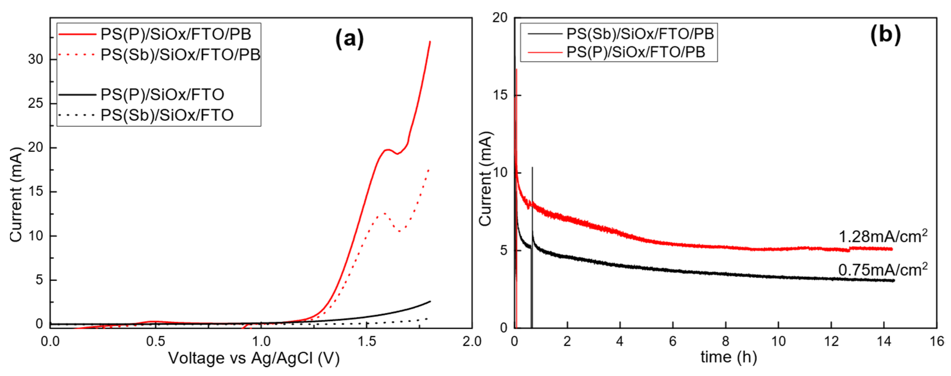
3.1. Anode and Cathode

Our first task was the synthesis of the CoFe-PB nanoparticles, which had an average particle size around 70 nm, as confirmed by TEM (Figure S1a in Section S1 in Supplementary Materials) and by DLS (Figure S1b), while it was above 200 nm in a similar synthesis procedure in which the aqueous solutions of Co-Fe precursors were used [17]. In the present work, the particle size was limited by the presence of formamide, which can be coordinated to the cobalt and suppress the further crystal growth of Co-Fe. We encourage the reader to refer to our previous work [12] for a deeper characterization analysis of these Co-Fe nanoparticles by XRD, IR and Raman spectroscopy.
The next step was the optimization of the anodes, which are the limiting part for the device. We selected highly porous supports made from n-type silicon wafers to maximize the active surface area. The PS/SiOx supports were coated with FTO through a spray electrolysis procedure to achieve high surface conductivity. Next, CoFe-PB nanoparticles were deposited by dip-coating. Figure S2 in the Supplementary Materials section shows the ESEM micrographs collected after the different synthesis steps, and Figure 1a,b shows the ESEM images that were eventually obtained on two PS/SiOx/FTO/CoFe-PB electrodes synthesized by using different Si wafers as starting materials, i.e., doped either with phosphorus or antimony, respectively. In both cases, a rough electrode surface can be observed, but in the former case, the porosity was shown to be higher due to the growing of flower-like structures. The reason seems to be related to the different pore sizes generated during the initial anodization step. With phosphorous-doped Si, much smaller pores were formed than with Sb-doped Si. While the latter allowed us to obtain macro-pores on the Si wafer (i.e., above 50 nm), the phosphorous-doped Si formed nanopores under the same synthesis conditions, which cannot be clearly detected by ESEM technique (please see Figure S2). Thus, more defects and, therefore, higher nucleation points, are likely generated on this surface. One can therefore expect more pronounced dislocations in the deposited FTO and the formation of rougher structures with a greater superficial area.
The deposition method was optimized to ultimately offer good electrochemical performance in sea water, in terms of both activity and stability. Figure 2a shows the linear sweep voltammetry measurements carried out in a half-cell configuration with catalysts prepared from both phosphorus- and antimony-doped silicon. In both cases, an anodic peak can be observed, starting at c.a. 1.25 V vs. Ag/AgCl, which can be attributed to the electron transfer process associated with the CoIIFeIII-CoIIIFeII couple [14,19]. The resultant catalyst was shown to be active in the seawater electrolysis when the applied potential was increased further. The negligible current densities obtained with the blank electrodes, i.e., PS(P)/SiOx/FTO, also confirm the genuine catalytic activity of the CoFe-PB nanoparticles. Thus, one can estimate a seawater oxidation onset potential of c.a. 1.93 V vs. RHE, which corresponds to an overpotential of 0.70 V with respect to the standard oxidation potential of the H2O/O2 couple (1.23 V). This high overpotential can be attributed to the high potential required for the formation of the active catalytic phase. When comparing with research on saline water (pH 8) electrolysis using anodes based on non-noble metals, the onset oxidation potential reported herein (1.93 V vs. RHE) is higher than that shown in the only other two studies carried out in the absence of any buffer solution: (i) CoFe-layered double hydroxide supported on Ti mesh [22] and (ii) MnxW1−xOy supported on IrO2-covered Ti sheet [23], which showed an oxidation onset potential of c.a. 1.6 and 1.7 V vs. RHE, respectively. However, in these cases, simulated seawater (0.5–0.6 M NaCl) was tested while, in the present work, natural seawater without any additives or purification was employed.
Higher activity of the catalyst prepared on silicon doped with phosphorus compared with the catalyst doped with antimony can be observed in the cyclic voltammetry as well as in the chronoamperometry measurements, shown in Figure 2b. This was likely due to the higher roughness achieved on the phosphorous-doped Si support, as previously shown. The optimized anode, PS(P)/SiOx/FTO/CoFe-PB, shows a steady-state current density of 1.28 mA cm−2 at 1.65 V vs. Ag/AgCl. Although a significant decrease in the current density is observed at the beginning of the measurement, likely due to the decay of the capacitive current and the mechanical loss of weakly attached PB nanoparticles, the electrode is stable, at least, for the last 8 h monitored. The stability of the CoFe-PB/FTO catalyst under similar seawater oxidation conditions was also confirmed in a previous work by a set of post-catalytic characterization measurements including X-ray diffraction (XRD), transmission electron microscopy (TEM), energy-dispersive X-ray analysis (EDX), Raman and IR spectroscopy and inductively coupled plasma-optical emission spectrometry (ICP-OES) [12]. However, beyond the electrochemical tests we performed on three-electrode cells and on the scaled-up prototype in this study, the long-term stability of the electrode would be ideally tested in an open system with proper refreshment in the vicinity of the electrodes.
With respect to the cathode, and in an attempt to minimize costs, simple carbon felt was the material of choice. This is a black, highly macroporous, foam-like material made of carbon fibers (see Figure S3a in Supplementary Materials), used on an industrial scale as a heat and friction insulator. It is highly resistant and low in cost. Carbon is already an active material for the hydrogen evolution reaction (HER) [24,25], and the benefit of decorating it with a better catalyst was considered a drawback to keep the costs at a minimum. This can be mitigated easily by increasing the electrode area. In Figure S3b, one can observe the effect of different pre-treatment procedures on the HER activity of carbon felt in seawater. The obtained cathodic currents increased after a chemical pre-treatment (i.e., with H2SO4) and, especially, after a heating pre-treatment (i.e., 450 °C); this was likely due to enhanced hydrophilicity [26]. Furthermore, the electrocatalytic performance of the PS(P)/SiOx/FTO/CoFe-PB anode on seawater oxidation was shown to be reproducible using either Pt mesh or thermally activated carbon felt as the cathode, as observed in Figure S4. Next, the optimum anode surface-to-cathode volume ratio was determined to maximize the hydrogen productivity of the prototype. For this purpose, a home-made two-electrode cell with a volume of 3.5 L was used, which created the possibility of testing different amounts of electrodes and different distances between them (Figure 3a,b). The strongest performance was obtained with an anode/cathode ratio of 4 (Figure 3c). These measurements also allowed us to determine, in a two-electrode configuration on a low scale, a steady-state current density of 1.75 mA cm−2anode (i.e., 3.5 mA cm−3cathode) at a cell voltage of 2.7 V. This became the reference value we used in order to validate the seawater electrolysis prototype.
A first scaling-up of the electrodes was performed to evaluate the activity and stability of the larger anodes for seawater oxidation, in a 20 L batch cell under vigorous stirring, before their implementation in the prototype. Figure 4 shows the current obtained for different chronoamperometries between 1.25 and 2.7 V by using eight two-sided wafers of PS-modified electrodes decorated with CoFe-PB by dip-coating (1016 cm2 in total) and carbon felt (150 cm3, dried). The current density increased with the cell voltage in the whole range studied and the electrocatalytic performance proved to be stable, at least for a few hours. However, the steady-state current density obtained at 2.7 V, around 0.16 mA cm−2, was far below the expected value according to previous measurements using electrodes in the 4–32 cm2 range. At this point, it must be noted that the first bottleneck of the seawater electrolysis scaling-up, as is discussed below, is the anode deposition scaling-up. The dip coating method leads to heterogeneity of the CoFe-PB coatings on the electrodes, which likely has a stronger influence with increasing electrode areas.
Given that the use of seawater as an electrolyte precludes the use of a zero-gap configuration with an ion exchange membrane, we investigated the effect of the distance between the cathode and the anode on cell resistance. Negligible variations in the IR-uncorrected current/voltage characteristics were observed at laboratory scale in the 1–22 cm range, which was likely due to the high conductivity of the seawater. This showed that the proposed device could imply significant anode/cathode distances, offering a solution for membrane-less product separation. With these considerations, we moved on to the electrolyzer design.

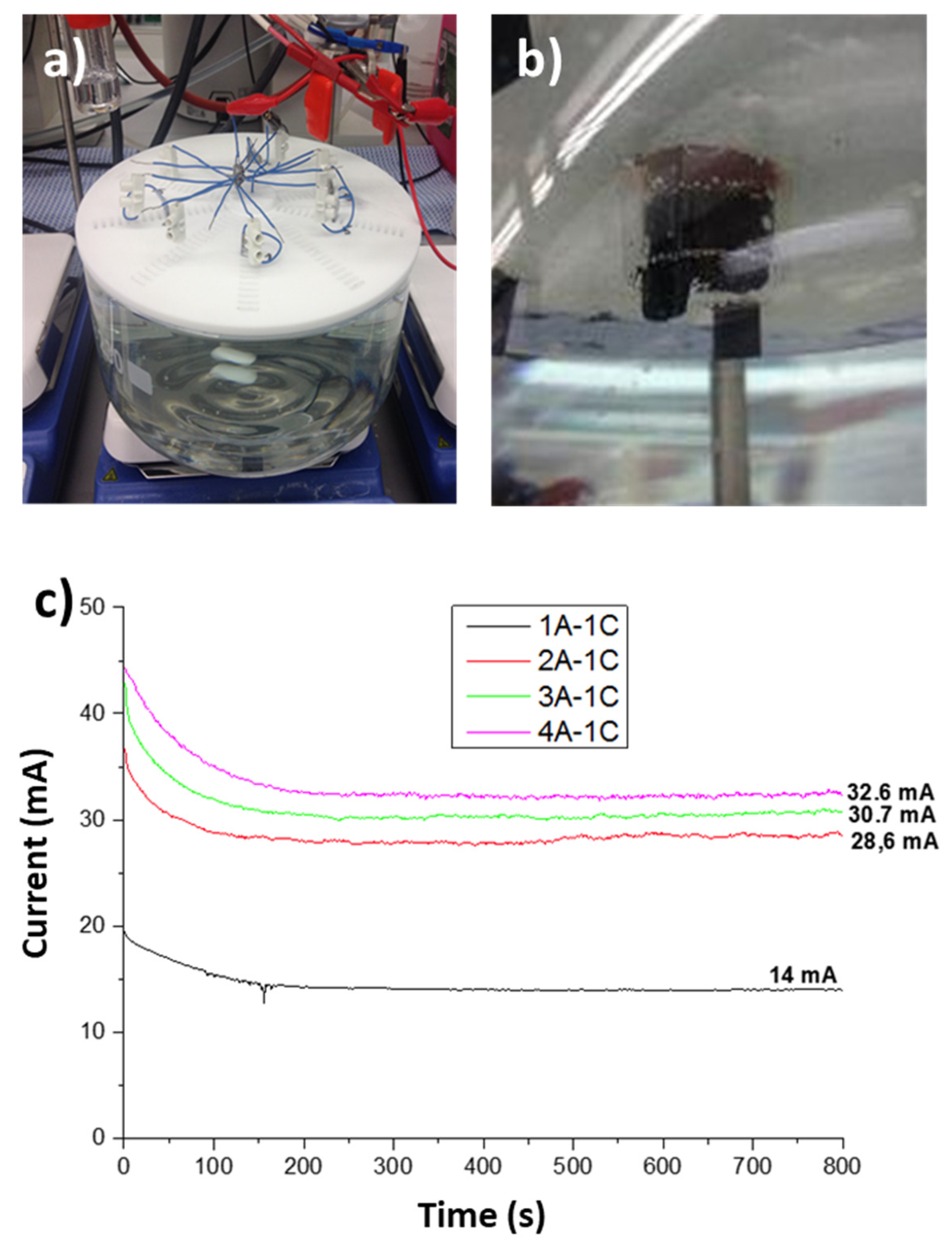
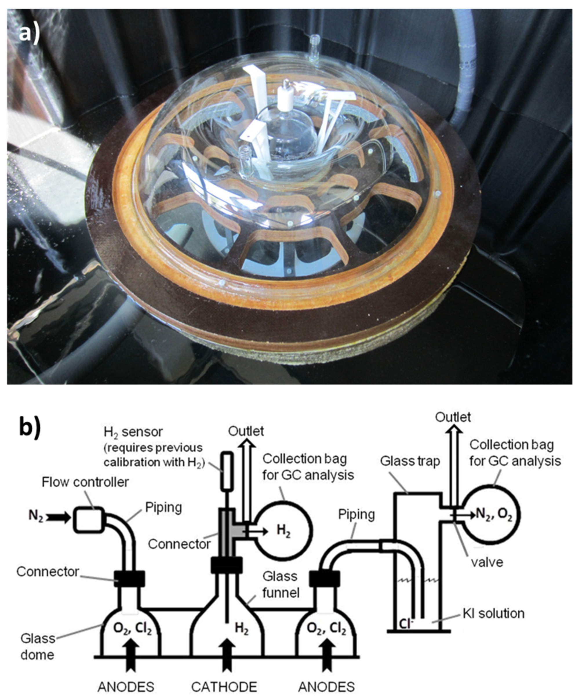
3.2. Prototype Design and Construction

We envisioned a floating device with a double dome structure to collect the products, with H2 at the cathode and O2/Cl2 at the anode (Figure 5a,b), equipped with photovoltaic cells. This architecture separates the gas effluents by gravity. A circular geometry was chosen for better symmetry and stability of the system. The cathode is located at the center of the device, below a glass funnel used as the gas collector for hydrogen. The anodes (Figure 5c) are phosphorous-doped Si wafers, coated with FTO and decorated with CoFePB nanoparticles, as described in the previous section, and are located under a second dome to collect the oxidation gases. They are radially separated from the cathode by a 10 cm distance. According to the optimum 4 cm2anode–1 cm3cathode ratio, the electrolyzer was initially dimensioned for a 1016 cm2 anode, in the form of eight wafers (two-sided, 10 cm-diameter) and 250 cm3 of dried carbon felt. However, in the final prototype design, a carbon felt volume of 150 cm3 was actually implemented (as in Figure 4), which led to an anode-to-cathode ratio (6.77) that was higher than optimal (4). The reason was to prevent cathode expansion upon wetting in an attempt to prevent the strong fibers from compacting in the main pipe of the electrolyzer and to support the hydrogen bubbles’ evolution. The sheet of carbon felt is wrapped around a central graphite rod (see Figure 5d).
Regarding anode connections, cylindrical titanium pieces (1 cm-diameter) were initially used to hold the anodes, although, due to corrosion issues noticed after preliminary tests were performed on the prototype, these connections were replaced by tin welding and all electrical connections were carefully isolated with epoxy resin, which showed good resistance under seawater oxidation conditions. The electrodes were sandwiched in a plastic frame to keep the electrical connections insulated from seawater.
Schematics of the prototype and electrode assemblies can be observed in Figure 6 and in Section S3 of the Supplementary Materials (Figures S5–S11).
To ensure and regulate flotation, a foam was placed under the dome and a sand deposit was placed at the bottom of the cathode central cylinder to allow device weight control, according to operational requirements. A full list of the materials employed for the prototype construction (Table S1), including the manufacturing technology in each case, along with the calculation of the floatability of the prototype, can be found in Section S4 of the Supplementary Materials. Pictures taken during the assembly of the different pieces can also be found in Section S5 in the SI (Figures S12–S21).

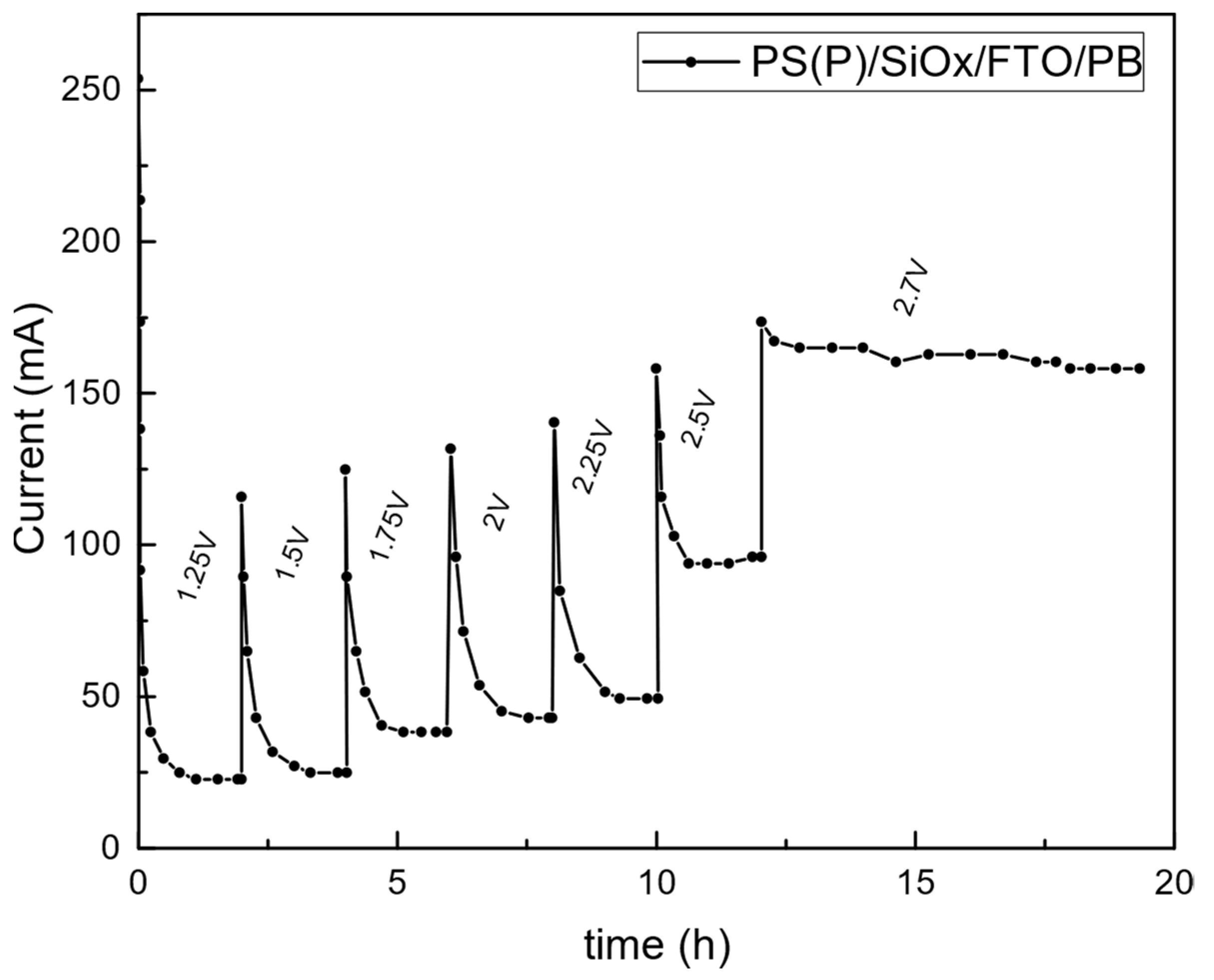
3.3. Prototype Validation

The validation stage of the seawater electrolyzer was carried out with a power supply to define the photovoltaic cells needed to drive the process. Electrochemical tests were carried out while floating on a 1000 L-tank containing 650 L seawater (Figure 7a). The H2 concentration in the cathode gas headspace was measured in situ by a H2 sensor, as schematized in Figure 7b. Simultaneously, gas effluents from both the cathode and the anode chambers were collected by gas sampling bags for ex situ analysis by gas chromatography (GC) after trapping Cl2 in a KI solution in the latter case. Next, the generated Cl was quantified by iodometric titration, as shown in a previous work [12]. A high-flow recirculation pump (5 m3 h−1) was employed in order to increase the turbulence of the medium and favour the transfer of reactants/products to/from the electrodes. More pictures of the validation scenario can be found in Section S6 in the SI (Figures S22–S24).
Chronoamperometry measurements were performed at different cell voltages (Figure 8). As previously observed at laboratory scale, the obtained currents were increased upon increasing the cell voltage up to 2.7 V. However, the stability of the system was lower than in previous tests and, more importantly, the obtained currents were much lower than expected. By using the same anode and cathode electrodes, the current density at 2.7 V decreased from 0.16 (Figure 4) to 0.08 mA cm−2 (Figure 8). This clearly suggests that there are several issues to take into account, mainly due to mass transfer limitations and electrode deactivation phenomena, as discussed below. The obtained current of 80 mA at 2.7 V is theoretically associated with a hydrogen production rate of only 0.56 mL min−1. This slow production, along with the large death volume of the funnel and the pipes and the likely loss of hydrogen bubbles out of the collection pipe, makes it difficult to quantify the hydrogen production. Still, it is important to note that, during a long chronoamperometry measurement performed at 2.7 V, the hydrogen concentration in the cathode headspace gas was successfully monitored in situ with an H2 sensor (see Section S7 in SI), and a value of around 24,000 µmol L−1 was reached, which corresponds to 54% H2 (Figure S25). This value is in good agreement with the hydrogen concentration obtained by the gas chromatography analysis of three collected samples, with an average of 60% H2 (Table S2). However, these values were significantly affected by the presence of oxygen and nitrogen, whose relative concentration values perfectly matched the air composition (Table S3). Thus, if one discards the circumstantial presence of air bubbles, which were likely introduced from the pump recycling streams, the actual H2 concentration can be recalculated as 90.13%. It should also be noted that the analysis response was very slow (delayed by several hours, as can be observed in Figure S25) due to a number of different reasons, including the low production rate, the absence of controlled carrier gas, the high headspace gas volume and, especially, the slow diffusion of the hydrogen bubbles through the carbon felt pores.
Thus, with a hydrogen faradaic efficiency of 90.13% obtained at 2.7 V, one can estimate an electrical energy efficiency of 79.7 kWh kg−1H2, or 7.2 kWh Nm−3H2. According to the average EU price of energy in the second semester of 2020, i.e., 0.1254 € kWh−1, the hydrogen production cost with the seawater electrolyzer would be around 10 € kg−1H2. Unfortunately, the quantification of oxygen and chlorine production was not accomplished, which was likely due to the low expected production rates at these current densities (even lower than in the case of H2), and to the extremely large anode headspace gas volume. Instead, the proposed analytical system in Figure 6b proved to be suitable for product analysis in seawater electrolysis tests carried out at laboratory scale [12] and it could be fully implemented in a scaled-up prototype as long as the mentioned limitations are bypassed. Furthermore, a solid precipitate was observed on the surface of both the carbon felt and the graphite rod; it was collected after the electrocatalytic tests on the prototype. An ICP-MS analysis revealed the presence of large amounts of Mg, likely in the form of Mg(OH)2 [12,27], along with Na, Ca and many other compounds (see Table S4, Section S8 in the Supplementary Materials for more details).
Regarding the coupling of a photovoltaic cell with the seawater electrolyzer, by considering the electrocatalytic results obtained to date, the authors propose to employ a commercial modular cell called ClickCell, placed on the top of the electrolyzer (Figure 9). This cell would be convenient due to its high flexibility, easy integration and installation and reduced photovoltaic cell size.
In order to choose the most suitable module among all the potential options (Figure S26), we assumed the maximum energy requirements of this seawater electrolyzer by considering the maximum current obtained with 1016 cm2 anode that would be expected based on the current density obtained at laboratory scale (1.75 mA cm−2, Figure 3). As a result, the modular configuration that best matched the energy requirements is the in-parallel connection of four modules with an open circuit voltage of 4.72 V, a short circuit current of 0.60 A and a maximum power of 2.20 W. A more detailed discussion can be found in Section S9 (Figure S26, Tables S5 and S6).

4. Discussion

After analyzing all the results obtained with the PS/SiOx/FTO/CoFe-PB anodes in the different configurations, it is clear that the electrocatalytic performance decreased, in terms of anode-area-normalized current density, over course of the scaling-up process, from 1.75 mA cm−2 at 2.7 V, with a total anodic area of only 8 cm2, through 0.16 mA cm−2 when increasing the area to 1060 cm2 (still in a low-volume device of 20 L under magnetic stirring), to 0.08 mA cm−2 when using the same anodic area in the final seawater electrolyzer prototype (650 L with recycling pump). Regarding the first loss of normalized activity, it should be noted that the anode area-to-cathode volume ratio eventually employed with a 1060 cm2 anode and a 150 cm3 cathode was slightly above the optimum ratio found at a low scale. Still, the performance loss of ten times was very pronounced. Among the different possible reasons, the most plausible is the inefficient scaling-up of the catalyst preparation in its different steps when handling higher Si wafer areas. The applied deposition method was selected for this proof-of-concept due to its simplicity, but it lacks homogeneity and controllability. In this sense, other deposition methods should be explored in the future, such as the spray deposition of catalyst-containing ink or in situ catalyst growth on the FTO surface using the hydrothermal method.
Subsequently, when switching from a laboratory-scale 20 L batch cell to the seawater electrolyzer floating on 650 L seawater, although the anode and cathode dimensions were the same, many other features that were different, such as the water volume proportion or the stirring method (magnetic stirring vs. recycling pump), which probably led to different turbulence regimes in the vicinity of the electrodes. Furthermore, even using the same electrodes, their disposal and, in the case of the cathode, compaction were also different. As a consequence, there were likely multiple mass transfer limitations caused by: (i) inefficient turbulence (i.e., stirring) at the electrode surface, which may also have led to local pH variations; (ii) intrinsic diffusion limitations of the macroporous cathode, and the consequently hindered release of the generated hydrogen bubbles, which were prone to being retained inside the carbon filaments; (iii) increased density of the carbon felt as it was compacted inside the central pipe of the electrolyzer; and (iv) the formation of solid precipitates that stacked on the cathode surface which, in turn, increased the electrode surface electrical resistance and accentuated the mass transfer limitations. These issues are also likely to have arisen in the first scaling-up process but were clearly accentuated in the final scaling-up.
Some of the enlisted issues would probably diminish when operating the electrolyzer in open water. For example, the absence of salt gradients and spontaneous water recycling in the electrode’s vicinity would surely be favorable. However, from the point of view of upgrading the current seawater electrolyzer’s performance in terms of current density and hydrogen production rate, we suggest: (i) upgrading the anode formulation and the deposition method scaling-up, in order to enhance the intrinsic catalytic activity of the anode (e.g., by lowering the onset oxidation potential) and to make the scaling-up process more homogeneous; (ii) employing significant amounts of cathode to ensure the maximum exploitation of the anodes and, in the case of materials with diffusion limitations such as carbon felt, to maximize the geometric area rather than the volume; (iii) exploring other kinds of cathode material with lower onset potential for hydrogen evolution reaction and with different textural properties favoring hydrogen release, (iv) making strong efforts towards the optimization of the media stirring procedure to maximize the turbulence at the electrode surface and to modify the structural design of the electrolyzer to favour hydrodynamics, (v) incorporating some kind of preferential channel in contact with the electrode surface along which the seawater is (somehow) forced to flow, i.e., the PEM electrolyzer microchannel concept, at a larger scale.
From the point of view of upgrading the product analysis conditions, the analysis of the different expected gaseous products, i.e., H2, O2, Cl2, was greatly hindered as another consequence of the electrocatalytic performance loss upon scaling up. In this regard, other design and construction considerations must also be considered for future prototype designs, such as (a) the decrease in the gas headspace volumes, especially in the case of the anodic compartment, which led to huge substrate dilution and delays in the analyzer response, and (b) the improvement of the mechanical isolation of the different submerged compartments of the prototype to avoid gaseous product losses, without compromising the proper stirring of the media. However, the fastest and most straightforward pathway to improve the product analysis sensitivity will surely be the improvement of the electrocatalytic performance of the electrolyzer. The higher the obtained currents (and thus, the higher the production rates), the higher the efficiency and accuracy of all the analytical methods, and the faster their response.
The quantification of O2 and Cl2 was not accomplished in the present study but, in a recent publication by this group on water oxidation using FTO/CoFe-PB electrodes [12], the quantitative production of different anodic species, i.e., oxygen, chlorine, hypochlorous acid and hypochlorite, depending on the applied potential, was confirmed. The reaction was almost quantitative towards oxygen evolution reaction (OER) at low potentials and the O2/Cl2 ratio decreased as the potential was increased. On the other hand, chlorine species began to form from 2.4 V and chlorine gas became the major oxidation product at cell voltages above 3 V. This trend can be attributed to the fact that the chloride oxidation reaction (Reaction 1) requires fewer electrons than the water oxidation reaction (Reaction 2). Hence, although the latter presents lower thermodynamic potential, the chlorine production is kinetically favored. This point must be taken into consideration in future research on seawater electrooxidation, since not only hydrogen, but also chlorine may be selectively obtained as a value-added product by tuning the catalyst and the operation conditions. Indeed, chlorine production is of significant interest from a commercial point of view due to the strong impact of the chloro-alkali industry.
2Cl → Cl2 + 2e;              E0 = 1.36 V vs. NHE
2H2O → O2 + 4H+ + 4e;  E0 = 1.23 V vs. NHE
In the case of hydrogen, we did achieve some quantitative measurements in the present work and, low-productivity considerations aside, the faradaic efficiency value obtained for the HER (Reaction 3), i.e., 90.15%, is noteworthy. Apart from the mechanical losses of the hydrogen bubbles, the missing 9.85% hydrogen may have been due to side reactions taking place at the cathode, as also suggested by the presence of precipitates.
2H+ + 2e → H2;           E0 = 0 V vs. NHE
The electric energy cost of hydrogen generation in any kind of electrolyzer ultimately depends on the applied cell voltage. Thus, with the proposed seawater electrolyzer operating at 2.7 V, the associated hydrogen energy cost is 79.7 kWh kg−1H2 while, for example, in the case of alkaline water electrolyzers operating at an average voltage of 1.8 V, the hydrogen energy cost is 48.2 kWh kh−1H2. The higher energy requirement in the present case would be compensated, in any case, by using renewable energy sources such as solar energy, as also pointed out in the present project, with a hypothetical solar-to-hydrogen efficiency above 7%, as long as the aforementioned operational and scaling-up issues are resolved.

5. Conclusions

We designed and constructed an autonomous, solar-powered electrolyzer able to produce hydrogen while floating on seawater. This exercise demonstrates that sea water electrolysis can be carried out with non-critical raw materials and low-cost fabrication methods. The simplicity of our approach certainly adds real data to the ongoing discussion on the benefits of direct sea water electrolysis. We achieved a production rate of >0.5 mL H2 per minute with a rudimentary device, built in our laboratories, and a hydrogen faradaic efficiency of >90% was quantified. Our catalyst was robust when working in extremely harsh conditions to obtain hydrogen and chlorine, both gases of industrial interest. On the other hand, there is much room for engineering improvement that must be re-thought for future designs. After overcoming the operational and scaling-up issues discussed herein, without any further improvement at the catalytic level, the seawater electrolyzer coupled with a standard photovoltaic cell could reach solar-to-hydrogen efficiencies higher than 7%.

Supplementary Materials

The following are available online at https://www.mdpi.com/article/10.3390/w14030453/s1. Figure S1: (a) TEM image and (b) dynamic light scattering (DLS) obtained from CoFe-PB nanoparticles. Figure S2: SEM images obtained from (a–d) PS(P)/SiOx/FTO/PB and (e–h) PS(Sb)/SiOx/FTO/PB anodes after the different synthesis steps: (a,e) formation of porous silicon (PS) by anodization of n-type silicon wafers doped with P or Sb; (b,f) passivation of PS; (c,g) deposition of flurorine-doped tin oxide (FTO) by spray pyrolysis; and (d,h) deposition of cobalt iron Prussian blue (CoFe-PB) nanoparticles by dip coating. Figure S3: (a) SEM image obtained from carbon felt cathode and (b) linear sweep voltammetry of carbon felt cathode (used as working electrode) in seawater after different pretreatment conditions: (i) untreated, (ii) immersed in 1 M H2SO4 solution for 5 h, (iii) heated at 450 °C in air overnight and (iv) combination of ii and iii. Pt mesh was used as anode (counter electrode). Figure S4: Linear sweep voltammetry of PS(P)/SiOx/FTO/CoFe-PB anode in seawater using Pt mesh (1 cm × 1 cm) or carbon felt (1 cm × 1 cm × 1 cm) as cathode. Figure S5: final design of the seawater electrolysis system. Top left: assembly. Right: exploded view. Bottom left: subassemblies list. Figure S6: Detail of the flotation body subassembly. Top: assembly. Middle: exploded view. Bottom: parts list. Figure S7: detail of the main pipe subassembly. Top left: assembly. Right: exploded view. Bottom left: parts list. Figure S8: detail of the anodes support subassembly. Top: exploded view. Bottom, parts list. Figure S9: detail of the anodes subassembly. Left: assembly. Right: exploded view. Bottom: parts list. Figure S10: detail of the cathode subassembly. Left: assembly. Right: exploded view. Bottom: parts list. Figure S11: detail of the table subassembly. Top: assembly. Middle: exploded view. Bottom: parts list. Figure S12: main structure of the seawater electrolyzer system. Figure S13: detail of the collection chambers of the gases: dome and funnel. Figure S14: top view of the assembly of the seawater electrolyzer system. Figure S15: detail of the cathode and anodes supports and the ballast. Figure S16: flotability ring assembly on the seawater electrolyzer system. Figure S17: detail of the floatability ring assembled on the seawater electrolyzer system. Figure S18: assembly of the anodes on the seawater electrolyzer system. Figure S19: detail of the anodes assembled on the seawater electrolyzer system. Figure S20: view of the support, connections and housing. Figure S21: detail of the connections and housing. Figure S22: seawater electrolyzer prototype on the tank used for the testing stage. Figure S23: hydrolyzer auxiliary devices on the prototype validation scenario. Figure S24: connections for the gases and electric source on the seawater electrolyzer system. Figure S25: (a) chronoamperometry measurement at 2.7 V with the seawater electrolyzer system, using PS/SiOx/FTO/CoFe-PB (1016 cm2) and C-felt (150 cm3); (b) in situ measurement of hydrogen concentration in the cathode gas headspace with H2 sensor. Figure S26: (a) power curves and (b) technical specifications of ClickCell modules. Figure S27: design of the printed circuit board (PCB) for the voltage regulator. Table S1: bill of materials. Table S2: gas chromatography analysis of the cathode gas headspace at 15,000 s in the test in Figure S25. Table S3: comparison of relative O2 and N2 concentration in the cathode gas headspace compared with air. Table S4: elemental analysis by ICP-MS on precipitate sample scratched from carbon felt and graphite rod after all chronoamperometry measurements performed in the seawater electrolyzer system. Table S5: power specifications of the ClickCell modules. Table S6: technical specifications of the required power regulator.

Author Contributions

Conceptualization, M.G.-A., J.G.-C., F.A.G.-P. and J.R.G.-M.; methodology, B.R.-G., M.T., Ò.A.-A., M.A., D.G., J.G.-C., F.A.G.-P.; investigation, B.R.-G., M.T., Ò.A.-A., M.G.-A., D.G., J.G.-C. and F.A.G.-P.; writing—original draft preparation, J.R.G.-M., J.G.-C., F.A.G.-P., B.R.-G., M.T., Ò.A.-A., M.A. and D.G.; writing—review and editing, J.R.G.-M., J.G.-C. and F.A.G.-P.; supervision, J.G.-C., F.A.G.-P. and J.R.G.-M.; project administration, D.G.-T. and J.R.G.-M.; funding acquisition, J.R.G.-M. All authors have read and agreed to the published version of the manuscript.

Funding

This research was funded by The European Union through ERC-PoC grant HYDRER (ID 664719) and ERC StG grant CHEMCOMP (ID 279313); the Ministerio de Ciencia e Innovación through Severo Ochoa Excellence Accreditation 2020-2023 (ID CEX2019-000925-S, MIC/AEI); the FEDER/Ministerio de Ciencia e Innovación, Agencia Estatal de Investigación (project RTI2018-095618-B-I00); the Generalitat de Catalunya (ID 2017-SGR-1406), and the CERCA Program/Generalitat de Catalunya.

Data Availability Statement

The data presented in this study are available on request from the corresponding authors. The data are not publicly available due to privacy.

Conflicts of Interest

The authors declare no conflict of interest.

References

  1. El-Dessouky, H.T.; Ettouney, H.M. Fundamentals of Salt Water Desalination; Elsevier: Amsterdam, The Netherlands, 2002. [Google Scholar]
  2. Global Issues. Water. 2018. Available online: https://www.un.org/en/global-issues/water (accessed on 4 December 2021).
  3. Hausmann, J.N.; Schlögl, R.; Menezes, P.W.; Driess, M. Is direct seawater splitting economically meaningful? Energy Environ. Sci. 2021, 14, 3679–3685. [Google Scholar] [CrossRef]
  4. Farràs, P.; Strasser, P.; Cowan, A.J. Water electrolysis: Direct from the sea or not to be? Joule 2021, 5, 1921–1923. [Google Scholar] [CrossRef]
  5. O’Brien, T.F.; Bommaraju, T.V.; Hine, F. Handbook of Chlor-Alkali Technology; Springer: New York, NY, USA, 2005; Volume 1. [Google Scholar]
  6. Bennett, J. Electrodes for generation of hydrogen and oxygen from seawater. Int. J. Hydrog. Energy 1980, 5, 401–408. [Google Scholar] [CrossRef]
  7. Kato, Z.; Sato, M.; Sasaki, Y.; Izumiya, K.; Kumagai, N.; Hashimoto, K. Electrochemical characterization of degradation of oxygen evolution anode for seawater electrolysis. Electrochim. Acta 2014, 116, 152–157. [Google Scholar] [CrossRef]
  8. Surendranath, Y.; Dincǎ, M.; Nocera, D.G. Electrolyte-Dependent Electrosynthesis and Activity of Cobalt-Based Water Oxidation Catalysts. J. Am. Chem. Soc. 2009, 131, 2615–2620. [Google Scholar] [CrossRef]
  9. Dionigi, F.; Reier, T.; Pawolek, Z.; Gliech, M.; Strasser, P. Design Criteria, Operating Conditions, and Nickel–Iron Hydroxide Catalyst Materials for Selective Seawater Electrolysis. ChemSusChem 2016, 9, 962–972. [Google Scholar]
  10. Ros, C.; Murcia-López, S.; Garcia, X.; Rosado, M.; Arbiol, J.; Llorca, J.; Morante, J.R. Facing seawater splitting challenges by regeneration with Ni–Mo–Fe bifunctional electrocatalyst for hydrogen and oxygen evolution. ChemSuschem 2021, 14, 2872–2881. [Google Scholar] [CrossRef]
  11. Hsu, S.; Miao, J.; Zhang, L.; Gao, J.; Wang, H.; Tao, H.; Hung, S.; Vasileff, A.; Qiao, S.Z.; Liu, B. An earth-abundant catalyst-based seawater photoelectrolysis system with 7.9% solar-to-hydrogen efficiency. Adv. Mater. 2018, 30, 1707261. [Google Scholar] [CrossRef]
  12. Hegner, F.S.; Garcés-Pineda, F.A.; González-Cobos, J.; Rodríguez-García, B.; Torrens, M.; Palomares, E.; López, N.; Galan-Mascaros, J.R. Understanding the catalytic selectivity of cobalt hexacyanoferrate toward oxygen evolution in seawater electrolysis. ACS Catal. 2021, 11, 13140–13148. [Google Scholar] [CrossRef]
  13. Pintado, S.; Goberna-Ferrón, S.; Escudero-Adán, E.C.; Galan-Mascaros, J.R. Fast and Persistent Electrocatalytic Water Oxidation by Co–Fe Prussian Blue Coordination Polymers. J. Am. Chem. Soc. 2013, 135, 13270–13273. [Google Scholar] [CrossRef]
  14. Alsaç, P.; Ülker, E.; Nune, S.V.K.; Dede, Y.; Karadas, F. Tuning the Electronic Properties of Prussian Blue Analogues for Efficient Water Oxidation Electrocatalysis: Experimental and Computational Studies. Chem. Eur. J. 2018, 24, 4856–4863. [Google Scholar] [CrossRef] [PubMed]
  15. Han, L.; Tang, P.; Reyes-Carmona, A.; Rodríguez-García, B.; Torréns, M.; Morante, J.R.; Arbiol, J.; Galan-Mascaros, J.R. Enhanced activity and acid pH stability of Prussian blue-type oxygen evolution electrocatalysts processed by chemical etching. J. Am. Chem. Soc. 2016, 138, 16037–16045. [Google Scholar] [CrossRef] [PubMed] [Green Version]
  16. Vo, V.; Van, M.N.; Lee, H.I.; Kim, J.M.; Kim, Y.; Kim, S.J. A new route for obtaining Prussian blue nanoparticles. Mater. Chem. Phys. 2008, 107, 6–8. [Google Scholar] [CrossRef]
  17. Goberna-Ferrón, S.; Hernandez, W.Y.; Rodríguez-García, B.; Galán-Mascarós, J.R. Light-driven water oxidation with metal hexacyanometallate heterogeneous catalysts. ACS Catal. 2014, 4, 1637–1641. [Google Scholar] [CrossRef]
  18. Lehmann, V.; Gösele, U. Porous silicon formation: A quantum wire effect. Appl. Phys. Lett. 1991, 58, 856–858. [Google Scholar] [CrossRef]
  19. Garcés-Pineda, F.A.; González-Cobos, J.; Torrens, M.; Galan-Mascarós, J.R. Fluorine-doped tin oxide/alumina as long-term robust conducting support for earth-abundant water oxidation electrocatalysts. ChemElectroChem 2019, 6, 2282–2289. [Google Scholar] [CrossRef] [Green Version]
  20. Garcés, F.; Budini, N.; Arce, R.; Schmidt, J. Effect of thickness on structural and electrical properties of Al-doped ZnO films. Thin Solid Film. 2015, 574, 162–168. [Google Scholar] [CrossRef]
  21. OSHA. Method ID-126SGX, Chlorine and Chlorine Dioxide in Workplace Atmosphere. 2007. Available online: http://niosh.dnacih.com/nioshdbs/oshameth/t-id126sgx-pv-01-0112-m/t-id126sgx-pv-01-0112-m.html (accessed on 4 December 2021).
  22. Cheng, F.; Feng, X.; Chen, X.; Lin, W.; Rong, J.; Yang, W. Synergistic action of Co-Fe layered double hydroxide electrocatalyst and multiple ions of sea salt for efficient seawater oxidation at near-neutral pH. Electrochim. Acta 2017, 251, 336–343. [Google Scholar] [CrossRef]
  23. Izumiya, K.; Akiyama, E.; Habazaki, H.; Kumagai, N.; Kawashima, A.; Hashimoto, K. Anodically deposited manganese oxide and manganese-tungsten oxide electrodes for oxygen evolution from seawater. Electrochim. Acta 1998, 43, 3303–3312. [Google Scholar] [CrossRef]
  24. Cotillas, S.; Llanos, J.; Rodrigo, M.A.; Cañizares, P. Use of carbon felt cathodes for the electrochemical reclamation of urban treated wastewaters. Appl. Catal. B Environ. 2015, 162, 252–259. [Google Scholar] [CrossRef]
  25. Biswal, M.; Deshpande, A.; Kelkar, S.; Ogale, S. Water electrolysis with a conducting carbon cloth: Subthreshold hydrogen generation and superthreshold carbon quantum dot formation. ChemSusChem 2014, 7, 883–889. [Google Scholar] [CrossRef] [PubMed]
  26. Kim, K.J.; Kim, Y.-J.; Kim, J.-H.; Park, M.-S. The effects of surface modification on carbon felt electrodes for use in vanadium redox flow batteries. Mat. Chem. Phys. 2011, 131, 547–553. [Google Scholar] [CrossRef]
  27. Tong, W.; Forster, M.; Dionigi, F.; Dresp, S.; Erami, R.S.; Strasser, P.; Cowan, A.J.; Farràs, P. Electrolysis of low-grade and saline surface water. Nat. Energy 2020, 5, 367–377. [Google Scholar] [CrossRef]
Figure 1. ESEM images obtained from (a) PS(P)/SiOx/FTO/CoFe-PB and (b) PS(Sb)/SiOx/FTO/CoFe-PB.
Water 14 00453 g001
Figure 2. Seawater electrooxidation (pH ≈ 8) in three-electrode configuration. (a) Linear sweep voltammetry of PS/SiOx/FTO/CoFe-PB (red lines) and PS/SiOx/FTO (black lines) electrodes (4 cm2 geometric area in each case) with optimized deposition protocol (solid line doped with phosphorus and dotted line doped with Sb). (b) Chronoamperometry at 1.65 V vs. Ag/AgCl with the catalysts prepared on silicon doped with phosphorus (red) and antimony (black). Cathode: Pt mesh.
Water 14 00453 g002
Figure 3. (a,b) Pictures of the two-electrode configuration cell used for optimization of the anode-to-cathode ratio (anode: PS(P)/SiOx/FTO/CoFe-PB, cathode: carbon felt). (c) Chronoamperometry at 2.7 V cell voltage in seawater with different anode-to-cathode ratios. The caption refers to the anode/cathode electrode proportion, but anodes are in all cases deposited on both sides. Thus, 4 cm3 cathode (dried) and x cm2 anode (x = 8, 16, 24, 32) were tested.
Water 14 00453 g003
Figure 4. Chronoamperometry measurements at different cell voltages performed in the first scaling-up process, in a 20 L batch cell using PS/SiOx/FTO/CoFe-PB (1016 cm2) and C-felt (150 cm3).
Water 14 00453 g004
Figure 5. Concept design of (a,b) the solar seawater electrolyzer, (c) anode and (d) cathode.
Water 14 00453 g005
Figure 6. Schemes of (a) anode and (b) cathode assemblies, (c) Scheme and (d) pictures of the electrolyzer prototype.
Water 14 00453 g006
Figure 7. (a) Seawater electrolyzer device on the tank used for the evaluation stage. (b) Scheme of set-up proposed for simultaneous collection of all gases prior to analysis.
Water 14 00453 g007
Figure 8. Chronoamperometry measurements at different cell voltages performed in the seawater electrolyzer system, using PS/SiOx/FTO/CoFe-PB (1016 cm2) and C-felt (150 cm3).
Water 14 00453 g008
Figure 9. (a) Assembly of ClickCell modular cell on the seawater electrolyzer. (b,c) Schematics of a single ClickCell and four modules connected in parallel (16.6 cm × 16.6 cm). Source: NOUSOL.
Water 14 00453 g009
Publisher’s Note: MDPI stays neutral with regard to jurisdictional claims in published maps and institutional affiliations.

