
An Alternative Method to Develop Embroidery Textile Strain Sensors


Departament of Electronic Engineering, Universitat Politecnica de Catalunya, ESEIAAT, Colom 1, 08222 Terrasa, Spain
*
Author to whom correspondence should be addressed.
Textiles 2021, 1(3), 504-512; https://doi.org/10.3390/textiles1030026
Submission received: 21 September 2021
/
Revised: 8 November 2021
/
Accepted: 10 November 2021
/
Published: 13 November 2021
(This article belongs to the Special Issue Fibrous Materials (Textiles) for Functional Applications)
Abstract
:In this paper, a method to develop embroidered textile strain resistive sensors is presented. The method is based on two overlapped zigzag conductive yarn patterns embroidered in an elastic textile. To demonstrate the functionality of the proposed configuration, a textile sensor embroidered with a conductor yarn composed of 99% pure silver-plated nylon yarn 140/17 dtex has been experimentally characterised for an elongation range from 0% to 65%. In order to show the sensor applicability, a second test with the sensor embroidered in a knee-pad has been done to evaluate the flexion knee angle from 180° to 300°. The experimental results show the usefulness of the proposed method to develop fabric strain sensors that can help to manufacture commercial applications on the healthcare sector.
1. Introduction
At present, smart-textiles are being used in more and more applications everyday [1]. Researchers are more conscious than before about the possibilities that smart-textiles can provide to develop new wearable sensors to improve our way of life [2]. Wearable sensors can be used as a core to develop different applications such as health monitoring [3,4], physical training and recover [5], emergency and security services and law enforcement [6]. This research field is growing and increasing its interest due to the improvement in the performance and new functionalities that they provide [7]. In this sense, textile substrates could be the perfect choice to develop wearable electronic applications. The main reason is the fact that humans have been covering their body with them. The integration of wearable sensors on these textiles could be done in multiple ways by using several techniques such as ink-jet printing [8], screen printing, electrospinning [9], dip coating [10], embroidery [11,12] or the introduction of conductive yarns into weaving process [13].
Among these methodologies, embroidery presents an optimal balance, due to the availability of the manufacturing technology, the efficient operation of the expensive conductive threads and the possibility of massive repeatability of geometries and layouts [14]. Since the embroidery method provides a fast prototyping process, it has been revealed as the most cost-effective technique to implement wearable sensors and it has been chosen for this work.
Strain sensors are starting to be present in health applications [15] as one of the most suitable fields of application [16]. Physical recovery has been revealed as one of the most interesting applications for these sorts of sensors, and more specifically, movement recovery. In fact, the strain sensor could provide information about the movement. Is the movement done properly? Is the force spent enough to ensure that the muscle is recovered? Questions like these could be answered using strain sensors integrated in clothes or fabrics that should be worn by the patient.
The resistive strain sensors have been typically developed by means of a conductive polymeric yarns [17,18]. The necessity of elastic implementation implies that standard conductive yarns are usually discarded. However, in this work, an alternative method to use a standard conductive yarn to develop resistive strain sensor is presented. The usefulness of the proposed alternative method is experimentally demonstrated at both the device level and application level, by means of the characterisation and integration of the sensor on a knee-pad to measure the knee flexion angle, respectively.
The remainder of the paper is organised as follows. Section 2 describes the material and methods used, including the conductive yarn, the textile substrates and its implementation as well as the measurement set-up. In Section 3, the experimental results are shown and discussed. Finally, in Section 4, the conclusions are summarised.
2. Materials and Methods
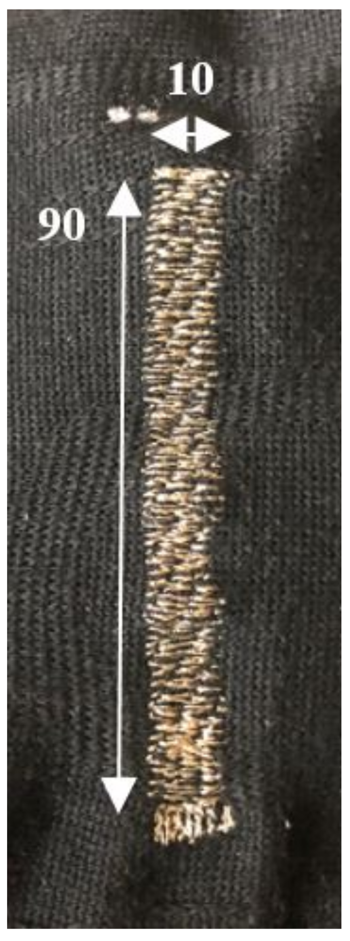
The proposed resistive strain sensor is based on a crossed zig-zag embroidered structure whose dimensions are depicted in Figure 1. To embroider the sensor, two different yarns were chosen. The conductive yarn is a commercial Shieldex 117/17 2-ply, made by polyamide with a 99% pure silver coating. Shieldex yarn was produced by the coating of polyamide filaments, which were join onto groups of seventeen filaments. Two of these groups of seventeen filaments are joined with torsion. As a result, a conductive yarn is obtained with a linear resistance lower than . The support yarn is a polyester multifilament yarn without torsion. Furthermore, this substrate is slightly elastic with a composition of polyester 80% and elastodiene 20%.
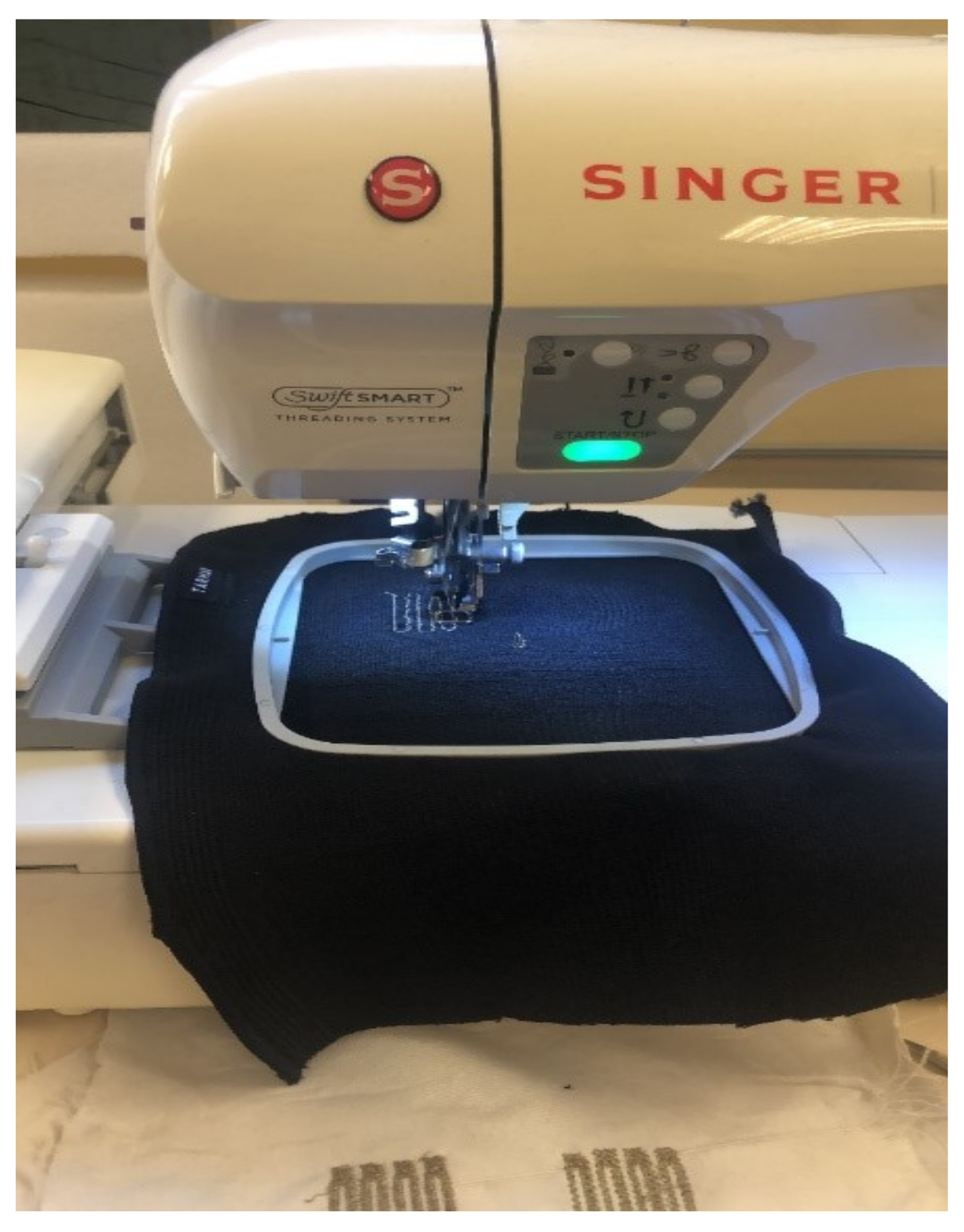
To embroider the sensor pattern in the elastic substrate, a Singer Futura XL-550 embroidery machine is used. In order to embroider on an elastic substrate, a non-conventional set up is prepared. The standard needle was changed for a thinner one, which had a width of 0.7 mm, the embroidery speed was decreased to the minimum, which is 90 spm (stitches per minute) and the tension of the yarn was selected to adapt to a suitable value. In order to avoid embroidery mechanical problems, the substrate was attached on the holder without an external tension, Figure 2.
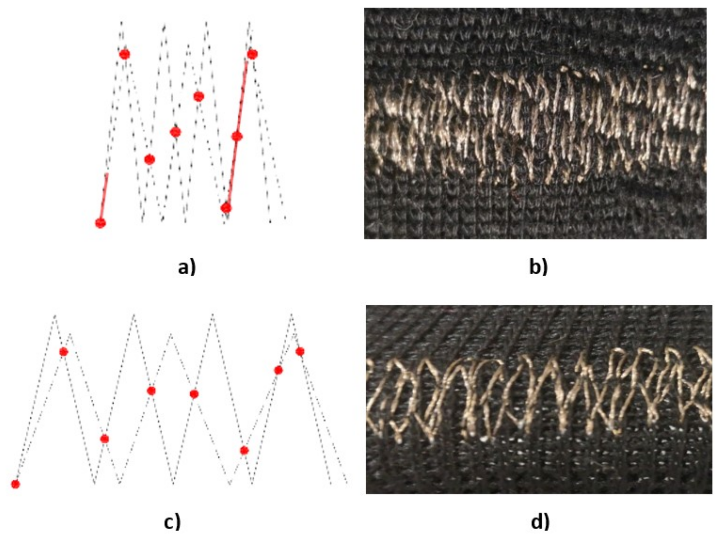
In order to choose the embroidery pattern, after a few tests, it was observed that normal patterns that the embroidery machine can work with could not reach the required mechanical parameters. In fact, the yarn is not elastic, then it was required to develop a new pattern whose mechanical behaviour was modified when the fabric was stretched. In order to do that, different patterns were tested to achieve a dynamic pattern allowing movement when stretching. Figure 3 shows the proposed pattern. It consists of two zigzag embroidered patterns overlapped with a different stitch density and height, which corresponds to a density ratio of 1.33 between them and a height ratio of 0.7. For the same length the number of stitches for zigzag in A is 1.33 higher than zigzag B. With this ratio, eight contact zones are defined between both patterns for each cycle (dot in Figure 3).
The overall resistance is determined by the equivalent parallel resistance sections between both zigzag structures mainly defined by the contact points and contact zones. When the structure is stretched the relative distance of contact points increases and thus, the effective length of the sensor increases. Therefore, the sensor resistance is increased, as is shown on Figure 3b.
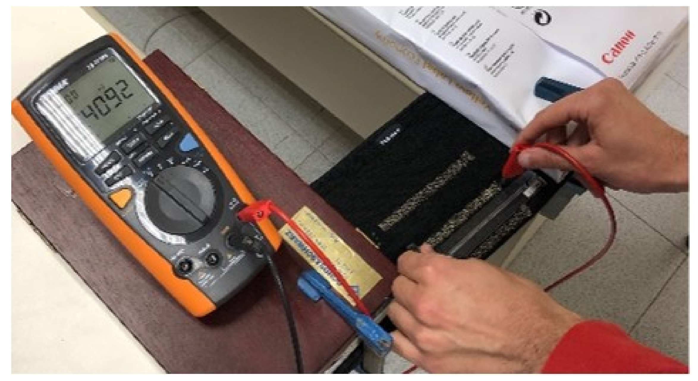
Figure 4 show the strain sensor characterisation setup. The textile sensor was attached between 2 supports. The distance between both supports was increased in steps of 0.5 cm until the sensor reaches an increase of 65% in length, (maximum limit that the fabric can be stretched), and then it was decreased also in steps of 0.5 cm until to return to the initial state. This process was made 3 times in a row, with no rest time. The corresponding array of sensor resistances was measured with a multimeter Tenma 72-7730A with an accuracy of ±0.4 + 20 Ω.
In order to check the repeatability, three cycles were done for every sensor and threes sample manufactured on the same fabric were characterised.
To evaluate the sensor resistance shift () with the elongation (), Equations (1) and (2) were used, respectively. Equation (3) was used to evaluate the elastic constant (k) of the measured sensor
where and denote the resistance and sensor length without stress, and and denote the resistance and sensor length under strain conditions, respectively.
The impact of a washing cycle on the electrical sensor performance was also evaluated. To properly do the washing cycle a standard requirement were follow, which are defined on the UNE-EN ISO 6330:2012. The regulation defines a series of soaps and washing machines. For the case under study a neutral ECE-Color Detergent ISO 105-C06 soap (Testgewebe Gmbh, Brüggen, Germany) was used in a Balay T5609 (BSH Electrodomesticos, Zaragoza, Spain) washing machine. The washing cycle test was performed with 1 kg of support textile, 1% by weight of soap (i.e., 10 g) and the washing machine was configured at 40 °C and 1000 rpm. Once the sensor fabrics were washed the sensor resistance characterisation was repeated.
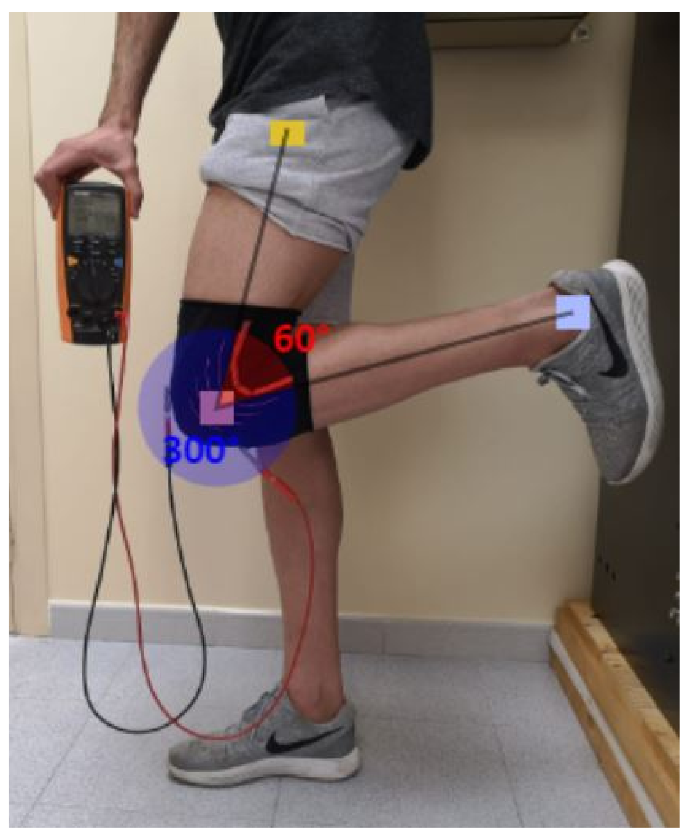
Finally, in order to evaluate the feasibility of the proposed embroidery method to develop wearable sensor in a real healthcare situation, the knee flexion angle was used as a figure of merit for patients to evaluate their physical recovery treatments. In our experiment, the sensor was embroidered in a knee-pad and the resistance versus knee angle was evaluated. Since the position of the sensor was one of the key aspects of the system, the sensor was embroidered on the front part of the knee-pad to obtain the information about knee flexion angle without having interference on the movement of the patient. To measure the resistance values of the sensor two snap probes were located on the edges. The snaps have a resistance of 0.6 mΩ, which was evaluated to prevent the effect on the measurements. For each knee flexion the sensor resistance was measured and a photograph was taken with a distance between camera and knee of 1.5 m. The distance was selected to obtain the best picture to measure the angle of the knee without any deformation. The flexion angle of the knee was obtained from an image analyser ergonomic software from Universitat Politecnica de Valéncia [19]. as it is shown in Figure 5. The knee was bent from 180° (no flexion) to 300°.
3. Results and Discussion
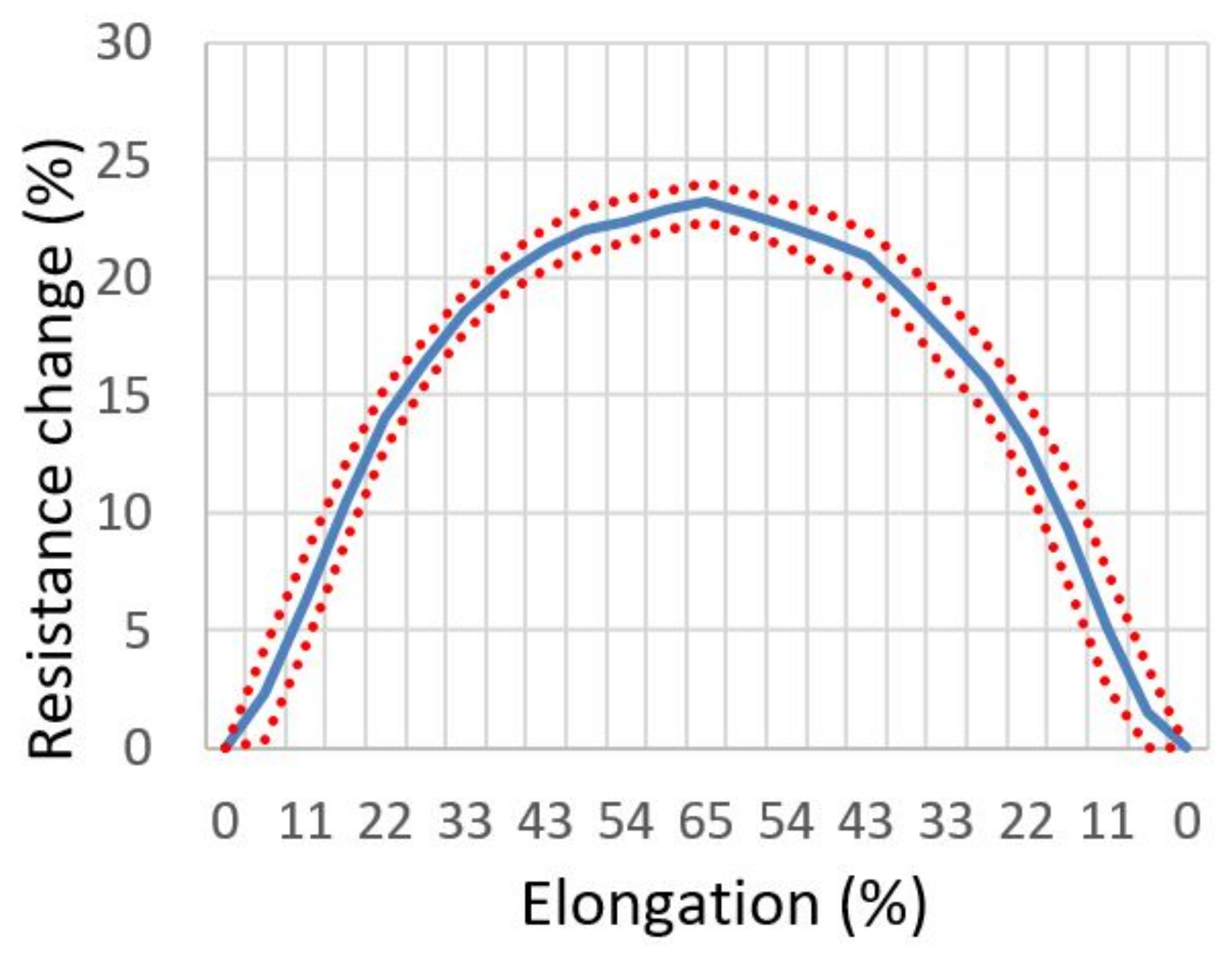
Figure 6 shows the mean measured sensor resistance and dispersion when a swept strain cycle up and down from 0% to 65% of elongation is applied. It is shown how the resistance variation is dependent on the amount of strain that the fabric suffers, and how it recovers after it arrives to the maximum distance. The developed sensor shows a nonlinear behaviour. Two clear tendencies can be observed. Up to 40% of elongation, the resistance shift represents an increase of 20%. However, from 40% to 65% of elongations the resistance shift only increases from 20% to 23%. This sensitivity curve points out that a good linear behaviour and high sensitivity can be obtained when the sensor elongations is lower than 40%. In this zone the sensor works properly and provides a suitable behaviour to be used. Above 40%, the pattern starts to not being affected by the stretching of the substrates, this is due to the differences of the contacts positions are so low than the resistance value is not changing according to the increase of length.
If the strain up and down behaviours are compared, both show a similar resistance shift against elongation which denotes the full recovery of the sensor after applying stress without any significant value of hysteresis. The values of hysteresis observed trough the test was lower than 1%. The graph presents also the repeatability which is referred to the standard deviation of the different sensors. The maximum standard deviation arrives to the value of ±2% for lower strain value, for higher strain value the deviation is reduced up to ± 1% or less. It is observed that the low deviation results in stability between cycles and different samples. The deviation observed could be explained by the differences on the pattern embroidered or the continuity of the yarn, which can modify the distribution of contact points along the sensor.
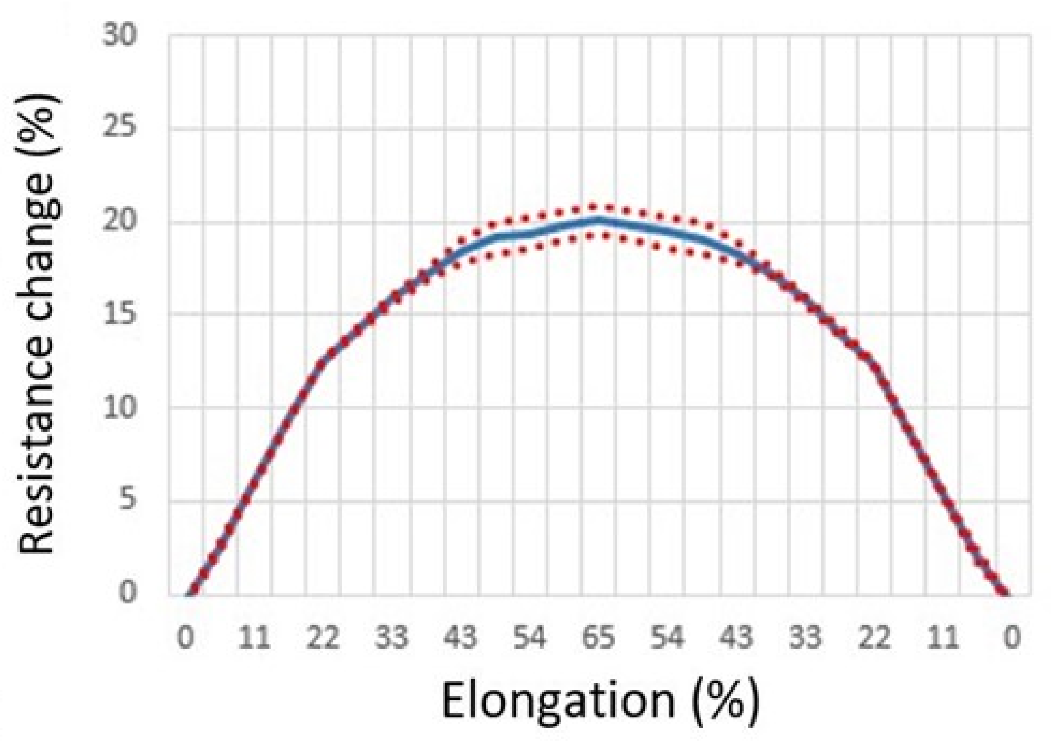
Once the sensors where characterised, the fabric sensors were washing according to the procedure detailed on the previous section. Figure 7 shows the sensor resistance behaviours after the washing cycle. Slight differences are observed on sensor behaviour after a washing cycle. From previous works [20], it was observed that after the first washing cycle, the reduction of electrical properties suffered by sensors is lower than the first cycle. For this reason, only one washing cycle was done. The sensor sensitivity decreases after washing cycle from 24% of resistance variation before washing to 20% after washing when 65% of strain is applied. Another important fact that could be emphasised is the variation on repeatability. It is reduced for elongation up to 30% and it is not reaching the 1% of deviation. However, for higher elongation states the impact of washing on deviation is nor increasing or decreasing the error values, significantly. The variation changes from a maximum of 1% to a value of 0.86% before and after washing, respectively. In any case, although washing, the sensor does not lose its functionality and the behaviour remains constant up to 40% elongation, pointing out the useful zone for the sensor functionality.
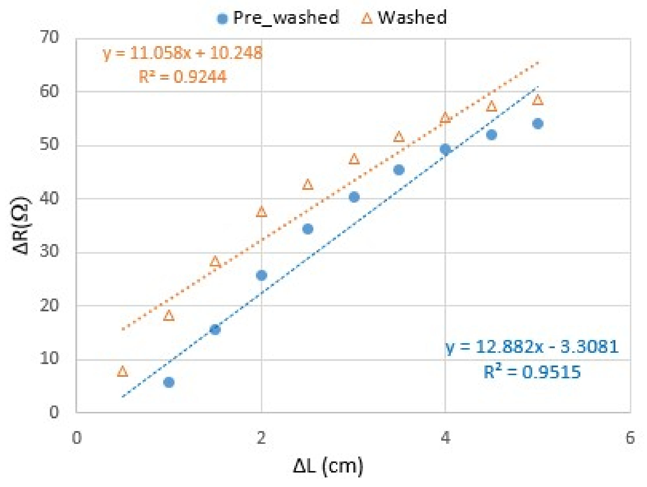
On Figure 8 the evaluation of elongation constant (k) was done following the Equation (3). For the pre-washed samples (dash blue regression), it is obtained k = 12.9 Ω/cm meanwhile for the washed samples (dot orange regression) it is obtained k = 11.1 Ω/cm. On the case of the measured elastic constant the change experimented is about 14.1%. This change is due to the decrease of sensibility that the sensor suffers after washing cycle, the resistance variation values are reduced and they have an effect on elastic constant value.
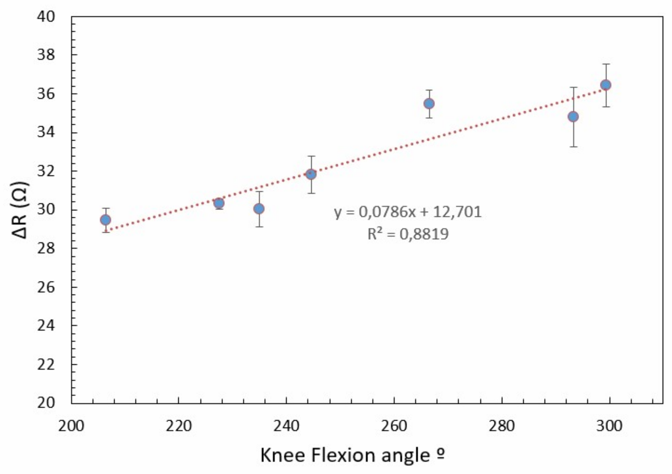
To test the functionality of the proposed sensor on healthcare applications, the sensor was embroidered on a knee-pad to measure the sensor resistance against knee flexion angle following the procedure details on previous section (Figure 5). Figure 9 shows the resistance shift with the different knee flexion angle. When the leg is in rest position 180° (not flexion), the resistance corresponds to 210 Ω, the sensor is in its initial position and this value is used as a reference value to quantified the resistance variation. After the legs starts to flex, the strain increases the distance of electrical contact between both zigzag patterns, increasing the effective length and therefore the resistance. The resistance increases with a sensitivity of 78.6 mΩ/° with a regression coefficient of 0.88, the obtained results demonstrated experimentally the functionally of the proposed embroidered method to develop wearable sensor for healthcare applications. Moreover, a higher linearity if high-end embroidered machine should be used.
4. Conclusions
In this work, an alternative embroidered method to develop textile strains sensors has been proposed and characterised. The proposed textile sensor has been characterised before and after washing. The results show that the sensor resistive can measure up to 65% of elongation, which corresponds to the maximum elongation of elastic substrate. Moreover, up to 40% of elongation the sensor resistance behaviour is linear and no hysteresis effect on up and down strain cycle is observed. The washing cycle slightly reduces the sensitivity but the device functionality remains.
A knee-pad with the proposed embroidered sensor was developed to evaluate the knee flexion angle on patients. A clear dependence of sensor resistance with knee flexion angle was observed. Despite the fact that the sensor behaviour should be improved to develop a commercial application, these preliminary results reveal the usefulness of the proposed embroidered method to develop healthcare applications and opens a new research line to improve sensor’s performance to achieve a commercial product that can help to evaluate and quantify the patient recovery medical treatment. Future test should be prepared by health professionals to use the proposed sensor in a patients’ treatment where the recovery of the movement of the knee must be monitored.
5. Patents
T P201930793, Universitat Politécnica de Catalunya, Sensor resistivo de elongación.
Author Contributions
Conceptualization, M.M.-E. and R.F.-G.; methodology, M.M.-E.; formal analysis, M.M.-E. and R.F.-G.; investigation, M.M.-E.; writing—original draft preparation, M.M.-E. and R.F.-G.; writing—review and editing, I.G.; supervision, I.G. and R.F.-G. All authors have read and agreed to the published version of the manuscript.
Funding
This work was supported by Spanish Government-MINECO under Project TEC2016-79465-R and AGAUR-UPC(2020 FI-B 00028).
Institutional Review Board Statement
Not applicable.
Informed Consent Statement
Not applicable.
Acknowledgments
The author’s thanks Ivan Ruperez to take the measurement shows in this paper.
Conflicts of Interest
The authors declare no conflict of interest.
References
- Wilson, S.; Laing, R. Fabrics and garments as sensors: A research update. Sensors 2019, 19, 3570. [Google Scholar] [CrossRef] [PubMed] [Green Version]
- Yang, K.; Isaia, B.; Brown, L.J.E. E-Textiles for Healthy Ageing. Sensors 2019, 19, 4463. [Google Scholar] [CrossRef] [PubMed] [Green Version]
- Xie, R.; Du, Q.; Zou, B.; Chen, Y.; Zhang, K.; Liu, Y.; Liang, J.; Zheng, B.; Li, S.; Zhang, W.; et al. Wearable Leather-Based Electronics for Respiration Monitoring. ACS Appl. Bio Mater. 2019, 2, 1427–1431. [Google Scholar] [CrossRef]
- He, W.; Wang, C.; Wang, H.; Jian, M.; Lu, W.; Liang, X.; Zhang, X.; Yang, F.; Zhang, Y. Integrated textile sensor patch for real-time and multiplex sweat analysis. Sci. Adv. 2019, 5, eaax0649. [Google Scholar] [CrossRef] [PubMed] [Green Version]
- Wu, J.F.; Qiu, C.; Wang, Y.; Zhao, R.; Cai, Z.P.; Zhao, X.G.; He, S.S.; Wang, F.; Wang, Q.; Li, J.Q. Human Limb Motion Detection with Novel Flexible Capacitive Angle Sensor Based on Conductive Textile. Electronics 2018, 7, 192. [Google Scholar] [CrossRef] [Green Version]
- Ma, Z.; Xu, R.; Wang, W.; Yu, D. A wearable, anti-bacterial strain sensor prepared by silver plated cotton/spandex blended fabric for human motion monitoring. Colloids Surf. A Physicochem. Eng. Asp. 2019, 582, 123918. [Google Scholar] [CrossRef]
- Schwarz, A.; Langenhove, L.V.; Guermonprez, P.; Deguillemont, D. A roadmap on smart textiles. Text. Prog. 2010, 42, 99–180. [Google Scholar] [CrossRef]
- Salim, A.; Lim, S. Review of recent inkjet-printed capacitive tactile sensors. Sensors 2017, 17, 2593. [Google Scholar] [CrossRef] [PubMed] [Green Version]
- Xue, J.; Wu, T.; Dai, Y.; Xia, Y. Electrospinning and electrospun nanofibers: Methods, materials, and applications. Chem. Rev. 2019, 119, 5298–5415. [Google Scholar] [CrossRef]
- Smith, R.E.; Totti, S.; Velliou, E.; Campagnolo, P.; Hingley-Wilson, S.M.; Ward, N.I.; Varcoe, J.R.; Crean, C. Development of a novel highly conductive and flexible cotton yarn for wearable pH sensor technology. Sens. Actuators B Chem. 2019, 287, 338–345. [Google Scholar] [CrossRef]
- Martinez-Estrada, M.; Moradi, B.; Fernández-Garcia, R.; Gil, I. Impact of manufacturing variability and washing on embroidery textile sensors. Sensors 2018, 18, 3824. [Google Scholar] [CrossRef] [PubMed] [Green Version]
- Soukup, R.; Hamacek, A.; Mracek, L.; Reboun, J. Textile based temperature and humidity sensor elements for healthcare applications. In Proceedings of the 2014 37th International Spring Seminar on Electronics Technology, Dresden, Germany, 7–11 May 2014; pp. 407–411. [Google Scholar] [CrossRef]
- Ou, J.; Oran, D.; Haddad, D.D.; Paradiso, J.; Ishii, H. SensorKnit: Architecting Textile Sensors with Machine Knitting. 3D Print. Addit. Manuf. 2019, 6, 1–11. [Google Scholar] [CrossRef] [Green Version]
- Grethe, T.; Borczyk, S.; Plenkmann, K.; Normann, M.; Rabe, M.; Schwarz-Pfeiffer, A. Textile humidity sensors. In Proceedings of the Symposium on Design, Test, Integration and Packaging of MEMS/MOEMS (DTIP 2018), Rome, Italy, 22–25 May 2018; pp. 1–3. [Google Scholar] [CrossRef]
- Carnevale, A.; Longo, U.G.; Schena, E.; Massaroni, C.; Lo Presti, D.; Berton, A.; Candela, V.; Denaro, V. Wearable systems for shoulder kinematics assessment: A systematic review. BMC Musculoskelet. Disord. 2019, 20, 546. [Google Scholar] [CrossRef] [PubMed]
- Morris, H.; Murray, R. Medical textiles. Text. Prog. 2020, 52, 1–127. [Google Scholar] [CrossRef]
- Golgouneh, A.; Tahmidul Islam Molla, M.; Dunne, L.E. A comparative feasibility analysis for sensing swelling with textile-based soft strain sensors. In Proceedings—International Symposium on Wearable Computers, ISWC; Association for Computing Machinery: London, UK, 2019; pp. 60–65. [Google Scholar] [CrossRef]
- Eutionnat-Diffo, P.A.; Chen, Y.; Guan, J.; Cayla, A.; Campagne, C.; Zeng, X.; Nierstrasz, V. Stress, strain and deformation of poly-lactic acid filament deposited onto polyethylene terephthalate woven fabric through 3D printing process. Sci. Rep. 2019, 9, 1–18. [Google Scholar] [CrossRef]
- ERGONAUTAS. Ruler—Univeristat Politecnica de Valencia. 2006. Available online: https://www.ergonautas.upv.es/herramientas/ruler/ruler.php (accessed on 23 April 2020).
- Martínez-Estrada, M.; Moradi, B.; Fernández-Garcia, R.; Gil, I. Impact of conductive yarns on an embroidery textile moisture sensor. Sensors 2019, 19, 1004. [Google Scholar] [CrossRef] [PubMed] [Green Version]
Figure 1.
Layout of the embroidered sensor (dimensions in mm).

Figure 2.
Embroidered sensor manufacturing.

Figure 3.
Details of zigzag A (continuous line) and zigzag B (dash line) embroidered pattern. Red dots or lines represent the electrical contact points or contact zones between both zigzag pattern (a) pattern without strain (low resistance) (b) real image of the pattern without strain (c) pattern under strain conditions (high resistance as result of an increase of the effective length) (d) real image of the pattern under strain conditions.

Figure 4.
Strain sensor characterisation setup.

Figure 5.
Characterisation of Knee flexion versus sensor resistance on kneepad.

Figure 6.
Measured resistance variation at different strain points. Up and down strain cycle and repeatability (dot line) are represented.
Figure 6.
Measured resistance variation at different strain points. Up and down strain cycle and repeatability (dot line) are represented.

Figure 7.
Measured resistance variation at different strain points after a washing cycle. Up and down strain cycle and repeatability (dot line) are represented.
Figure 7.
Measured resistance variation at different strain points after a washing cycle. Up and down strain cycle and repeatability (dot line) are represented.

Figure 8.
Elastic constant measurement before and after washing.

Figure 9.
Measured resistance for different knee angles.

Publisher’s Note: MDPI stays neutral with regard to jurisdictional claims in published maps and institutional affiliations. |
© 2021 by the authors. Licensee MDPI, Basel, Switzerland. This article is an open access article distributed under the terms and conditions of the Creative Commons Attribution (CC BY) license (https://creativecommons.org/licenses/by/4.0/).
Share and Cite
MDPI and ACS Style
Martínez-Estrada, M.; Gil, I.; Fernández-García, R. An Alternative Method to Develop Embroidery Textile Strain Sensors. Textiles 2021, 1, 504-512. https://doi.org/10.3390/textiles1030026
AMA Style
Martínez-Estrada M, Gil I, Fernández-García R. An Alternative Method to Develop Embroidery Textile Strain Sensors. Textiles. 2021; 1(3):504-512. https://doi.org/10.3390/textiles1030026
Chicago/Turabian StyleMartínez-Estrada, Marc, Ignacio Gil, and Raúl Fernández-García. 2021. "An Alternative Method to Develop Embroidery Textile Strain Sensors" Textiles 1, no. 3: 504-512. https://doi.org/10.3390/textiles1030026