
Shearing Deformations of β-Cristobalite-Like Boron Arsenate
by
 , , and
James N. Grima-Cornish
1 ,
,
Liana Vella-Żarb
2 ,
,
Krzysztof W. Wojciechowski
3,4 and
Joseph N. Grima
1,2,*
1
Metamaterials Unit and Faculty of Science, University of Malta, MSD 2060 Msida, Malta
2
Department of Chemistry, Faculty of Science, University of Malta, MSD 2060 Msida, Malta
3
Institute of Molecular Physics, Polish Academy of Sciences, Smoluchowskiego 17/19, 60-179 Poznan, Poland
4
Akademia Kaliska im. Prezydenta Stanisława Wojciechowskiego, Nowy Swiat 4, 62-800 Kalisz, Poland
*
Author to whom correspondence should be addressed.
Symmetry 2021, 13(6), 977; https://doi.org/10.3390/sym13060977
Submission received: 26 April 2021
/
Revised: 14 May 2021
/
Accepted: 19 May 2021
/
Published: 31 May 2021
(This article belongs to the Special Issue Metamaterials and Symmetry)
Abstract
:Boron arsenate, BAsO4, is crystalline material ( group) that was recently shown to be auxetic in its (001) plane for loading in any direction in this plane, and, which exhibits negative linear compressibility at elevated pressured in its [001] direction. This work presents and discusses the results of extensive density functional theory (DFT) based simulations aimed at studying deformations that such crystals undergo when subjected to shear loading in an attempt to obtain a better insight into the manner in which this material responds to mechanical loads. The deformations for shearing in the (001) plane are described in terms of the ‘rotating squares’ model, which was used to explain the auxeticity in the same plane where it was shown that shear loading results primarily in deformations which make the ‘squares’ become ‘parallelogram-like’ rather than rotate. This lack of rigidity in projected ‘squares’ was discussed by looking at changes in bond lengths and bond angles.
1. Introduction
Boron arsenate, BAsO4, see Figure 1, is a spectacular material having both a history and a prehistory, particularly in terms of its synthesis and crystal properties. Prior to being characterised and noted as a material with its own importance by Schulze in the early 1930s [1,2,3], it was first mentioned by Berger in a note published a century ago which presented a number of novel reactions [4]. In one of Berger’s new reactions, arsenic was obtained by evaporation of the resultant compound formed of the mixture of arsenic acids and boric acids. Here, boron arsenate was not characterized and no particulars were given for the synthesis of the compound, as it was not the scope of their study, in which it was used as a reducible compound to form arsenic vapours. This crystal was then first characterized using X-Ray diffraction by Schulze in 1933 [1], when it was described as consisting of connected tetrahedra of BO4 and AsO4, which is the structural model being used in this work.
Schulze’s method for the synthesis of the crystal, was described in a later publication the following year as a solid state reaction between arsenic oxide (As2O5) and boron trioxide (B2O3) at high temperature [2]. This method produced fine single crystals with edges of approximately 0.1 mm in length. Within the same publication, Schulze reported that the crystal was tetragonal, a result which was inferred from the tetragonal growth of the crystals. This 1934 publication also made the first comparison of BAsO4 to the structure of cristobalite, a report which led to a number of important advances throughout the years. According to Gruner [5], another article published at around this time was by Levi and Ghiron [6], where it was determined that the boron arsenate that grows from such crystallizations is in one crystalline form, i.e., it is isomorphic.
Another two methods for preparing boron arsenate were described within the same year (1934), one by Schumb and Hartford [7] and the other by Gruner [5]. In the former, 100 g of arsenic acid (H3AsO4) were dissolved in the minimum amount of water before any solid suspended matter was filtered off. The filtered solution was then heated to its boiling point and 20 g of boric acid (B(OH)3) were added. The solution was kept at boiling point until a white precipitate formed. This white precipitate contained small crystals which were examined and characterized in a conglomerate form. The specifics on the size of the crystals and the characterization carried out were actually reported by Schulze in 1935 [3], citing a private communication he had with Schumb and Hartford. The method for the preparation of BAsO4 described by Schumb and Hartford appears to be the same method which was only briefly described by Berger back in 1920 [4], and it gives important details which were not previously disclosed, thus making this synthesis reproducible.
The second method for the preparation of boron arsenate was reported by Gruner, and it involved the reaction between arsenic pentoxide and boronic acid [5]. The resulting arsenic salt product was placed in water and studied further. It was found that the boron arsenate produced, once placed in water, forms two different hydrate complexes depending on the temperature: the trihydrate (BAsO4·3 H2O) and the hexahydrate (BAsO4·6 H2O) forms. The solid forms of these two complexes have different X-ray diffraction patterns (obtained in Debye–Scherrer geometry). Both also differ from the X-ray diffraction pattern of the anhydrous form of boron arsenate [2]. Comparison with the diffraction data for corresponding boron phosphates showed a very high similarity between the powder patterns (both hydrates and anhydrates) [5]. An analysis of the literature of time, also reveals that in some of the early publications, BAsO4 was referred to as having a low-cristobalite-like structure by Schulze and later by Nieuwenkamp and also by Shafer, which is now known to not be the case; however, they correctly noted the similarity between this structure and the structure of cristobalite in general [2,8,9].
Much more recently, a microwave synthesis version of the method by Schulze was carried out successfully by Baykal et al. (2006), which decreased both the energy and the time required to carry out such a synthesis [10].
This paper will look at a different aspect in BAsO4 namely, from the perspective of its mechanical properties and will focus on the atomic level deformations that occur when this material, as a single crystal, is subjected to mechanical loads. Such a perspective is important in view of the anomalous negative Poisson’s ratio (auxetic) [11,12] and negative linear compressibility characteristics [12,13], properties it shares with a number of other anomalous materials, models and structures. In this respect it is important to highlight that both fields of auxetics and that of negative linear compressibility has grown substantially in the past few years, as discussed elsewhere [14,15,16]. For example, in the case of auxetics, apart from the very early and fundamental modelling of cellular solids [17,18], studies include production and/or experimental characterisation of polymeric auxetics [19,20] foams or other cellular systems [21,22,23], biomaterials [24], modelling and/or experimental characterisation of crystalline materials such as hydrophthalates [25] silicates [26] and other oxides [11,12,27], the developments include deign and optimisation of molecular-level auxetics [28,29,30,31,32,33], studying of various auxetic model structures and macromodels [34,35,36,37,38,39,40,41,42,43,44,45,46] including smart tuneable auxetics [47,48]. Reported applications of auxetics include sport [49], filtration [50,51], textiles [44] and medicine [52,53]. Similar advances have also been made in the field of negative compressibility [16,32,54,55,56,57,58,59,60], including a fundamental study that looks into stability aspects of such negative systems [61]. Crystal symmetry plays an important role on the manifestation or otherwise of auxetic behaviour and a number of key studies have focused on looking at crystalline materials with specific symmetries [62]. Worth highlighting are the studies on crystals with cubic symmetry [63,64,65,66] and tetragonal symmetry [67,68], to where BAsO4 belongs. The theoretical framework required to study crystals in this manner is well established and explained in detail elsewhere [69].
2. Rationale
BAsO4, see Figure 1, has a particularly interesting crystalline structure with the ‘rotating squares’ motif, well known for its auxetic characteristics [37], being projected in its (001) plane (see Figure 1b). It is hence not surprising that a number of recent studies have looked at this material to study its mechanical properties. In particular, one should mention a seminal study by Haines et al. [13] that has looked at this material as this is subjected to hydrostatic pressure. This work was able to identify, for the first time, that BAsO4 exhibits negative linear compressibility (NLC) in its [001] direction at elevated pressures. This anomalous NLC property has been explained this effect in terms of deformation of the tetrahedra which appear to be the main cause of this effect [12] (the ‘demi wine-rack mechanism’), rather than the more conspicuous tetrahedral tilting about a local axis parallel to the [001] direction. A more recent study, which looked at uniaxial loading with a focus on the [001] direction, has further confirmed this amenable mode of deformation thus re-enforcing this explanation [27].
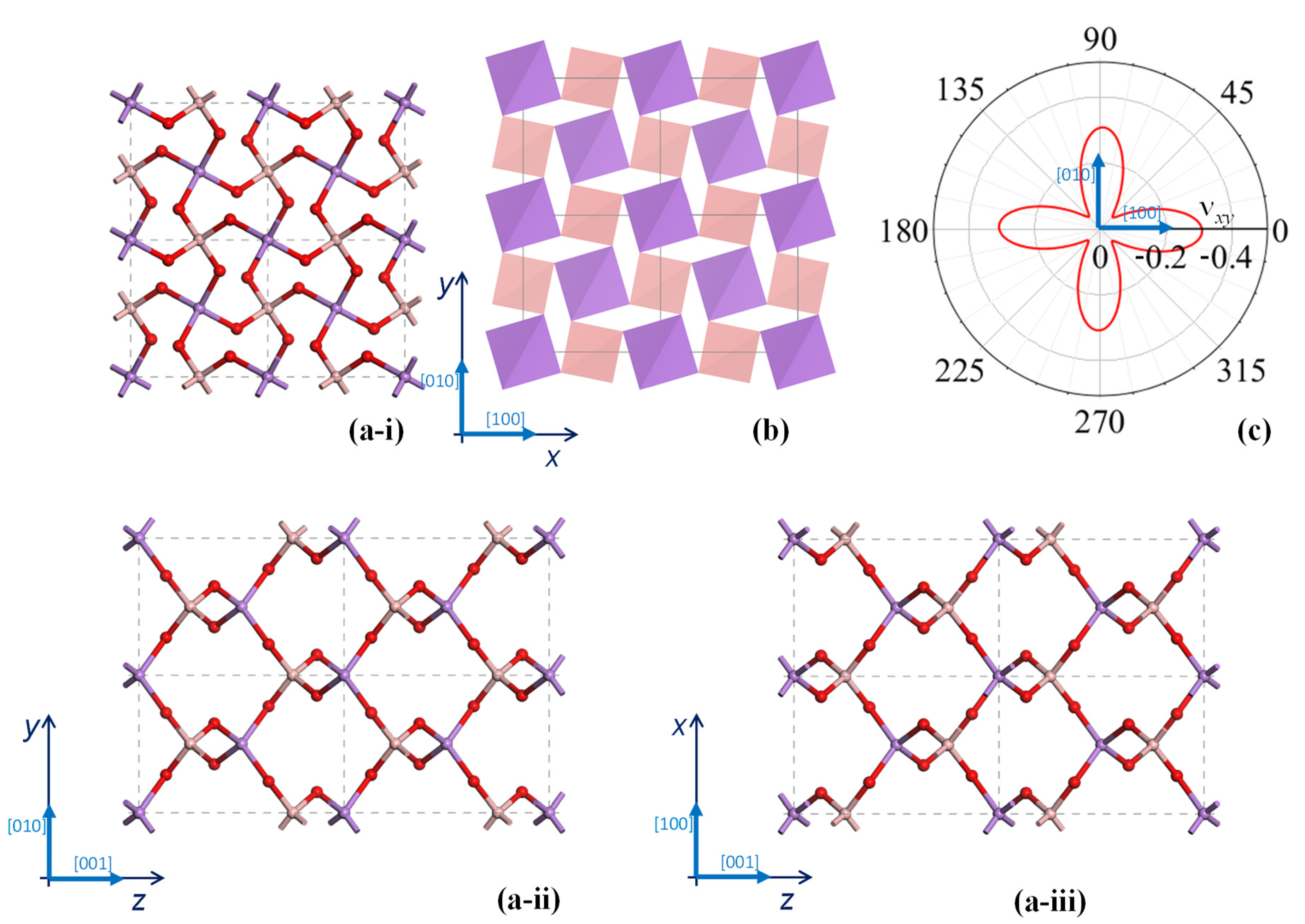
In addition to the experimentally measured NLC, BAsO4 has also been shown to exhibit a negative Poisson’s ratio in the (001) plane [11,12], see Figure 1c, a property which was explained in terms of tetrahedral rotations about a local axis parallel to the orthogonal [001] direction. More specifically, as shown in Figure 1, the tetrahedra project in the auxetic (001) plane with a ‘rotating squares’ motif [37], a geometry which is amenable to auxeticity. More importantly, a DFT based study was able to confirm that uniaxial loading in the [100] or [010] direction is predicted to result in molecular-level deformations where these 2D projected squares appear to rotate relative to each other, i.e., deform with an auxeticity inducing deformation mechanism. Here, it should be noted that as discussed by Lisovenko et al. [67,68], in general, a tetragonal crystal such as BAsO4 having a seven-constant tetragonal anisotropy (i.e., s16 = −s26 ≠ 0, see Table 1) is expected to manifest some asymmetric aspects in the dependence of the Poisson’s ratio with the direction of loading compared to its six-constant tetragonal anisotropy counterpart (i.e., s16 = −s26 = 0). This is hardly visible in Figure 1c due to the fact that the magnitude of the coefficient s16 = −s26 is too small relative to the other coefficients to induce appreciable asymmetry in the xy-plane. Obviously, asymmetry is not precluded in the other planes.
However, despite these important discoveries, there are various aspects in the mechanical behaviour BAsO4 that deserve further studies. For example, the idealised ‘rotating squares’ model, where the squares are perfectly rigid and simply rotate relative to each other [37], assumes that the system cannot shear in plane. This is the equivalent of having the compliance term s66 = 0, which would correspond to an infinite shear modulus Gxy. (Prima facie, one might ask if zero value of s66 is not in conflict with the stability of the system, which is typically granted by positive definiteness of the (Gibbs free) energy. The latter, inter alia, implies s66 > 0. The rotating square model, however, is so internally constrained that it is only a ‘one degree of freedom’ model. Thus, since shear cannot be realised in the idealised ‘rotating squares’ model, the positivity of s66 is not implementable—nor necessary.) However, as evident from Table 1, which lists the simulated compliances of BAsO4, this is not the case with s66 being predicted as 24.7 × 10⁻¹² Pa−1, corresponding to a finite Gxy = s66−1 = 40.5GPa. Furthermore, although the idealised ‘rotating squares’ model predicts a constant in-plane Poisson’s ratio of −1 irrespective of the direction of loading, the negative Poisson’s ratio in the (001) plane of BAsO4 is anisotropic and much lower in magnitude. In fact, although the DFT simulations suggest that single crystalline BAsO4 is predicted to exhibit negative Poisson’s ratio in its (100) plane for loading in any direction (see Figure 1c), the Poisson’s ratio reached a maximum negative value of just c. −0.33 on-axis with auxeticity being at a minimum at 45° off-axis.
To explain such profile of mechanical properties, it is important to not only look at the behaviour of the material when it is subjected to uniaxial loading, but also when it is subjected to shear, something which so far has never been considered in detail in the case of BAsO4. In view of this, the present paper, with the help of results from simulation, will analyse the shear properties of boron arsenate with a special focus on the nanoscale molecular-level deformations in an attempt to explain better the trends in the anomalous Poisson’s ratio of this material.
3. Simulations and Analysis
The procedure used for the simulation is based on density functional theory (DFT) approach performed using the CASTEP code [70] as implemented within the Materials Studio V6.1 modelling environment (Accelrys, now Biova, 2019). Details of the simulations are provided elsewhere [12,27]. In particular, since this study will focus on shear deformations, meaning that the unit cell will not retain its 90° unit cell angles, due importance is to be given to the manner how the crystal is aligned in the 3D global space. For this work, the single crystal of boron arsenate with its standard symmetry reduced to P1 was aligned within the global coordinate system according to the convention adopted by the Institute of Radio Engineers (IRE) [71], i.e., in a manner that the [001] crystal direction is parallel to the global z-axis and the [010] crystal direction is aligned in the global yz-plane with no constraints being placed on the [100] direction. For this type of orientation, the unit cell has its shape defined by the triangular matrix H such that:
where are the unit cell vectors which, for this type of orientation, are of the form [72]:
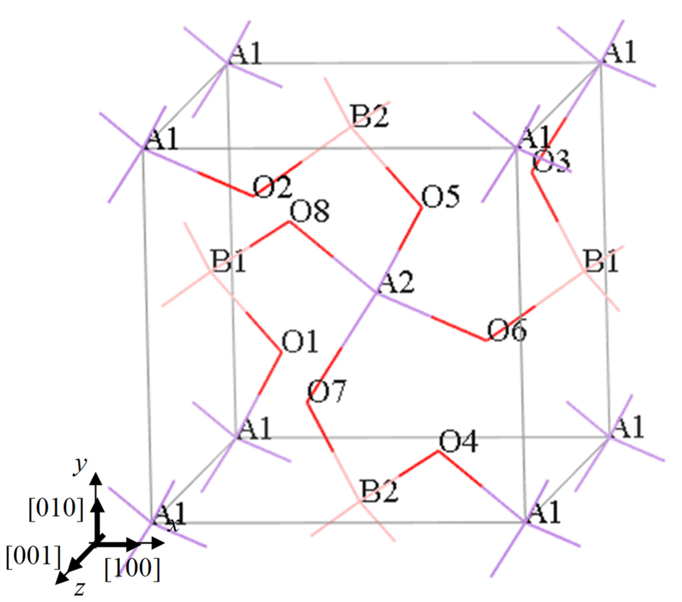
where are the unit cell lengths whilst are the unit cell angles. Here, it should be noted that the reduction of symmetry from the standard symmetry (which can be described in terms of just three independent atoms, as reported by Schulze in 1934 [2]) reduced to P1 results in a system with twelve independent atoms: two boron atoms, labelled B1 and B2; two arsenic atoms, labelled A1 and A2; and eight oxygen atoms, labelled O1, O2,…, O8) as detailed in Figure 2 and Table 2.
All density functional theory (DFT) simulations were carried out with full periodic boundary conditions being applied using the Generalised Gradient Approximation with the Perdew–Burke–Ernzerhof exchange-correlation functional (GGA–PBE) [73,74] utilising a Monkhorst–Pack Grid of 6 × 6 × 4 (k-point separation was set to approximately 0.04 Å−1). The overall charge and initial spin were set to zero. An energy cut-off value of 1200 eV was used. A geometry optimization was first carried out using the Broyden–Fletcher–Goldfarb–Shanno (BFGS) minimiser with no external pressure p being applied where the convergence criteria utilised included an energy cut off per atom of 5 × 10⁻⁶ eV atom−1 and a maximum stress on the crystal of 0.01 GPa. During the geometry optimisation process, the unit cell was being periodically realigned to the IRE default alignment [71] with no constraints on the atoms or crystal lattice being imposed, apart from those enforced through the periodic boundary conditions. Additional simulations were then performed with the system being subjected to shear stresses in the range of −10 GPa to +10 GPa using the same settings. These simulations were performed with the load being applied in an incremental manner in steps of 2GPa. These simulations compliment other simulations meant to study the behaviour of the system when subjected to uniaxial on-axis loading and a hydrostatic pressure p reported elsewhere [12,27]. Note that throughout the simulations, particularly at larger strains, care was taken to monitor the symmetry of the system, so as to ascertain, for example, that the system did not undergo a phase transition.
For all systems subjected to an external stress , the Lagrangian strains were calculated from the unit cell matrix at a stress relative to , the unit cell matrix system prior to any application of external stresses, using the procedure outlined by Schlenker et al. [72]. More specifically, the Lagrangian strain tensor for an applied stress was obtained through:
where I3 is a 3 × 3 identity matrix and is the strain tensor. The on-axis uniaxial strains in the x, y and z directions and the shear strains in the ij plane were then calculated as:
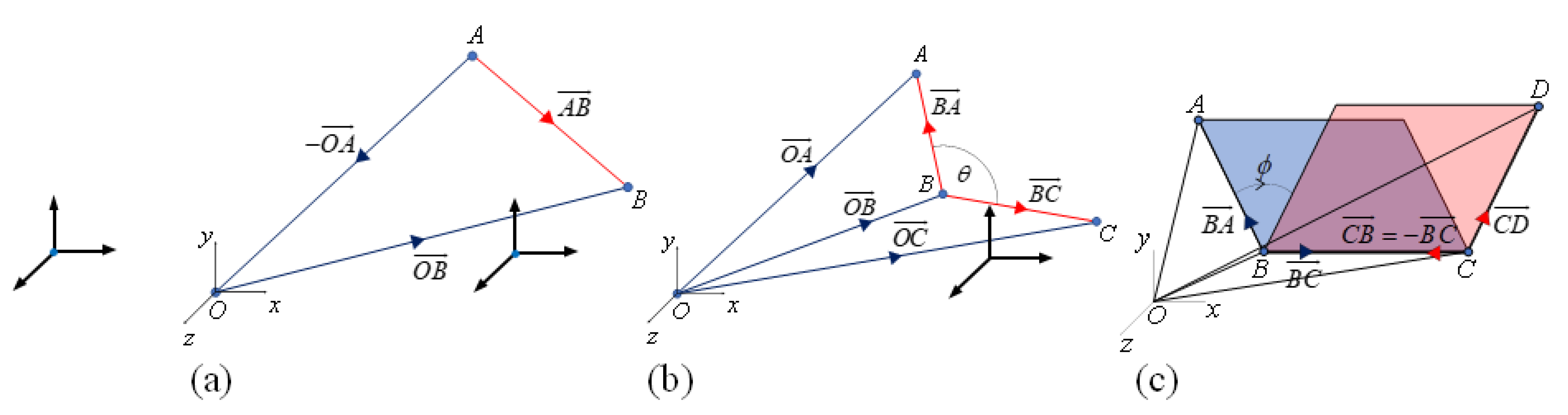
Furthermore, in order to understand the way the crystal structure changes upon the application of a mechanical loads, a number of lengths and angles between atoms in both the three-dimensional space (i.e., bond lengths, length of sides of tetrahedra, bond angles, tetrahedral angles, angles between tetrahedra, torsion angles) and the two-dimensional projection in the xy-plane (i.e., lengths of ‘projected squares’, inter- and intra-square angles) were determined using vector algebra (see Figure 3).
More specifically, the length l between arbitrary atoms A and B, and the angle θ in 3D between arbitrary atoms A, B, and C, having Cartesian coordinates , and respectively, are given by:
where:
Thus since, for example:
the distance between A and B is given by:
whilst the angle between AB and BC around the common atom B is given by:
Similarly, the projected length l* between A and B in the xy-plane is given by:
whilst the projected angle between AB and AC, in the xy-plane are given by:
Furthermore, various torsion angles φ related to connected atoms A–B–C–D, were also measured. The magnitudes of these angles were taken as the magnitude of the angles between the normal of the planes A–B–C and B–C–D, i.e., referring to Figure 3c:
The sign of these torsion angles was taken as the sign of the vector triple product where k is the unit vector in the z-direction so that a clockwise angle is assigned a positive sign and an anticlockwise angle is assigned a negative sign.
4. Results and Discussion
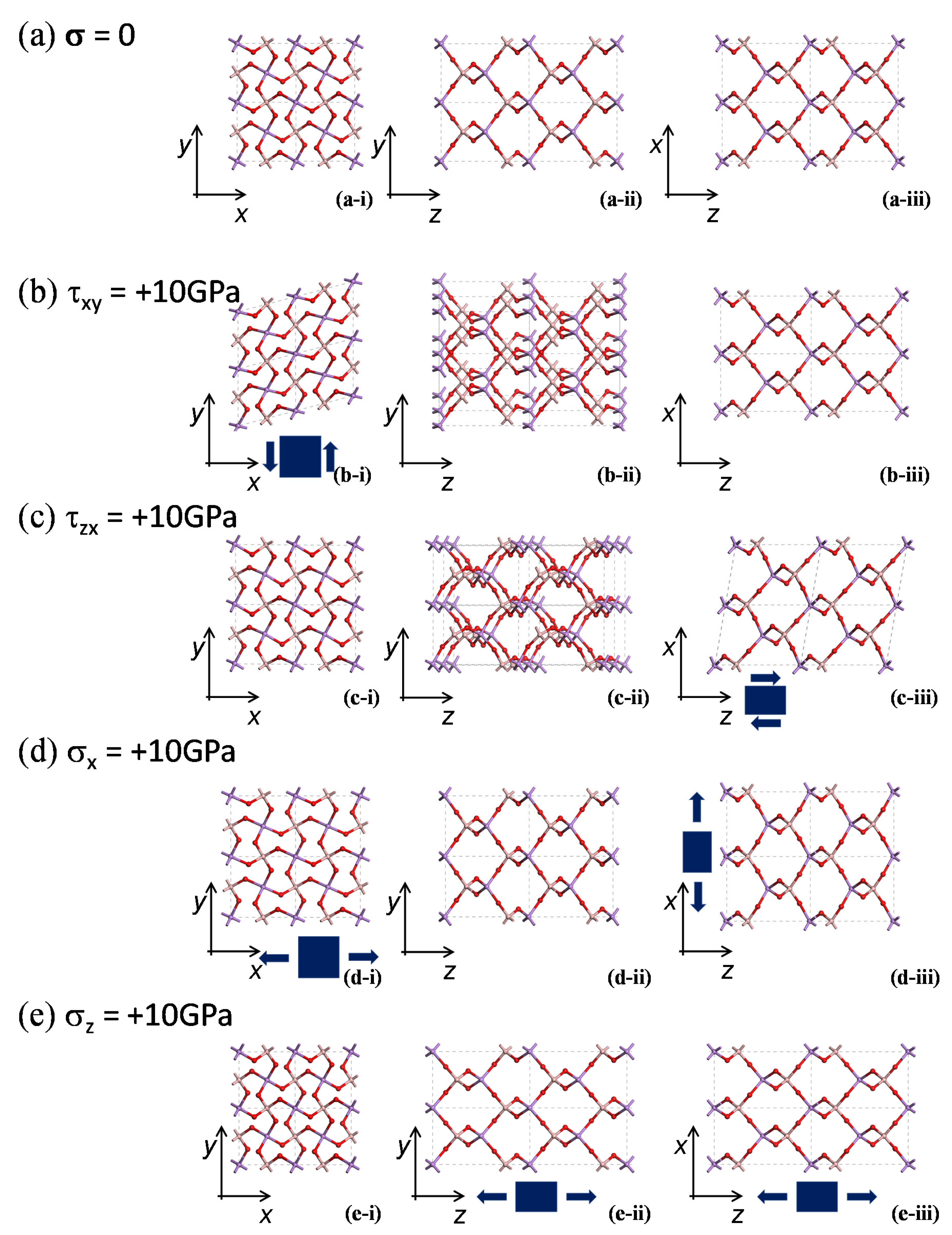
Images of the system when subjected to a shear load of +10GPa in the xy and xz planes are shown in Figure 4. To facilitate the discussion, these images of the sheared system, see Figure 4b,c, are shown alongside images of the equivalent unloaded system, see Figure 4a, and images of the system when subjected to uniaxial loads in the x and z direction, see Figure 4d,e. A quantification of the deformation is provided in the various plots shown in Figure 5, Figure 6, Figure 7, Figure 8 and Figure 9, where Figure 5 reports the cell parameters; Figure 6 reports the Lagrangian strains; Figure 7 reports deformations in terms of changes in bond lengths, bond angles and torsion angles; Figure 8 reports deformations in terms of changes in to the tetrahedral shapes; and Figure 9 reports deformations in terms of changes in terms of the 2D ‘connected squares’ motif as projected by the 3D tetrahedra in the xy-plane. In all cases, it should be noted that, due to symmetry, the behaviour in the xz and yz planes are equivalent to each other (only the behaviour in the xz plane is reported here). Similarly, uniaxial loading in the x has the same effect loading in the y direction and thus only the behaviour for uniaxial loading in the x-direction is presented here. From these results, it is evident that the systems are not resistant to shear and, the molecular level deformations, which will be discussed in more detail below, are comparable in magnitude to those arising from uniaxial loading.
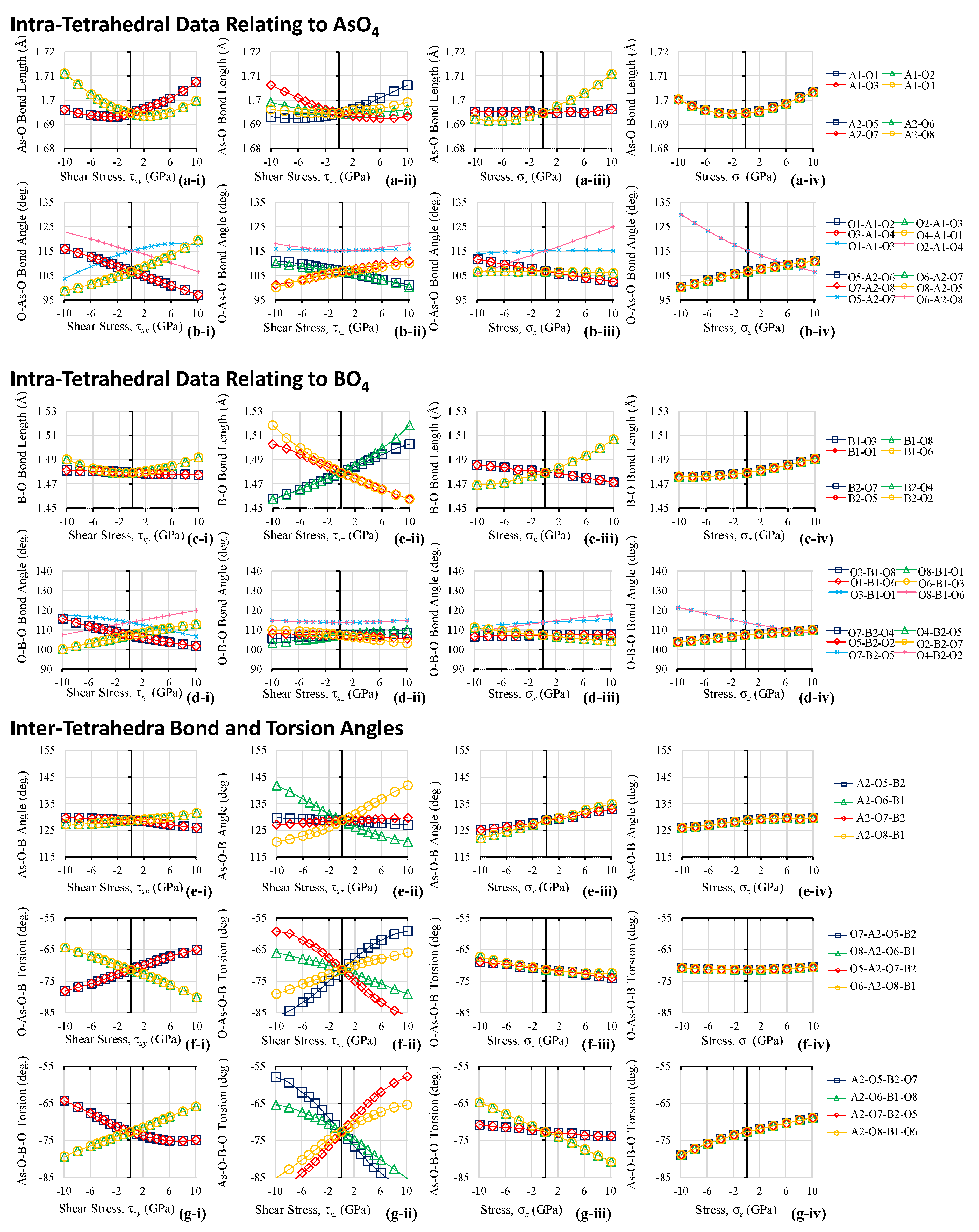
Before looking at the effect of the different loads, it is important to recall that BAsO4, like other crystalline systems, should not be considered as a purely mechanical system. What is remarkable, nonetheless, is that although the simulation protocol looks at the system through a rather complex quantum mechanical formulation, the interpretation of the results can still, to quite a reasonable approximation, be performed through a rather simple mechanical interpretation that looks at BAsO4 simply as a ‘mechanical structure’ obeying rather simple rules. General rules that seem to apply are that the deformations are predominantly due to changes in the angles, i.e., changes in angles between the tetrahedra (the B–O–As angles and in the O-B-O-As and O-As-O-B torsion angles) as well as changes in the O–M–O (M = B, As) within he tetrahedra themselves. Bond lengths also change, but to a lower extent where, in general, B-O bond lengths tend to change more than the As-O bonds. In fact, a general trend is that the smaller BO4 tetrahedra have more pronounced bond length changes whilst the larger AsO4 tetrahedra have more pronounced O–M–O angle changes. This difference in the manner of deformation of the BO4 and AsO4 tetrahedra can, at least in part, be due to actual differences in the size: from a purely mechanical perspective, the longer O–As bond is expected to be a more effective lever than the shorter O–B bond, thus facilitating changes in O–As–O angles compared to the O–B–O angles. From a chemistry perspective, it is also known that arsenic can form slightly more covalent and less polarised bonds with oxygen when compared to boron. Such a difference in the covalent character is due to the difference of the electronegativities of boron and arsenic (arsenic is slightly more electronegative than boron). In addition, the two atoms have a different oxidation state in this crystal structure (boron: 3+, arsenic: 5+) which contributes to make the BO4 tetrahedra being smaller than the AsO4 tetrahedra. All this results in slightly more “deformation resistant” O–As bonds when compared to O–B bonds, and a more deformable O–As–O bond angle as opposed to O–B–O.
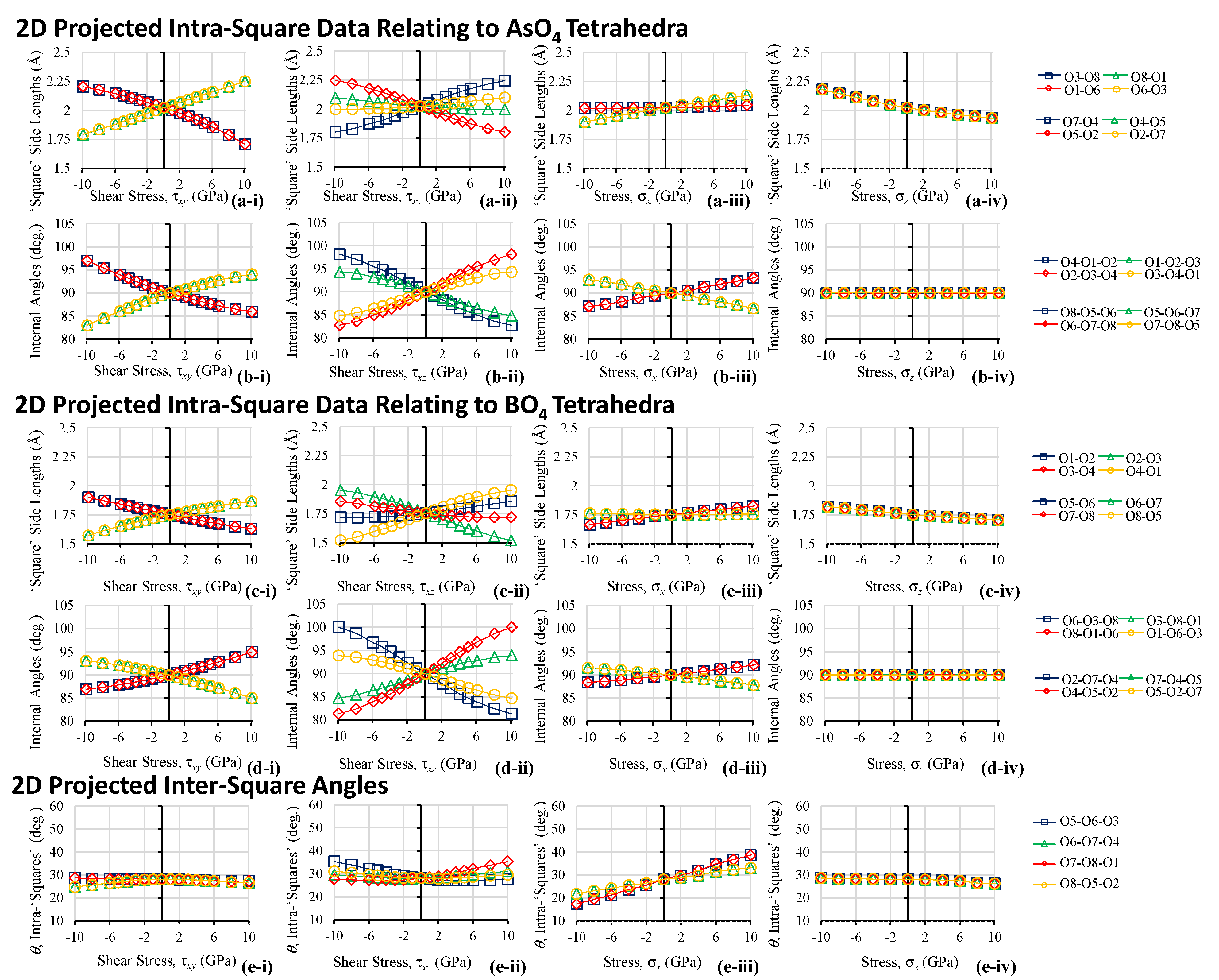
Looking in more detail at the shear deformations in the x–y plane and attempting to interpret these both in terms of the 2D projections in the (001) x–y plane, one may note that shear loading in the plane of the squares does not result any appreciable relative rotation of the squares. Instead, shear loading in the x-y plane results in extensive deformations of the squares themselves which tend to adopt a parallelogram-like shape of the Type IIα form [75]. Such a shape may be considered as a sheared variation of the Type II connected rectangles [76], a motif which is known to be present in the (100) and (010) planes of α-cristobalite [77,78]. All this is very clearly evident from images of the deformed system in Figure 4 and from Figure 9i which quantifies the deformation in terms of the 2D model, from a ‘rotating squares’ perspective and from the quantification in terms of percentages changes in length shown in Figure 10i. These deformations may be even more visible if one had to look at the deformed structures where the BO4 and AsO4 are depicted as actual tetrahedra (see Figure 11). From a quantitative perspective, we note that the change in the side lengths of the projected ‘squares’ is so excessive that these change by as much as 25% from τxy = −10 GPa to τxy = +10 GPa. The ‘squares’ that deform the most are those which relate to the AsO4 tetrahedra where the deformations and are caused primarily by changes in the O-M-O bond angles (which change by as much as c. 20° for a change from τxy = −10 GPa to τxy = +10 GPa) rather than the bond lengths, which change by less than 1%. Interestingly, the bond lengths do not follow a linear relation with applied shear stress and tend to increase in length for both a positive and a negative shear. In terms of angles, one may note that the 90° square angles also change in a non-insignificant manner when subjected to a shear, and much more than the angle between the ‘squares’ themselves, as evident to comparing Figure 9b-i and Figure 9d-i with Figure 9e-i. All this suggests that, from the perspective of the 2D projected squares, shear loading results primarily (and almost exclusively) in deformations of the ‘squares’ (which tend to become more like the ‘Type IIα parallelograms’ [75]) rather than their relative rotation. Thus, a comprehensive look at the deformations in the x-y plane suggests that while uniaxial loading in the [100] x-direction (and, by symmetry, uniaxial loading in the [010] y-direction) favours a ‘rotating squares’ mode of deformation leading to auxetic behaviour, shear loading in the xy-plane favours deformation of the squares themselves, a non-auxetic inducing mechanism. This finding is rather important as it explains both the anisotropy in the Poisson’s ratio and its deviation from the idealised value of −1 for rotating squares. Although the structural requirements are present (0 GPa system projects in the (001) plane as almost perfect squares, see Figure 1b, the mechanistic requirement to have perfectly rigid units which simply rotate relative to each other is not there. Such deviations from the ideal behaviour are to be expected, since the ‘squares’ in this system are mere 2D projections of 3D molecular tetrahedra which cannot be expected to behave as perfectly rigid units. In fact, if one had to look at the tetrahedra and how they deform when a shear load in the x-y plane is applied, see Figure 8i, one would notice that the four tetrahedra in the system are becoming quite irregular upon shearing, hence explaining the observation that their projection in the x-y plane no longer results in squares.
The magnitude of compliance term s66 (=Gxy−1) is rather high compared to the other sii signifying that the crystal is quite weak in shear in this plane. From an auxeticity perspective, this is rather unfortunate as the low-shear modulus indicates deviation from ideal behaviour for the maximisation of auxeticity. It is more than likely that, had the material been more resistant to shear deformation, the extent of auxeticity would have been more pronounced. This weakness in shear is also noticeable in the other (010) and (100) planes where, for example, we may note that the angle changes that occur on shearing in the x-z plane are some of the more pronounced angle changes for any form of loading. The same can be said for the bond length changes. In this case we note that, once again, there are non-negligible deformations of the tetrahedra, but this time, the most pronounced changes occur in the angles between the tetrahedra through changes in the B–O–As bond angles and the torsion angles. An interesting feature to note is that, although the shear load is being applied in the x–z plane, there are still some observable deformations in the x–y plane where, once again, the deformation projects primarily as deformations of ‘squares’ rather than their relative rotation. This once again emphasises the fact that the tetrahedra, or their 2D projections as ‘squares’, cannot be considered as rigid units. It is also interesting to note the rather large inter-tetrahedral bond angle changes do not project in the x-y plane as relative rotations of squares, which further emphasises the fact that this material should not be treated as a simple ‘unimode’ structure.
Before concluding it is important to note some of the strengths and limitations of this work. First and foremost, a strength of this work is that one would not have a comprehensive picture of how a material behaves under applied mechanical loads without looking at the behaviour of materials when these are sheared. The availably of such information and its analysis as presented here helps to complete this discussion on the properties of BAsO4. In this respect, it is rather unfortunate that shear behaviour is very often ignored in such studies, particularly given the wealth of information that can be derived from it. In this particular case, this work has identified an important mechanistic feature related to the ‘rotating squares’ description of BAsO4 in the auxetic (001) plane that would come in useful for formulation of analytical models of such materials. In fact, it has been shown that for a proper formulation of such a model, one would need to ensure that the ‘squares’ need to have the capability to become ‘Type IIα parallelograms’ [75] upon shearing. On the same note, this work provides further evidence that it is essential that any model for BAsO4 would need to incorporate the possibility of the tetrahedral/square units to deform rather than behave as simple ‘rotating rigid units’. A limitation of this work is that it was based entirely on results of simulations. In this case, this was mitigated through the use of a DFT methodology, rather than a force-field based approach as used in the past, which methods are known to be less prone to transferability errors.
5. Conclusions
This work has presented and discussed the behaviour of BAsO4 when subjected to shear loading thus enabling a better understanding of this material, which is now known be both auxetic and exhibiting NLC. From this work, further evidence was obtained that deformation of the BO4 and AsO4 tetrahedra, which project as ‘squares’ in the auxetic (001) plane, cannot be assumed to be negligible. In fact, it was now shown that such deformations become the most prominent mode of deformation upon shearing. It was further discussed that this can explain the particular values of Poisson’s ratio for this material, which are less than the −1 predicted for idealised models. All this provides highly valuable information should there be attempts to formulate analytical models for these types of materials.
Author Contributions
All authors were involved in the discussion. J.N.G.-C. conceived the work, performed the simulations, analysed the data and prepared the first draft. L.V.-Ż. supervised the work. J.N.G. and K.W.W. prepared the final version manuscript. All authors have read and agreed to the published version of the manuscript.
Funding
This work was financed by the Malta Council for Science & Technology through FUSION: The R&I Technology Development Programme 2018, grant No. R&I-2017-033-T and by grant No. 2017/27/B/ST3/02955 of the National Science Centre, Poland.
Acknowledgments
J.N.G.-C. and J.N.G. gratefully acknowledge the support of the project A-ROW, grant No. R&I-2017-033-T, financed by the Malta Council for Science & Technology through FUSION: The R&I Technology Development Programme 2018. K.W.W. gratefully acknowledges the support of grant No. 2017/27/B/ST3/02955 of the National Science Centre, Poland.
Conflicts of Interest
The authors declare no conflict of interest.
References
- Schulze, G.E.R. Die Kristallstruktur von BPO4 und BAsO4. Naturwissenschaften 1933, 21, 562. [Google Scholar] [CrossRef]
- Schulze, G. Die Kristallstruktur von BPO4 und BAsO4. Z. Phys. Chem. 1934, B24, 215–240. [Google Scholar] [CrossRef]
- Schulze, G. Boron Arsenate. J. Am. Chem. Soc. 1935, 57, 883. [Google Scholar] [CrossRef]
- Berger, E.M. Sur quelques Reactions Amorcees. C. R. Acad. Sci. 1920, 170, 1492. [Google Scholar]
- Gruner, E. Phosphat- und Arsenathydrate dreiwertiger Elemente, I. Borphosphat- und Borarsenathydrate. Z. Anorg. Allg. Chem. 1934, 219, 181–191. [Google Scholar] [CrossRef]
- Levi, G.R.; Ghiron, D. Chem. Zbl. 1934; 1, 1719.
- Schumb, W.C.; Hartford, W.H. Condensation Reactions of Boric Acid. J. Am. Chem. Soc. 1934, 56, 2613–2615. [Google Scholar] [CrossRef]
- Nieuwenkamp, W. Die Kristallstruktur des Tief-Cristobalits SiO2. Z. Kristallogr. Cryst. Mater. 1935, 92, 82–88. [Google Scholar] [CrossRef]
- Shafer, E.C.; Shafer, M.W.; Roy, R. Studies of Silica Structure Phases II: Data on FePO4, FeAsO4, MnPO4, BPO4, AlVO4 and others. Z. Kristallogr. 1956, 108, 263–275. [Google Scholar] [CrossRef]
- Baykal, A.; Evren, A. Hydrothermal and Microwave-Assisted Synthesis of Boroarsenate, BAsO4. Turk. J. Chem. 2006, 30, 723–730. [Google Scholar]
- Dagdelen, J.; Montoya, J.; de Jong, M.; Persson, K. Computational prediction of new auxetic materials. Nat. Commun. 2017, 8, 323. [Google Scholar] [CrossRef] [Green Version]
- Grima-Cornish, J.N.; Vella-Żarb, L.; Grima, J.N. Negative Linear Compressibility and Auxeticity in Boron Arsenate. Ann. Phys. 2020, 532, 1900550. [Google Scholar] [CrossRef]
- Haines, J.; Chateau, C.; Léger, J.M.; Bogicevic, C.; Hull, S.; Klug, D.D.; Tse, J.S. Collapsing Cristobalitelike Structures in Silica Analogues at High Pressure. Phys. Rev. Lett. 2003, 91, 015503. [Google Scholar] [CrossRef] [PubMed]
- Lakes, R.S. Negative-Poisson’s-Ratio Materials: Auxetic Solids. Annu. Rev. Mater. Res. 2017, 47. [Google Scholar] [CrossRef]
- Lim, T.-C. Auxetic Materials and Structures, 1st ed.; Springer: Cham, Switzerland, 2015; ISBN 978-981-287-274-6. [Google Scholar]
- Cairns, A.B.; Goodwin, A.L. Negative linear compressibility. Phys. Chem. Chem. Phys. 2015, 17, 20449–20465. [Google Scholar] [CrossRef] [PubMed] [Green Version]
- Gibson, L.J.; Ashby, M.F.; Schajer, G.S.; Robertson, C.I. The Mechanics of Two-Dimensional Cellular Materials. Proc. R. Soc. A Math. Phys. Eng. Sci. 1982, 382, 25–42. [Google Scholar]
- Gibson, L.J.; Ashby, M.F. Cellular Solids: Structure and Properties, 2nd ed.; Cambridge University Press: Cambridge, UK, 1997; ISBN 0521495601. [Google Scholar]
- Alderson, K.L.; Alderson, A.; Smart, G.; Simkins, V.R.; Davies, P.J. Auxetic polypropylene fibres:Part 1—Manufacture and characterisation. Plast. Rubber Compos. 2002, 31, 344–349. [Google Scholar] [CrossRef]
- He, C.; Liu, P.; Griffin, A.C. Toward Negative Poisson Ratio Polymers through Molecular Design. Macromolecules 1998, 31, 3145–3147. [Google Scholar] [CrossRef]
- Friis, E.A.; Lakes, R.S.; Park, J.B. Negative Poisson’s ratio polymeric and metallic foams. J. Mater. Sci. 1988, 23, 4406–4414. [Google Scholar] [CrossRef]
- Lakes, R.S. Deformation mechanisms in negative Poisson’s ratio materials: Structural aspects. J. Mater. Sci. 1991, 26, 2287–2292. [Google Scholar] [CrossRef]
- Scarpa, F.; Tomlin, P.J. On the transverse shear modulus of negative Poisson’s ratio honeycomb structures. Fatigue Fract. Eng. Mater. Struct. 2000, 23, 717–720. [Google Scholar] [CrossRef]
- Gatt, R.; Vella Wood, M.; Gatt, A.; Zarb, F.; Formosa, C.; Azzopardi, K.M.; Casha, A.; Agius, T.P.; Schembri-Wismayer, P.; Attard, L.; et al. Negative Poisson’s ratios in tendons: An unexpected mechanical response. Acta Biomater. 2015, 24, 201–208. [Google Scholar] [CrossRef]
- Novikova, N.E.; Lisovenko, D.S.; Sizova, N.L. Peculiarities of the Structure, Moduli of Elasticity, and Knoop Indentation Patterns of Deformation and Fracture of Single Crystals of Potassium, Rubidium, Cesium, and Ammonium Hydrophthalates. Crystallogr. Rep. 2018, 63, 438–450. [Google Scholar] [CrossRef]
- Alderson, A.; Evans, K.E. Molecular origin of auxetic behavior in tetrahedral framework silicates. Phys. Rev. Lett. 2002, 89, 225503. [Google Scholar] [CrossRef]
- Grima-Cornish, J.N.; Vella-Żarb, L.; Grima, J.N. On the behaviour of β-cristobalite-like BAsO4 when subjected to uniaxial loading in its [001] direction and the implications on its ‘negative’ characteristics. Phys. Status Solidi B 2020. [Google Scholar] [CrossRef]
- Evans, K.E.; Nkansah, M.A.; Hutcherson, I.J.; Rogers, S.C. Molecular network design. Nature 1991, 353, 124. [Google Scholar] [CrossRef]
- Evans, K.E.; Alderson, A. Auxetic Materials: Functional Materials and Structures from Lateral Thinking! Adv. Mater. 2000, 12, 617–628. [Google Scholar] [CrossRef]
- Wojciechowski, K.W. Two-Dimensional isotropic system with a negative poisson ratio. Phys. Lett. A 1989, 137, 60–64. [Google Scholar] [CrossRef]
- Wojciechowski, K.W.; Branka, A.C. Auxetics: Materials and Models with Negative Poisson’s Ratios. Mol. Phys. Rep. 1994, 6, 71–85. [Google Scholar]
- Baughman, R.H.; Galvão, D.S. Crystalline networks with unusual predicted mechanical and thermal properties. Nature 1993, 365, 735–737. [Google Scholar] [CrossRef]
- Grima-Cornish, J.N.; Grima, J.N.; Evans, K.E. On the Structural and Mechanical Properties of Poly(Phenylacetylene) Truss-Like Hexagonal Hierarchical Nanonetworks. Phys. Status Solidi B 2017, 254, 1700190. [Google Scholar] [CrossRef]
- Strek, T.; Maruszewski, B.T.; Narojczyk, J.W.; Wojciechowski, K.W. Finite Element Analysis of Auxetic Plate Deformation. J. Non Cryst. Solids 2008, 354, 4475–4480. [Google Scholar] [CrossRef]
- Grima-Cornish, J.N.; Grima, J.N.; Attard, D. Negative Mechanical Materials and Metamaterials: Giant Out-of-Plane Auxeticity from Multi-Dimensional Wine-Rack-like Motifs. MRS Adv. 2020, 5, 717–725. [Google Scholar] [CrossRef]
- Grima-Cornish, J.N.; Grima, J.N.; Attard, D. A Novel Mechanical Metamaterial Exhibiting Auxetic Behavior and Negative Compressibility. Materials 2019, 13, 79. [Google Scholar] [CrossRef] [PubMed] [Green Version]
- Grima, J.N.; Evans, K.E. Auxetic behavior from rotating squares. J. Mater. Sci. Lett. 2000, 19, 1563–1565. [Google Scholar] [CrossRef]
- Grima, J.N.; Mizzi, L.; Azzopardi, K.M.; Gatt, R. Auxetic Perforated Mechanical Metamaterials with Randomly Oriented Cuts. Adv. Mater. 2016, 28. [Google Scholar] [CrossRef] [PubMed]
- Grima, J.N.; Gatt, R. Perforated sheets exhibiting negative Poisson’s ratios. Adv. Eng. Mater. 2010, 12. [Google Scholar] [CrossRef]
- Milton, G.W. Complete characterization of the macroscopic deformations of periodic unimode metamaterials of rigid bars and pivots. J. Mech. Phys. Solids 2013, 61, 1543–1560. [Google Scholar] [CrossRef] [Green Version]
- Farrugia, P.S.; Gatt, R.; Grima, J.N. The push drill mechanism as a novel method to create 3D mechanical metamaterial structures. Phys. Status Solidi RRL 2020, 2000125. [Google Scholar] [CrossRef]
- Attard, D.; Farrugia, P.S.; Gatt, R.; Grima, J.N. Starchirals—A novel class of auxetic hierarchal structures. Int. J. Mech. Sci. 2020, 179. [Google Scholar] [CrossRef]
- Sigmund, O. Tailoring materials with prescribed elastic properties. Mech. Mater. 1995, 20, 351–368. [Google Scholar] [CrossRef]
- Wang, Z.; Hu, H. Auxetic materials and their potential applications in textiles. Text. Res. J. 2014. [Google Scholar] [CrossRef]
- Gatt, R.; Mizzi, L.; Azzopardi, J.I.; Azzopardi, K.M.; Attard, D.; Casha, A.; Briffa, J.; Grima, J.N. Hierarchical Auxetic Mechanical Metamaterials. Sci. Rep. 2015, 5, 8395. [Google Scholar] [CrossRef] [PubMed] [Green Version]
- Mizzi, L.; Mahdi, E.M.; Titov, K.; Gatt, R.; Attard, D.; Evans, K.E.; Grima, J.N.; Tan, J.C. Mechanical metamaterials with star-shaped pores exhibiting negative and zero Poisson’s ratio. Mater. Des. 2018, 146, 28–37. [Google Scholar] [CrossRef]
- Lim, T.-C. A class of shape-shifting composite metamaterial honeycomb structures with thermally-adaptive Poisson’s ratio signs. Compos. Struct. 2019, 226, 111256. [Google Scholar] [CrossRef]
- Dudek, K.K.; Wolak, W.; Dudek, M.R.; Caruana-Gauci, R.; Gatt, R.; Wojciechowski, K.W.; Grima, J.N. Programmable magnetic domain evolution in magnetic auxetic systems. Phys. Status Sol. RRL 2017, 11, 1700122. [Google Scholar] [CrossRef]
- Allen, T.; Duncan, O.; Foster, L.; Senior, T.; Zampieri, D.; Edeh, V.; Alderson, A. Auxetic foam for snow-sport safety devices. In Snow Sports Trauma and Safety: Conference Proceedings of the International Society for Skiing Safety; Springer: Cham, Switzerland, 2016. [Google Scholar]
- Alderson, A.; Davies, P.J.; Williams, M.R.; Evans, K.E.; Alderson, K.L.; Grima, J.N. Modelling of the mechanical and mass transport properties of auxetic molecular sieves: An idealised organic (polymeric honeycomb) host-guest system. Mol. Simul. 2005, 31, 897–905. [Google Scholar] [CrossRef]
- Alderson, A.; Alderson, K.L.; Evans, K.E.; Grima, J.N.; Williams, M.R.; Davies, P.J. Modelling the deformation mechanisms, structure-property relationships and applications of auxetic nanomaterials. Phys. Status Solidi B 2005, 242. [Google Scholar] [CrossRef]
- Ali, M.N.; Busfield, J.J.C.; Rehman, I.U. Auxetic oesophageal stents: Structure and mechanical properties. J. Mater. Sci. Mater. Med. 2014, 25, 527–553. [Google Scholar] [CrossRef]
- Gatt, R.; Caruana-Gauci, R.; Attard, D.; Casha, A.R.; Wolak, W.; Dudek, K.; Mizzi, L.; Grima, J.N. On the properties of real finite-sized planar and tubular stent-like auxetic structures. Phys. Status Solidi B 2014, 251. [Google Scholar] [CrossRef]
- Lim, T. 2D Structures Exhibiting Negative Area Compressibility. Phys. Status Solidi B 2017, 1–11. [Google Scholar] [CrossRef]
- Cairns, A.B.; Thompson, A.L.; Tucker, M.G.; Haines, J.; Goodwin, A.L. Rational Design of Materials with Extreme Negative Compressibility: Selective Soft-Mode Frustration in KMn[Ag(CN)2]3. J. Am. Chem. Soc. 2012, 134, 4454–4456. [Google Scholar] [CrossRef]
- Gatt, R.; Grima, J.N. Negative compressibility. Phys. Status Solidi RRL 2008, 2, 236–238. [Google Scholar] [CrossRef]
- Grima, J.N.; Attard, D.; Gatt, R. Truss-Type systems exhibiting negative compressibility. Phys. Status Solidi B 2008, 245, 2405–2414. [Google Scholar] [CrossRef]
- Degabriele, E.P.; Attard, D.; Grima-Cornish, J.N.; Caruana-Gauci, R.; Gatt, R.; Evans, K.E.; Grima, J.N. On the Compressibility Properties of the Wine-Rack-Like Carbon Allotropes and Related Poly(phenylacetylene) Systems. Phys. Status Solidi B 2019, 256, 1800572. [Google Scholar] [CrossRef] [Green Version]
- Baughman, R.H.; Stafström, S.; Cui, C.; Dantas, S.O. Materials with negative compressibilities in one or more dimensions. Science 1998, 279, 1522–1524. [Google Scholar] [CrossRef] [PubMed]
- Qu, J.; Kadic, M.; Wegener, M. Poroelastic metamaterials with negative effective static compressibility. Appl. Phys. Lett. 2017, 110, 171901. [Google Scholar] [CrossRef]
- Lakes, R.; Wojciechowski, K.W. Negative compressibility, negative Poisson’s ratio, and stability. Phys. Status Solidi B 2008, 245, 545–551. [Google Scholar] [CrossRef]
- Goldstein, R.V.; Gorodtsov, V.A.; Lisovenko, D.S. Auxetic mechanics of crystalline materials. Mech. Solids 2010, 45. [Google Scholar] [CrossRef]
- Baughman, R.H.; Shacklette, J.M.; Zakhidov, A.A.; Stafströ, S. Negative Poisson’s ratios as a common feature of cubic metals. Nature 1998, 392, 362–365. [Google Scholar] [CrossRef]
- Branka, A.C.; Heyes, D.M.; Wojciechowski, K.W. Auxeticity of cubic materials under pressure. Phys. Status Solidi B 2011, 248, 96–104. [Google Scholar] [CrossRef]
- Goldstein, R.V.; Gorodtsov, V.A.; Lisovenko, D.S.; Volkov, M.A. Negative Poisson’s ratio for cubic crystals and nano/microtubes. Phys. Mesomech. 2014, 17, 97–115. [Google Scholar] [CrossRef]
- Gorodtsov, V.A.; Lisovenko, D.S. Auxetics among Materials with Cubic Anisotropy. Mech. Solids 2020, 55, 461–474. [Google Scholar] [CrossRef]
- Goldstein, R.V.; Gorodtsov, V.A.; Lisovenko, D.S.; Volkov, M.A. Auxetics among 6-constant tetragonal crystals. Lett. Mater. 2015, 5, 409–413. [Google Scholar] [CrossRef] [Green Version]
- Goldstein, R.V.; Gorodtsov, V.A.; Lisovenko, D.S. Young’s modulus and Poisson’s ratio for seven-constant tetragonal crystals and nano/microtubes. Phys. Mesomech. 2015, 18, 213–222. [Google Scholar] [CrossRef]
- Nye, J.F. Physical Properties of Crystals: Their Representations by Tensors and Matrices; Clarendon Press: Wotton-Under-Edge, UK, 1957; ISBN 0198511655. [Google Scholar]
- Clark, S.J.; Segall, M.D.; Pickard, C.J.; Hasnip, P.J.; Probert, M.I.J.; Refson, K.; Payne, M.C. First principles methods using CASTEP. Z. Kristallogr. 2005, 220, 567–570. [Google Scholar] [CrossRef] [Green Version]
- Mason, W.P. Piezoelectric Crystals and Their Application to Ultrasonics; Van Nostrand: New York, NY, USA, 1950. [Google Scholar]
- Schlenker, J.L.; Gibbs, G.V.; Boisen Jnr, M.B. Strain-tensor components expressed in terms of lattice parameters. Acta Crystallogr. Sect. A 1978, 34, 52–54. [Google Scholar] [CrossRef]
- Becke, A.D. Density-functional exchange-energy approximation with correct asymptotic behavior. Phys. Rev. A 1988, 38, 3098–3100. [Google Scholar] [CrossRef]
- Perdew, J.P.; Burke, K.; Ernzerhof, M. Generalized gradient approximation made simple. Phys. Rev. Lett. 1996, 77, 3865–3868. [Google Scholar] [CrossRef] [PubMed] [Green Version]
- Grima, J.N.; Farrugia, P.S.; Gatt, R.; Attard, D. On the auxetic properties of rotating rhombi and parallelograms: A preliminary investigation. Phys. Status Solidi B 2008, 245. [Google Scholar] [CrossRef]
- Grima, J.N.; Gatt, R.; Alderson, A.; Evans, K.E. On the auxetic properties of “rotating rectangles” with different connectivity. J. Phys. Soc. Jpn. 2005, 74, 2866–2867. [Google Scholar] [CrossRef]
- Grima, J.N.; Gatt, R.; Alderson, A.; Evans, K.E. On the origin of auxetic behaviour in the silicate α-cristobalite. J. Mater. Chem. 2005, 15, 4003. [Google Scholar] [CrossRef]
- Grima, J.N.; Gatt, R.; Alderson, A.; Evans, K.E. An alternative explanation for the negative Poisson’s ratios in α-cristobalite. Mater. Sci. Eng. A 2006, 423, 219–224. [Google Scholar] [CrossRef]
Figure 1.
(a) The crystal structure of BAsO4 shown in (a-i) the (001) plane, (a-ii) the (100) and (a-iii) the (010) plane where the atoms are represented by spheres and the bonds by rods. The alignment shown here is in accordance with the IRE convention and is the one used in present work. (b) The representation of BAsO4 in terms of tetrahedra as projected in the (001) plane, which representation emphasises the ‘rotating squares’ motif. (c) The Poisson’s ratio in the (001) plane for loading in the plane, calculated using standard axis transformation technique. Note that the Poisson’s ratio is always negative in this plane where 0° corresponds to νxy = −0.33 (loading in the x-direction, defined by νxy = −εlateral/εaxial = −εy/εx = −s21/s11) whilst 90° corresponds to νyx (loading in the y-direction, defined by −εx/εy = −s12/s22).

Figure 2.
The atom labelling system used in this work were the two independent boron atoms, located at the centre of the faces being labels as B1 and B2, the arsenic atoms, located at the corners and the centre of the unit cell labelled A1 and A2 with the eight oxygen atoms labelled as O1–O8.
Figure 2.
The atom labelling system used in this work were the two independent boron atoms, located at the centre of the faces being labels as B1 and B2, the arsenic atoms, located at the corners and the centre of the unit cell labelled A1 and A2 with the eight oxygen atoms labelled as O1–O8.

Figure 3.
The manner how distances and angles were computed.

Figure 4.
(a) BAsO4 without applied loads, compared to BASO4 as this is subjected to (b) a shear stress of 10 GPa in the xy-plane, corresponding to the (001) plane and (c) a shear stress of 10 GPa in the xz-plane, corresponding to the (010) plane. Additionally, shown for comparison are the equivalent systems for (d) uniaxial loading in the x direction by +10 GPa, corresponding to the [100] direction, and (e) uniaxial loading in the z direction by +10 GPa, corresponding to the [001] direction. Panels (i), (ii) and (iii) show the xy, yx and xz planes, respectively.

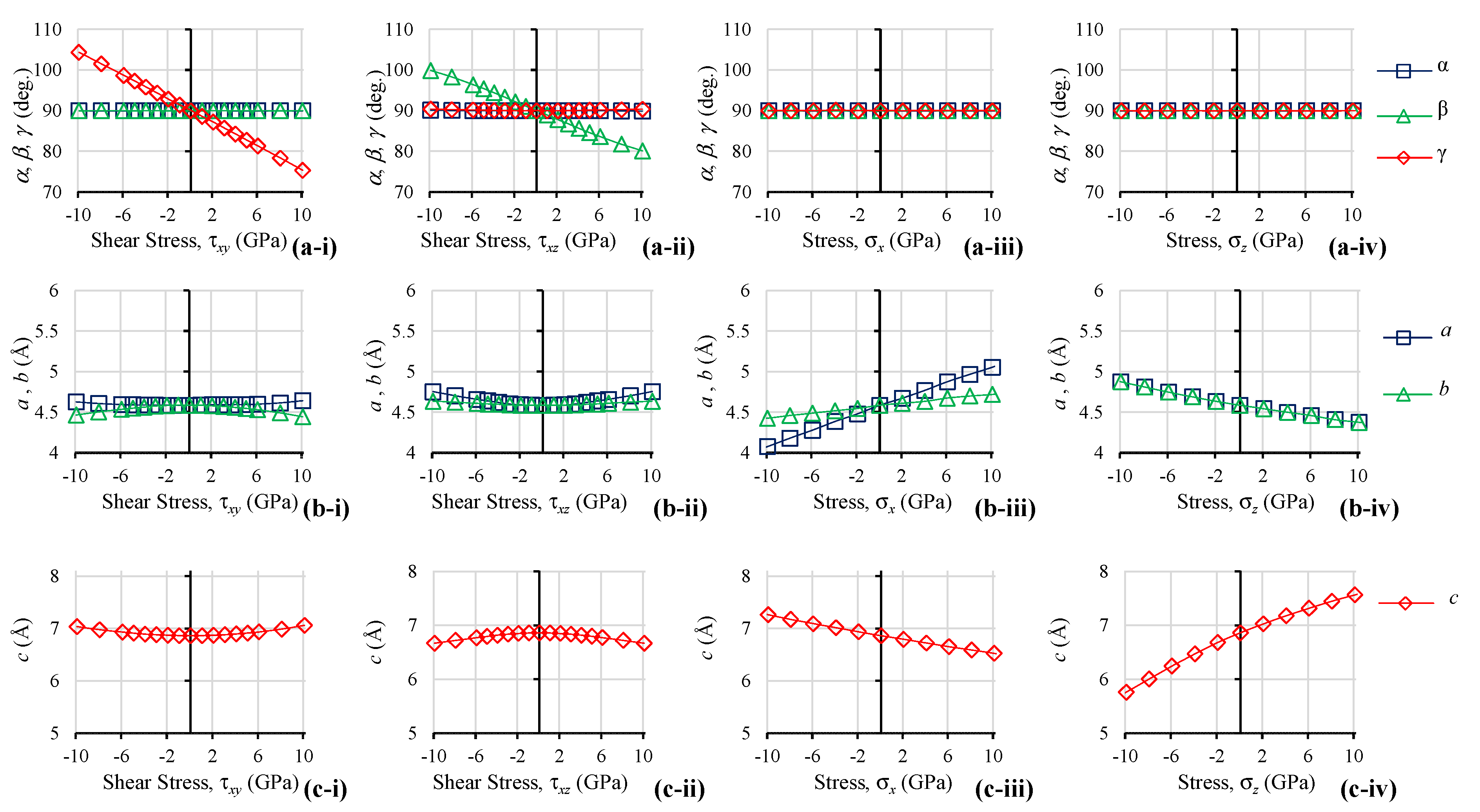
Figure 5.
The unit cell parameters as BAsO4 is subjected to (i) shear stresses in the xy-plane, corresponding to the (001) plane and (ii) shear stresses in the xz-plane, corresponding to the (010) plane. Additionally, shown for comparison is the equivalent data for (iii) uniaxial loading in the x direction, corresponding to the [100] direction, and (iv) uniaxial loading in the z direction, corresponding to the [001] direction where (a) shows the unit cell angles and (b,c) show the unit cell lengths.

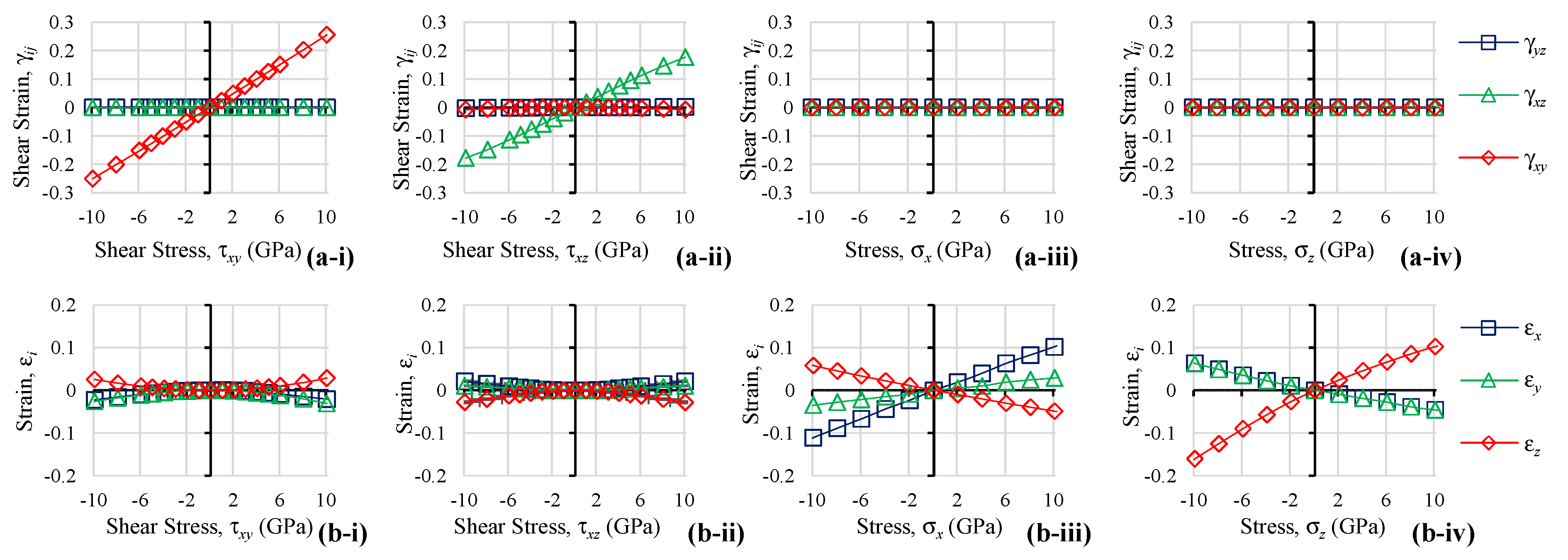
Figure 6.
The Lagrangian strains as BAsO4 is subjected to (i) shear stresses in the xy-plane, corresponding to the (001) plane and (ii) shear stresses in the xz-plane, corresponding to the (010) plane. Additionally, shown for comparison is the equivalent data for (iii) uniaxial loading in the x direction, corresponding to the [100] direction, and (iv) uniaxial loading in the z direction, corresponding to the [001] direction where (a) shows the shear strains and (b) shows the axial strains.

Figure 7.
Various measurements of (a,c) bond lengths, (b,d,e) bond angles and (f,g) torsion angles as BAsO4 is subjected to (i) shear stresses in the xy-plane, corresponding to the (001) plane and (ii) shear stresses in the xz-plane, corresponding to the (010) plane. Additionally, shown for comparison is the equivalent data for (iii) uniaxial loading in the x direction, corresponding to the [100] direction, and (iv) uniaxial loading in the z direction, corresponding to the [001] direction.

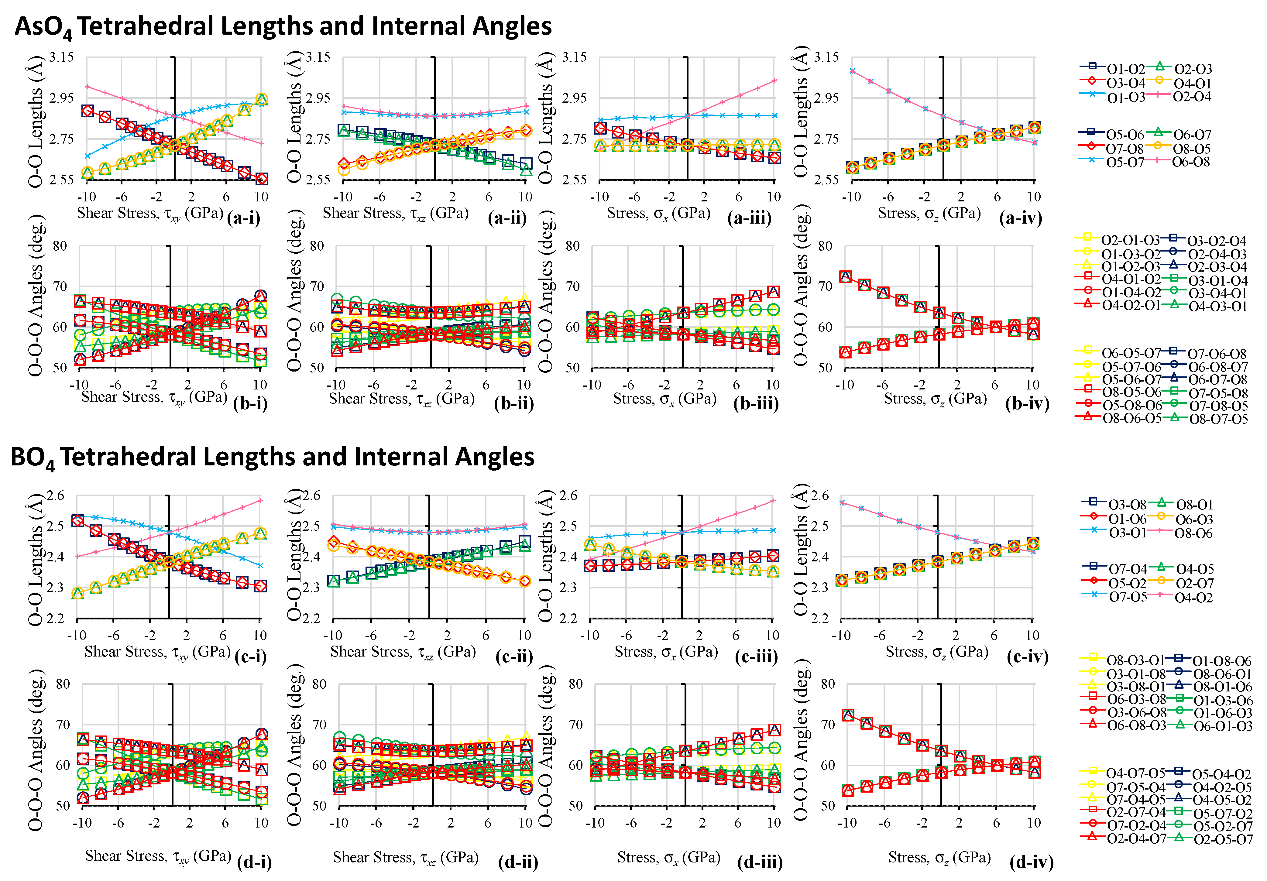
Figure 8.
Various measurements of (a,c) tetrahedral side lengths and (b,d) tetrahedral bond angles as BAsO4 is subjected to (i) shear stresses in the xy-plane, corresponding to the (001) plane and (ii) shear stresses in the xz-plane, corresponding to the (010) plane. Additionally, shown for comparison is the equivalent data for (iii) uniaxial loading in the x direction, corresponding to the [100] direction, and (iv) uniaxial loading in the z direction, corresponding to the [001] direction.

Figure 9.
Various measurements which describe the deformations in terms of changes in terms of the 2D ‘connected squares’ motif as projected by the 3D tetrahedra in the xy-plane where (a,c) report the side-length of the ‘squares’, (b,d) report the internal angles of the ‘squares’ and (e) reports the inter-‘square’ angles as BAsO4 is subjected to (i) shear stresses in the xy-plane, corresponding to the (001) plane and (ii) shear stresses in the xz-plane, corresponding to the (010) plane. Additionally, shown for comparison is the equivalent data for (iii) uniaxial loading in the x direction, corresponding to the [100] direction, and (iv) uniaxial loading in the z direction, corresponding to the [001] direction.

Figure 10.
Percentage changes of various length measurements. (a) Bond Lengths; (b) Tetrahedral Side Lengths; (c) 2D Projected ‘Square’ Lengths; (d) Cell Parameters.
Figure 10.
Percentage changes of various length measurements. (a) Bond Lengths; (b) Tetrahedral Side Lengths; (c) 2D Projected ‘Square’ Lengths; (d) Cell Parameters.

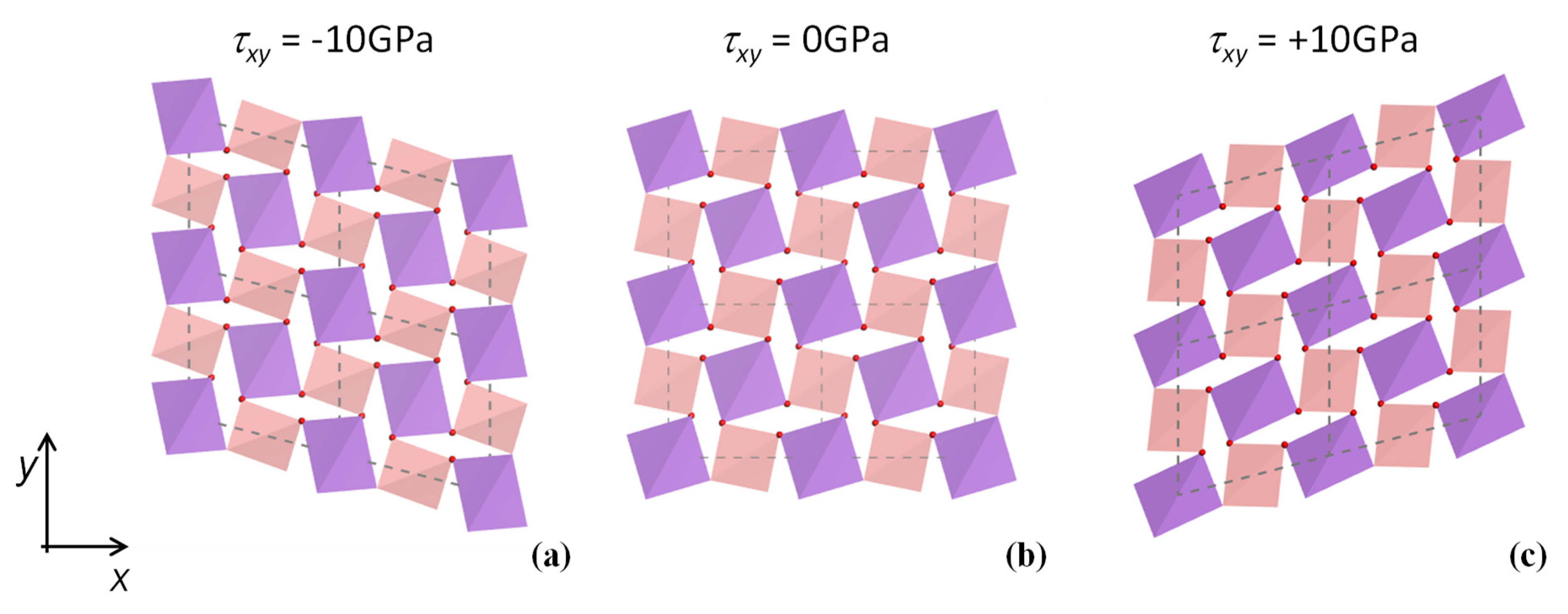
Figure 11.
The effect of shear loading in the (001) plane of BAsO4 where the BO4 and AsO4 units are represented as tetrahedra so as to illustrate better the deformation under shear where (a) shows the system being subjected to a -ve shear stress and (c) shows the system under a +ve shear stress. The system in (b) is unloaded.


Table 1.
The elements of the compliance matrix of BAsO4 as reported by Grima-Cornish et al. (2020) [12], which correspond to shear modulus Gxy = s66−1 = 40.5GPa. Note that these elements fulfil symmetry requirements for a tetragonal crystal [69]. After the application of standard axis transformations [69], the elements of this matrix may be used to compute the mechanical properties of the crystal in any direction/plane.
| sij (x10−12 Pa−1) | j = 1 | 2 | 3 | 4 | 5 | 6 |
| i = 1 | 10.4 | 3.4 | −5.1 | 0.0 | 0.0 | 0.3 |
| 2 | 3.4 | 10.4 | −5.1 | 0.0 | 0.0 | −0.3 |
| 3 | −5.1 | −5.1 | 12.6 | 0.0 | 0.0 | 0.0 |
| 4 | 0.0 | 0.0 | 0.0 | 18.9 | 0.0 | 0.0 |
| 5 | 0.0 | 0.0 | 0.0 | 0.0 | 18.9 | 0.0 |
| 6 | 0.3 | −0.3 | 0.0 | 0.0 | 0.0 | 24.7 |
Table 2.
(a) Boron arsenate as reported by Schulze [2]. (b) Relationship between the original fractional coordinates with symmetry applied and the fractional coordinates of the P1 system, together with the unique labelling system used to identify each atom within the unit cell.
Table 2.
(a) Boron arsenate as reported by Schulze [2]. (b) Relationship between the original fractional coordinates with symmetry applied and the fractional coordinates of the P1 system, together with the unique labelling system used to identify each atom within the unit cell.
| (a) The crystal structure of boron arsenate as reported by Schulze. | ||||||||||
| Unit Cell Properties | ||||||||||
| Space Group | ||||||||||
| a = b | 4.4580 | |||||||||
| c | 6.7960 | |||||||||
| 90° | ||||||||||
| Fractional Atomic Coordinates | ||||||||||
| B | 0.00000 | 0.50000 | 0.25000 | |||||||
| As | 0.00000 | 0.00000 | 0.00000 | |||||||
| O | 0.16000 | 0.26000 | 0.14000 | |||||||
| (b) The atom labelling system used in this work, see Figure 2. | ||||||||||
| Element | Fract. Coordinates | Transformation Applied | P1 Fract. Coordinates | Label | ||||||
| As | 0 | 0 | 0 | x | y | z | 0 | 0 | 0 | A1 |
| −x | −y | z | 0 | 0 | 0 | |||||
| y | −x | −z | 0 | 0 | 0 | |||||
| −y | x | −z | 0 | 0 | 0 | |||||
| x + ½ | y + ½ | z + ½ | 0.5 | 0.5 | 0.5 | A2 | ||||
| −x + ½ | −y + ½ | −z + ½ | 0.5 | 0.5 | 0.5 | |||||
| y + ½ | −x + ½ | −z + ½ | 0.5 | 0.5 | 0.5 | |||||
| −y + ½ | x + ½ | −z + ½ | 0.5 | 0.5 | 0.5 | |||||
| B | 0 | 0.5 | 0.25 | x | y | z | 0 | 0.5 | 0.25 | B1 |
| −x | −y | z | 0 | 0.5 | 0.25 | |||||
| y | −x | −z | 0.5 | 0 | 0.75 | B2 | ||||
| −y | x | −z | 0.5 | 0 | 0.75 | |||||
| x + ½ | y + ½ | z + ½ | 0.5 | 0 | 0.75 | |||||
| −x + ½ | −y + ½ | −z + ½ | 0.5 | 0 | 0.75 | |||||
| y + ½ | −x + ½ | −z + ½ | 0.5 | 0 | 0.75 | |||||
| −y + ½ | x + ½ | −z + ½ | 0.5 | 0 | 0.75 | |||||
| O | 0.16 | 0.26 | 0.14 | x | y | z | 0.16 | 0.26 | 0.14 | O1 |
| −x | −y | z | 0.84 | 0.74 | 0.14 | O3 | ||||
| y | -x | −z | 0.26 | 0.84 | 0.86 | O2 | ||||
| −y | x | −z | 0.74 | 0.16 | 0.86 | O4 | ||||
| x + ½ | y + ½ | z + ½ | 0.66 | 0.76 | 0.64 | O5 | ||||
| −x + ½ | −y + ½ | −z + ½ | 0.34 | 0.24 | 0.64 | O7 | ||||
| y + ½ | −x + ½ | −z + ½ | 0.76 | 0.34 | 0.36 | O6 | ||||
| −y + ½ | x + ½ | −z + ½ | 0.24 | 0.66 | 0.36 | O8 | ||||
Publisher’s Note: MDPI stays neutral with regard to jurisdictional claims in published maps and institutional affiliations. |
© 2021 by the authors. Licensee MDPI, Basel, Switzerland. This article is an open access article distributed under the terms and conditions of the Creative Commons Attribution (CC BY) license (https://creativecommons.org/licenses/by/4.0/).
Share and Cite
MDPI and ACS Style
Grima-Cornish, J.N.; Vella-Żarb, L.; Wojciechowski, K.W.; Grima, J.N. Shearing Deformations of β-Cristobalite-Like Boron Arsenate. Symmetry 2021, 13, 977. https://doi.org/10.3390/sym13060977
AMA Style
Grima-Cornish JN, Vella-Żarb L, Wojciechowski KW, Grima JN. Shearing Deformations of β-Cristobalite-Like Boron Arsenate. Symmetry. 2021; 13(6):977. https://doi.org/10.3390/sym13060977
Chicago/Turabian StyleGrima-Cornish, James N., Liana Vella-Żarb, Krzysztof W. Wojciechowski, and Joseph N. Grima. 2021. "Shearing Deformations of β-Cristobalite-Like Boron Arsenate" Symmetry 13, no. 6: 977. https://doi.org/10.3390/sym13060977
Note that from the first issue of 2016, this journal uses article numbers instead of page numbers. See further details here.